Intec ColorCut FB550 Series User manual

Intec Printing Solutions - Manual for ColorCut flat bed series FB550 ....................................................................................... Page No: 1
Dual Tool, Flatbed Digital Die-Cutters
ColorCut FB550 Series
Installation & Setup Guide - English
Revision: 2.0 0121

Intec Printing Solutions - Manual for ColorCut flat bed series FB550 ....................................................................................... Page No: 2

Intec Printing Solutions - Manual for ColorCut flat bed series FB550 ....................................................................................... Page No: 3
Contents
Chapter 1 -The Intec ColorCut FB550 Flatbed Series .................................. 5
1.1 INTRODUCTION ..................................................................................................7
1.2 SPECIFICATIONS ................................................................................................8
1.3 UNPACKING Contents of the ColorCut (Overview) ............................................. 9
1.4 UNPACKING Contents of ColorCut Flatbed (Detailed) ......................................10
1.5 IDENTIFYING KEY FEATURES of your ColorCut Flatbed .................................11
1.6 THE CONTROL PANEL (Overview of Navigation) ..............................................12
Chapter 2 - TOOLS for the Intec ColorCut Flatbed .................................... 14
2.1 CUTTER BLADES (An overview of Blade types) ...............................................15
2.2 THE BLADE HOLDER - an introduction ............................................................16
2.3 Replacing the blade ........................................................................................... 16
2.4 BLADE LENGTH - (Adjustment) .........................................................................17
Chapter 3 - INSTALLATION of your ColorCut Flatbed ............................... 18
3.0.1 OVERVIEW of installation steps ......................................................................19
3.1 Assembling the Stand, Cutter and Vacuum Pump ............................................20
Component parts of the stand .......................................................................20
Component parts of the vacuum fan pump ...................................................20
Assembly of stand ..........................................................................................21
Assembly of vacuum fan/pump ......................................................................21
3.2 Software Installation - Intec ColorCut Pro ......................................................... 22
ColorCut Pro Overview ................................................................................... 22
ColorCut Pro Installation.................................................................................22
3.3.1 Connecting and powering on the cutter. ........................................................25
Turning the cutter on (The Initialisation Process) ............................................25
3.3.2 Connecting to your computer ................................................................26
3.3.3 CONFIGURING COLORCUT PRO TO MATCH YOUR CUTTER ...........26
3.3.4 Customising the ColorCut Pro skin to your FB550 cutter ....................27
3.3.5 Output device ........................................................................................28
3.4 Installing Tools in your ColorCut ........................................................................ 29
3.5. Calibration of the FB550 Cutter ........................................................................30
3.5.1 Calibration of the Creasing Tool to the Cutting Tool ..............................30
3.5.2 Calibration of the Sensor Offset to the Cutting Blade ...........................34
3.6 Performing a test cut .........................................................................................37
3.5.1 Calibration of the Creasing Tool to the Cutting Tool ..............................37

Intec Printing Solutions - Manual for ColorCut flat bed series FB550 ....................................................................................... Page No: 4

Intec Printing Solutions - Manual for ColorCut flat bed series FB550 ....................................................................................... Page No: 5
1.1 Introduction
1.2 Specification
1.3 Unpacking overview
1.4 Identifying key features of your ColorCut Flatbed
1.5 Overview of the Control Panel
Chapter 1
Chapter 1 -The Intec ColorCut FB550 Flatbed Series

Intec Printing Solutions - Manual for ColorCut flat bed series FB550 ....................................................................................... Page No: 6

Intec Printing Solutions - Manual for ColorCut flat bed series FB550 ....................................................................................... Page No: 7
1.1 INTRODUCTION
INTEC COLORCUT FLATBED - DIGITAL CUTTING SOLUTION
The Intec ColorCut FB550 flatbed cutters are designed primarily to cut card and packaging
materials effectively. It is also used for cutting, vinyl, thin film, adhesive labels and magnetic
media.
There are also additional functions for die cutting sheet material, using perforated and
dashed cut features and the use of additional tools such as creasing which enables folding
on suitable card materials without the fib es on the boar d breaking when the material is
folded.
The ColorCut solution consists of 2 parts:
Hardware
An Intec Digital Cutting Engine
An Integrated Optical Sensor for automatic registration mark sensing
A Stand
A Vacuum Pump to provide suction for vacuum table.
An Optional Silencer/Acoustic Muffler to educe vacuum pump sound levels
A Vacuum connection hose
and
Software
The ColorCut Pr o cutter contr ol software contains two parts, (i) a pr ofessional
direct plug-in for Illustrator or CorelDRAW enabling you to assign cut lines or paths
created from Adobe Illustrator or CorelDRAW. (ii) a Production Studio application
that cuts your projects (either from within your graphics packge or as a seperate
application where jobs can be cut later using a job number or barcode).
Jobs can be cut without r egistration marks, however for accurate cutting your
files must contain four reference marks, known as SMAR Tmarks (described later
in the ColorCut Pr o Software manual) which can be automatically applied within
tthe ColorCut plug-in.
The optical sensor integrated into your ColorCut hardware detects the SMARTmark
in a fraction of a second and adapts the cut path to any variations in the origin,
scale or skew distortion of the print.
The software runs with the operating systems Windows 7, 8, 10.
Please use this guide to set up your Hardware and refer to the Software / ColorCut manual
to assist you in final calibration of the softwa e to the cutter including guidance on how to
use ColoCut Pro when designing and cutting your files

Intec Printing Solutions - Manual for ColorCut flat bed series FB550 ....................................................................................... Page No: 8
1.2 SPECIFICATIONS
INTEC COLORCUT FLATBED - SPECIFICATIONS
The Intec ColorCut FB550/FB750 and FB1150 series of flatbed cutters vary
primarily by the size of the cutting area.
Model Maximum Media
Area
Effective Contour
Cutting Area Stand
ColorCut FB550 350 x 520mm 330 x 488mm Yes
ColorCut FB750 475 x 670mm 456 x 640mm Yes
ColorCut FB1150 780 x 1080mm 740 x 1040mm Yes
In addition to the primary difference in workspace area and the cutting area. The
Intec ColorCut FB520/FB600/FB700/FB900 and FB1060 flatbed cutters have
different vacuum control systems to provide media hold-down during cutting.
Model Air Pump Vacuum
Power Vacuum Control Accoustic
Silencer
ColorCut FB550 400W 400W Fixed Optional
ColorCut FB750 750W 750W Fixed Yes
ColorCut FB1150 1000W 1000W Fixed Yes
Each cutter is supplied with 2 dif ferent cutting mats that ar e positioned on the
cutting table; the green self healing mat is typically used for kiss-cut applications
such as labels/decals or vinyl’ s. The Gr ey felt mat is actually the pr emium mat
and is also known as the superior cutting underlay . This is used for cut-thr ough
applications and any application using the creasing tool, as the mat enables some
‘give’ therefore providing a better crease. In addition, the grey superior cutting mat
can extend the life of your cutting blade for cut-through applications.
Intec Printing Solutions - Manual for ColorCut flat bed series FB550 ....................................................................................... Page No: 9
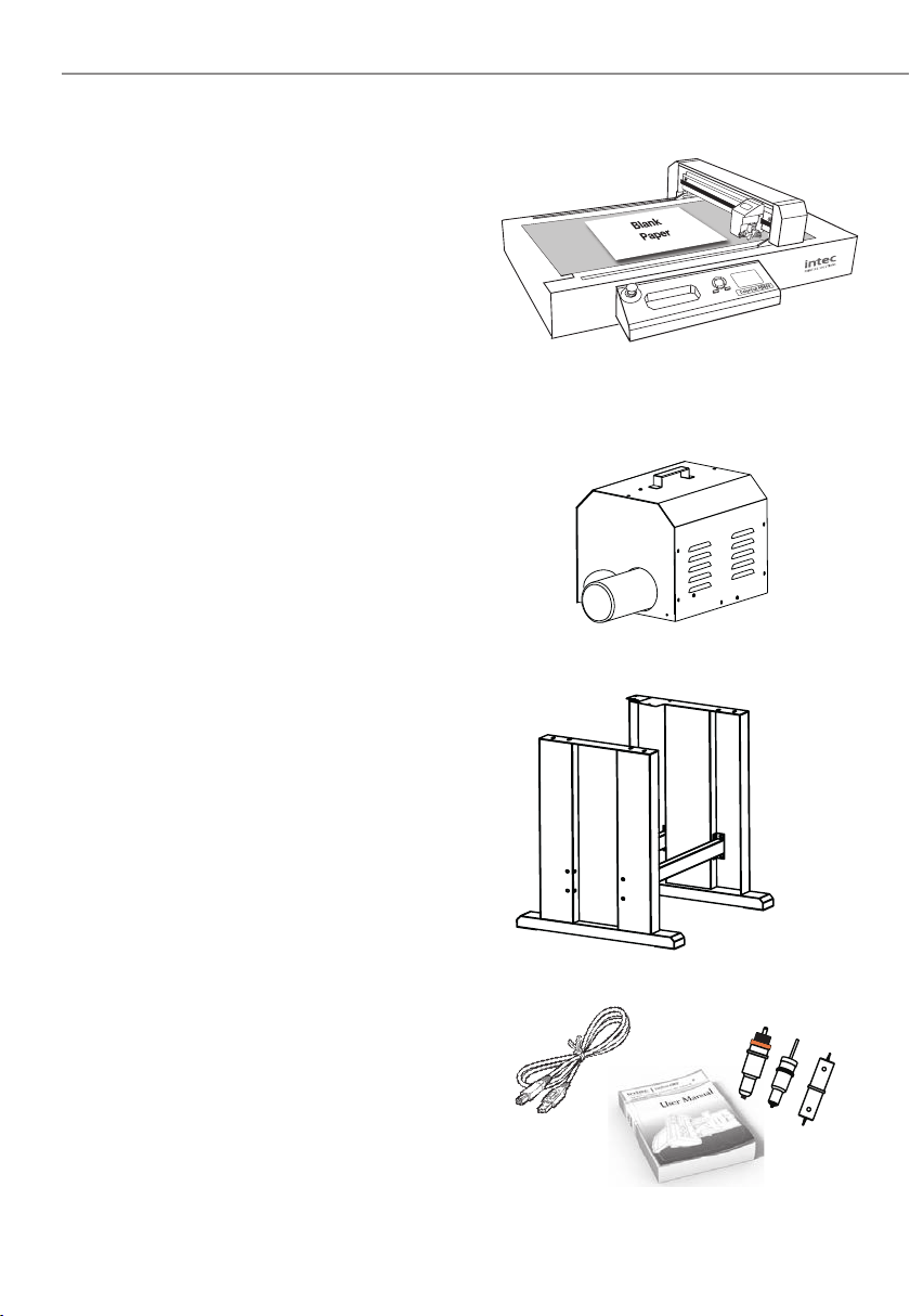
1.3 UNPACKING Contents of the ColorCut (Overview)
Your Intec ColorCut is packed in 1 crate.
The box contains :
The Intec ColorCut Cutting Engine. (Item (i))
The ColorCut Vacuum Pump (ii)
The Vacuum Pump Connector Hose (iii)
The Accessories box (iv)
And the ColorCut Stand (v)
The ColorCut Vacuum Pump and V acuum
Hose provide the vacuum to hold down
your media on the cutting table.
The stand pr ovides a perfect er gonomic
working height for your cutter.
The final items found inside the accessories
box include the power cable and USB cable
plus a disk containing your ColorCut Pr o
Software and license code. A Blade Holder,
a selection of Cutting Blades, a Calibration
Pen Tool and a Creasing Tool.
Item (i) - Intec ColorCut Cutting Engine
Item (ii) - ColorCut Vacuum Pump
(and Acoustic Silencer - Optional on FB550)
Item (iii) - Intec ColorCut Stand (FB550, FB750, FB1150)
Item (iv) - Manuals, USB & Power Cables
*Optional on FB550

Intec Printing Solutions - Manual for ColorCut flat bed series FB550 ..................................................................................... Page No: 10
1.4 UNPACKING Contents of ColorCut Flatbed (Detailed)
Item Qty Description / Purpose
Intec Flatbed Cutter 1 Main Cutting Engine
Vacuum Air Pump 1 Air fan that provides Vacuum
Hose 1 Connects Vacuum Pump to Cutting Engine
Hose Connector* 2Connects Hose to Vacuum Pump and to cutting
Engine.(FB550 Only)
Software (ColorCut Pro)
1
ColorCut Pro cutting control software - Direct
plug-in for Illustrator or CorelDRAW, and stand
alone Production cutting applications.
Blade Holder 1Used for mounting the blades in Tool Holder 1 on
the cutting head.
Pen Tool 1Used in the calibration process for aligning the
sensor to the cutting position
Creasing Tool
1
A dual ended, Ball Bearing-based tool to crease
the media without breaking the fib es (2 crease
widths are possible by using the dual ends)
Blades 3
1 x 30O Blade (Yellow)
1 x 45O Blade (Red)
1 x 60O Blade (Blue)
Circlip Knife 6 3 x 45O Circlip Knife for thicker media (Red)
3 x 60O Circlip Knife for thicker media (Blue)
Self Healing Cutting Mat
(Green) 1 Mainly used for cutting (Labels and Swing tickets)
Felt Creasing & Cutting
Mat 1
Used to improve creasing effect and extended
blade life - Typically cut through / die cut
applications- packaging - (cutting and creasing)
USB Cable 1 For connection to the computer
Silencer for Vacuum
pump 1
Reduce noise for Vacuum pump
FB750/ FB1150 (only)
(Option for FB550)
Power Cable 2 1 for Digital Cutting Engine
1 for Vacuum Pump
M3 Six Angle Wrench Backup tool
M2 Six Angle Wrench Used to adjust the height of the creasing ball
10A Fuse /
Please use this guide to set up your ColorCut Hardware.

Intec Printing Solutions - Manual for ColorCut flat bed series FB550 ..................................................................................... Page No: 11
1.5 IDENTIFYING KEY FEATURES of your ColorCut Flatbed
BTool Carriage............ Drives the cutter blade/pen/creasing tool forward/backward.
CTool Holder 1........... Holds the cutter blade tool and drives it up/down.
DTool Holder 2........... Holds the pen/creasing tool and drives it up/down
EBeam...................... Holds the tool carriage; moves left/right.
FControl Panel.......... Used to set and use the cutter’s various functions.
GTool Recess ..............Recess for holding tools
HEmergency Switch... In case of emergency turns off the power.
ICutting Area............ Vacuum bed and Contour Cutting Area.
JBelt......................... Drives the tool carriage forwards and backwards
KStabilisation feet.......Footing for machine when not using the stand.
②
①
9
10
⑩
⑨
③
④
⑤
⑥
⑦
⑧
Intec Printing Solutions - Manual for ColorCut flat bed series FB550 ..................................................................................... Page No: 12
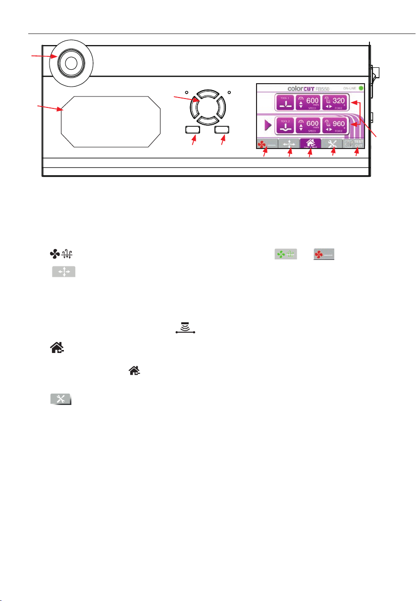
1.6 THE CONTROL PANEL (Overview of Navigation)
①LED Display Displays Tool (Cut/Crease) information and menu parameters.
TOOL 1 - SPEED / FORCE - Controls the speed and force of tool holder 1.
(Generally used to hold the blade for cutting).
TOOL 2 - SPEED / FORCE - Control the speed and force of tool holder 2.
(Generally holds the creasing tool).
Tap on the screen to select each tool, use the HARD keys (left) to adjust values.
② (Fan) Toggles the vacuum fan function on/off [ ] /[ ]
③ /MOVE Takes the Cutter [Of f-Line] and enables your to move the tool
carriage. Used to set the start/origin for cutting and moving the
carriage when placing sheets. After moving the tool carriage, you
must press ENTER twice if you want to define the position as a new
ORIGIN. The MOVE function also enables access to the Sensor light
ON/OFF button (enabling you to see the sensor position).
④ (Home) HOME - Returns back to the main screen.
(When you use the MOVE function or scroll through the menu options, pressing
the [ ](HOME) key leaves the screen and returns to the HOME screen.
(Default Home screen displays: Speed and Force - (for each Tool)
⑤ Menu Scrolls through the machines menu settings/parameters.
Align Tool2 to Tool1 - Sets the distance between tool holder 1 & tool holder 2.
Enabling you to align the CREASE to the CUT . This is not the same as cutting
in the correct position (see SENSOR OFFSET) in your software manual for that!.
Firmware Version - Displays the current installed version of firmwa e.
Menu Mode - Displays the DEFAULT list (above) or ADVANCED list (below)
Work Mode - Cut Plotter - Enables both tool holder 1 and tool holder 2.
- Draw Plotter - Enables tool holder 1 (blade/cut ) only.
Scaling Factor - Scaling for the X direction and Y direction.
- Set at the factory, and typically does not need to be changed.
Factory Reset - Restores ALL factory default settings.
⑥ Test Used to make a Test Cut to check whether the currently selected cutting
conditions are compatible with the media loaded. Tool 2 creases a 45O
rotated square (Like a diamond), then Tool 1 cuts a square around it.
Using a Test Cut you can check Blade Depth and pr essure for cutting
and also confirm if the creasing Tool is perfectly aligned to Cutting Tool.
②
①
⑩
⑤
⑦ ⑧
Offline Enter
⑪
③④⑥
⑨
Intec Printing Solutions - Manual for ColorCut flat bed series FB550 ..................................................................................... Page No: 13
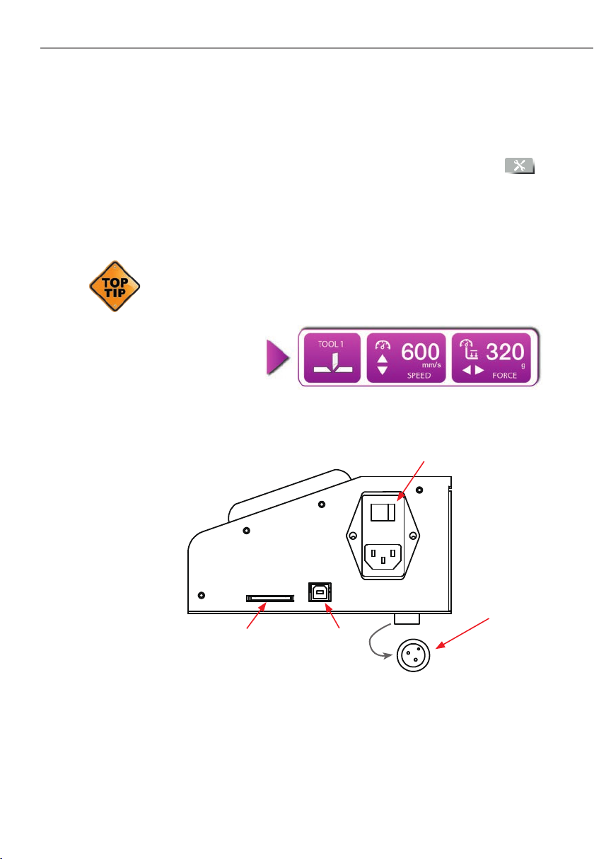
THE CONTROL PANEL (Overview of Navigation)
⑦ Offline When the Default Home screen is displayed, the OFFLINE key takes
the cutter offline. In this mode you cannot send jobs to the cutter.
Pressing the MOVE key will also place the cutter of f-line. You can
move the carriage - r emember after moving the carriage, pr ess ON-
LINE to place the cutter back on-line and enable jobs to be received.
⑧ Enter After setting a function or condition in the MENU options [ ],
press the [ENTER] key to register your setting
⑨ Hard button arrow keys used to INCREASE or DECREASE values on
the LCD panel scr een. Either for TOOL speed/for ce control OR for
changing menu settings or parameters.
The LCD screen will often indicate which key to use to incr ease or
decrease the value. i.e. When Tool 1 is selected, the are displayed
next to the SPEED parameter, indicating you should use the keys.
The symbols ar e displayed next to the FORCE, indicating the
Keys are
used to adjust
these values.
⑩ Emergency switch Cuts the power to the cutter. Depress again to deactivate.
⑪ Tool Recess Convenient place to store tools.
⑫ Power switch Turns the ColorCut Digital Cutter ON/OFF.
⑬ Vacuum pump connector The control cable connector for the Vacuum pump.
⑭ USB interface connector Used to connect the cutter to a computer via the
USB interface.
⑮ SDcard interface connector N/A - This feature is unavailable.
F
1
Reset Set Test
F
2 F
3
Offline
Enter
⑫
⑬
⑭
⑬

Chapter 2 - TOOLS for the Intec ColorCut Flatbed
2.1 Types of cutter blades
2.2 Blade Holder introduction
2.3 Replacing the blade
2.4 Blade length (Adjustment)
Chapter 2
Intec Printing Solutions - Manual for ColorCut flat bed series FB550 ..................................................................................... Page No: 15
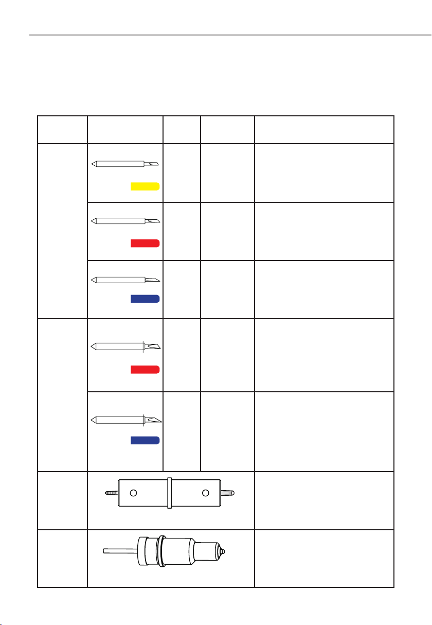
2.1 CUTTER BLADES (An overview of Blade types)
Name Image Angle Blade
Diameter Features and Application
Blade
30O1mm For Film, very soft material, thin
label material.
45O1mm Typically for labels, stickers,
and thin paper/card,
60O1mm
For thick media. The sharply
angled tip provides a longer
cutting edge. Suitable for cutting
media from 0.5 to 1.5 mm thick.*
Circlip
Knife
45O1.4mm
Most packing board up to 500
micron. Circlip provides better
pressure and improves blade
direction changes on dense media.
Suitable for cutting media from 0.25
to 0.5 mm thick
60O1.4mm
For cutting high-intensity reflectiv
film, magnetic media or thick media
The sharply angled tip provides a
longer cutting edge. Suitable for
cutting media from 0.5 to 1.5 mm
thick.* For cutting sandblast rubber.
Creasing
Blade
Bearing-based creasing ball,
double-ended for different width
creasing. Suitable for media ≤500g
Cardboard, corrugated paper
Pen
Holder
Used at setup, to calibrate the offset
between the Optical Registration
Mark sensor (Red light) and the
centre of Tool1 (The blade).
* Maximum cutting depth is defined by the machine type rather than the blade (which is 600 mic ons)
Your cutter comes with a selection of blades. The blades are packed in a foam
packing material. In addition to this there is a colored rubber protective cap. The
yellow caps indicate 30O, red caps indicate a 45O blade while the blue caps are 60O
blades. Be careful when handling the blade as the cutting end is very sharp. Blades
are selected for different applications; a guide is shown below:
Intec Printing Solutions - Manual for ColorCut flat bed series FB550 ..................................................................................... Page No: 16
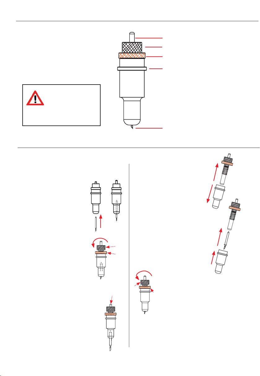
2.2 THE BLADE HOLDER - an introduction
F Exposed Blade
E Flange
D Lock
C Blade Depth Adjustment
B Pin
When handling
cutter blades, be
careful to avoid
cutting your fingers or
other parts of your body.
2.3 Replacing the blade
The blade is a consumable item and
you’ll always get the best quality cut with
a newer blade. Please replace with a
new blade when the cut quality reduces.
For Standard blades
(Without the circlip)
1. Push the blade into the
bottom of the blade holder.
2. Adjust the amount of
exposed (visible) blade
tip to a suitable length by
rotating C the “Adjustment
depth knob” and then tighten
the lock D.
3. Press the push-pin B to
remove the blade from the
blade holder when replacing
blade
For CirClip Blades
1. Unscrew the lower (cover)
part of the blade holder.
2. Insert the Circlip blade into
the inner blade holder. Then
replace the outer cover of the
blade holder;
3. Adjust the amount
of exposed (visible) blade tip
to a suitable length by rotating
C the “Adjustment depth
knob” and then tighten the
lock D.
4. Replace the blade by following the
steps above (Note: You cannot push the
pin as you do with standard blades as the
circlip prevents the blade being removed.
C
D
BD
C

Intec Printing Solutions - Manual for ColorCut flat bed series FB550 ..................................................................................... Page No: 17
2.4 BLADE LENGTH - (Adjustment)
Ⓑ
Blade Depth is a major factor in how well the machine cuts and along with the
downforce / pressure, determines how cleanly the material cuts and how easy or
difficult it will be to ‘weed’ the material. oo much blade depth is as bad as not
enough.
If you have enough blade sticking out to clearly see and feel the tip, it’s
probably too far out. Most new Intec Flatbed cutter owners improperly
install the blade with too much of it protruding from the holder. Set it so that
you can barely see the tip.
Then take the blade holder and manually drag it across a sheet of card or label that
you wish to cut, making a box pattern or square.
Card: Lay a scrap piece of material on a hard work surface with 2 sheets of copier
paper underneath, (not on a nice table in case you cut through paper underneath).
With the blade holder in your hand, press down and cut a circle in the material. Press
down using a moderate amount of force while you cut the circle.
You will not be able to cut through the second sheet of paper when the blade depth is
set correctly. If it cuts through the second sheet then the depth is too much and you
need to retract the blade.
Labels: Lay a scrap piece of material on a hard work surface (not on a nice table in
case you cut through the backing). With the blade holder in your hand, press down
and cut a circle in the material. Press down using a moderate amount of force while
you cut the circle.
Adjust the blade depth so that only traces of the blade’s cut appear on the backing
sheet when a cutting test is performed. You will not be able to cut through the
material backing when the blade depth is set correctly. If it cuts through the backing
then the depth is too much and you need to retract the blade.
The blade length is adjusted by turning the blade adjustment knob.
• To extend the cutter blade, turn the knob in the Ⓐ direction.
• To retract the cutter blade, turn the knob in the Ⓑ direction.
Ⓐ

Chapter 3 - INSTALLATION of your ColorCut Flatbed
INSTALLATION overview
3.1 Basic overview of installation steps
3.2. Parts for assembly
3.2.1 Stand components
3.2.2 Vacuum Pump components
3.3.1 Assembly of the stand and cutter
3.3.2 Connecting the Vacuum pump
3.4. Connecting and Power on the Cutter
3.4.1 Turning on the Cutter
3.4.2 Connecting to a Computer
3.5 Installing Tools
3.6 Calibration of the Creasing Tool to the Cutting Tool
3.7 Calibration

Intec Printing Solutions - Manual for ColorCut flat bed series FB550 ..................................................................................... Page No: 19
3.0.1 OVERVIEW of installation steps
01
02
03
04
05
06
Assemble the stand, mount the intec ColorCut onto the stand. Fit the hose
connectors to the ColorCut engine and Vacuum pump then connect the hose.
Install the supplied ColorCut software for Illustrator or CorelDRAW.
(Refer to your ColorCut Pro Software manual).
Using the supplied USB cable connect the cutter to your PC or Mac.
Then check in the software that the cutter can be seen.
Install the Blade Creasing and Pen Tools.
Turn your cutter on, then calibrate first the Creasing tool position to the
cutting tool. Next refer to your ColorCut pro software manual and set the
offset from sensor to cutting position in your software.
Select your cutting matt, (Felt or Green matt) and load your media .
Use TEST cut to perform a cutting test and adjust blade if necessary.
(Please refer to your ColorCut Prosoftware Manual.
INSTALLATION
START
INSTALLATION
FINISHED
Install ColorCut Flatbed Tools
Connect to your Computer
Install the Software
Assembly
Calibrating the Cutter
Load media and perform test cut

Intec Printing Solutions - Manual for ColorCut flat bed series FB550 ..................................................................................... Page No: 20
3.1 Assembling the Stand, Cutter and Vacuum Pump
Component parts of the vacuum fan pump
1. Left side panel/leg
2. Right side panel/leg
Component parts of the stand
3. Front cross member
4. Rear cross member
6. Castors x 4 free-wheel
7. Bolt, washers, fixing
8. Acoustic pump
9. Flexible hose
10. Silencer (*Option on FB550)
3 4
6 7
2
1
10*
8
9
This manual suits for next models
2
Table of contents
Other Intec Cutter manuals


Popular Cutter manuals by other brands


Toolson
Toolson PRO-RF 620 Original operating instructions

BFluid
BFluid CUT225 manual

SATO
SATO Argox iX4 DX-4200 Series Quick installation guide

TYROLIT Hydrostress
TYROLIT Hydrostress PPH25RR Series Operating instructions and spare parts list

Bush Hog
Bush Hog 1812 Operator's manual

Neschen
Neschen ECOLAM 1650 operating instructions