Intec ColorCut BC480 User manual
Version 3
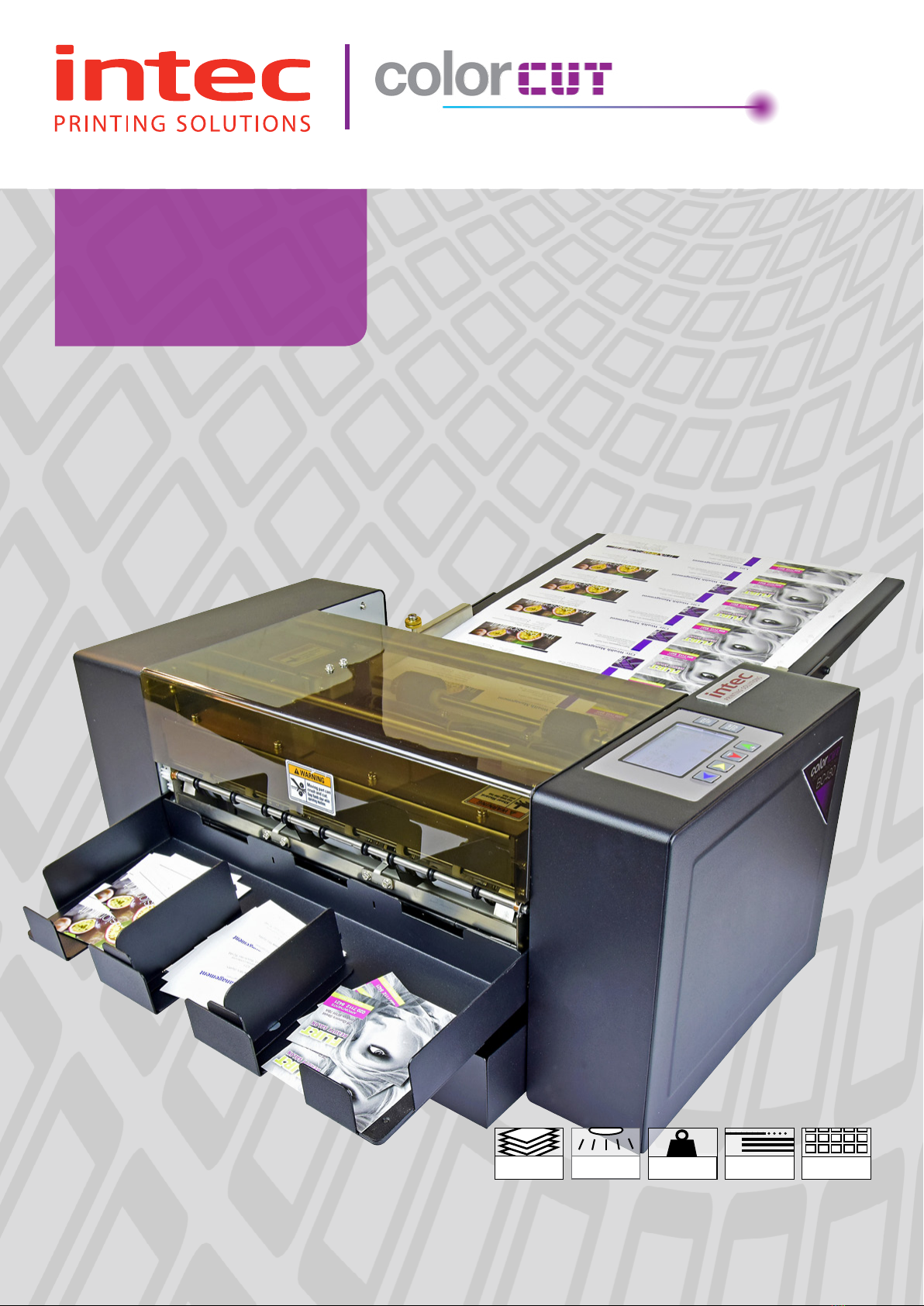
BC480
Business
Card Cutting
User Manual
250 CARDS
96 SECS
PRE-SET
SIZES & TEMPLATES
SENSOR
DUAL MODES
180-350gsm
MEDIA RANGE
FEEDER
AUTO SHEETS

Page 1
Version 1 - January 2019 - TW
Version 3 - September 2020 - TW

Page 2 Page 3
Contents
Chapter One
Important Safety Instructions ......................................... 4
1 Safety Precautions ........................................................................ 4
1-1 Security matters......................................................................... 4
1-2 Warning labels............................................................................ 4
2 Safety Features.............................................................................. 4
2-1 Articles ........................................................................................ 4
2-1-1 Articles and operating limits .................................................. 4
2-1-2 Locking lid - stationary lid ...................................................... 5
3 Product Dimensions...................................................................... 5
Chapter Two
Machine specifications and contents............................. 6
1 . Machine Summary....................................................................... 6
1-1 Main purpose for usage.............................................................. 6
1-2. Machine Specifications ............................................................ 6
1-3 Accessories................................................................................. 7
1-4 Description of machine parts ..................................................... 8
Chapter Three
Set up - Operating, maintenance and troubleshooting11
1. Set up.......................................................................................... 11
1-1 Setting up methods and procedures ....................................... 11
1-2 Paper Feed Tray........................................................................ 12
1-3 Waste Paper Tray...................................................................... 12
1-4 Card Collection Tray ................................................................. 13
1-5 Mains Power.............................................................................. 13
1-6 Placement of machine for operation ....................................... 13
2. Operation .................................................................... 14
2-1 Cutting workflow...................................................................... 14
2-2 Operation panel description ................................................... 15
LCD display description.................................................................. 15
Card option...................................................................................... 16
System option - See Section 2-5-5 ................................................ 16
Manual operate ............................................................................... 16
Language ......................................................................................... 16
Test your cutting mode with a sheet of paper/card....................... 17
Number of cards to be cut.............................................................. 17
2-3 Datum selection ....................................................................... 18
2-3-1 ‘MARK’ printing set up ........................................................ 19
2-4 Cutting modes.......................................................................... 20
2-4-1 Selection of rotary knife cassette (longitudinal knife).......... 20
2-4-2 Cutting modes - paper sizes ................................................ 20
2-4-3 Cutting templates .................................................................. 21
2-4-4 Selecting the cutting mode ................................................... 33
2-5 Parameter settings description .............................................. 33
2-5-1 Cutting quantity .................................................................... 33
2-5-2 Datum selection..................................................................... 33
2-5-3 Card error adjustment method ............................................ 33
1. First cutting compensation ......................................................... 34
2. Mark position compensation ...................................................... 34
3. Card length compensation ........................................................ 35
4. Groove width compensation....................................................... 35
2-5-4 System settings ..................................................................... 36
1. System speed .............................................................................. 37
2. System accuracy compensation ................................................ 37
3. Five column blade width ............................................................. 38
4. Three column blade width .......................................................... 38
5. First cutting compensation ......................................................... 39
6. Mark position compensation ...................................................... 39
7. Groove width compensation....................................................... 39
8. Last card compensation ............................................................ 40
9. Penultimate cards compensation............................................... 40
10. Third from last compensation................................................... 41
11. Subtotal clear ............................................................................ 41
12. Restore factory settings............................................................ 41
8. Firmware version......................................................................... 42
2-5-6 CUSTOM mode card settings ............................................... 42
1. Card width ................................................................................... 44
2. Card length .................................................................................. 44
3. Card rows .................................................................................... 44
4. Card columns .............................................................................. 45
5. First cutting length ...................................................................... 45
6. Mark position length.................................................................... 46
7. Groove width ............................................................................... 46
8. First cutting compensation ......................................................... 46
9. Mark position compensation ...................................................... 47
10. Card length compensation ....................................................... 47
9. Groove width compensation....................................................... 48
2-6 Operating methods and processes........................................ 48
1. Input power.................................................................................. 48
2. Paper settings.............................................................................. 48
3. The left or right position setting of paper................................... 49
2. Feed cutting................................................................................. 49
2-7 Changing the longitudinal cutting cassette .......................... 49
Removing the longitudinal cutter (cutting cassette)...................... 49
Installing the longitudinal cutter (cutting cassette)........................ 50
3. Troubleshooting.......................................................... 51
3-1 Safety cover failure ................................................................... 51
3-2 Jam handling............................................................................. 51
3-3 Crosscutting knife cutting failure ............................................. 52
3-4 MARK’ was not detected......................................................... 52
3-5 Paper too narrow ...................................................................... 53
3-6 Poor feed................................................................................... 54
Support contact information ......................................... 55

Page 4 Page 5
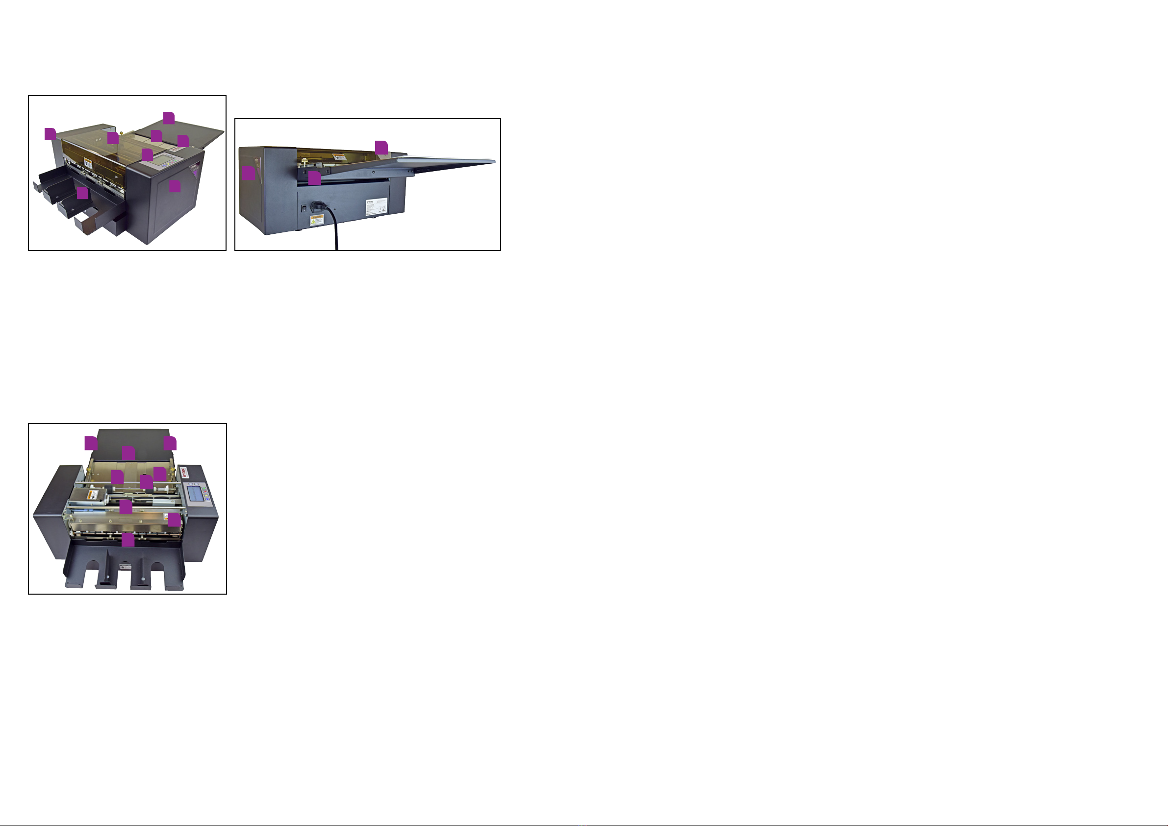
2-1-2 Locking lid - stationary lid
1. Top cover
2. Locked-cover-switch
3. Operate side cover (left cover)
4. Right side cover
5. Front cover
Picture 1-1 front view with feed tray
Picture1-2 back view with catch tray
3 Product Dimensions
Chapter One
Important Safety Instructions
Before installing and using the BC480 please read the following safety insructions. This will help
prevent accidents or loss of equipment and allow you to fully understand the contents and then set
up, operate and maintain the machine in accordance with this.
1 Safety Precautions
1-1 Security matters
In order to prevent accidents, strict compliance with the following matters:
• The machines’s power cord ground wire must be grounded
• Do not connect or disconnect with wet hands, as this will cause an electric shock
• Do not use a damaged plug or lead, as this could cause a fire or an electric shock
• Do not use other voltage and power supply, other than specified, as this will cause a fire and
an electric shock.
• Ensure all hair, neckties, necklaces are kept free of the feeding table to avoid injury
• Do not allow children to use this equipment
• Turn off the power when the machine is not in use
Before any action to remove wate media or to troubleshoot the machine and In exceptional
circumstances, please cut off the power supply.
Please contact your supplier for machine operating instructions should you be unable to follow any
of the manuals instructions or if the machine fails to work.
1-2 Warning labels
The warning labels are placed so you are aware of areas where caution should be taken.
1. Caution electric shock - do not touch machine with wet hands and remove before servicing.
2. Caution moving parts - do not place hands in machine whilst in operation.
3. Caution nipping hands - do not place hands in machine.
Operators should pay attention to the location of the warning labels shown here.
2 Safety Features
In order to prevent accidents, the machine has a cover interlock feature to avoid anyone operating
the machine.
2-1 Articles
2-1-1 Articles and operating limits
The machine has a locking safety cover that prevents items from getting caught in the working
mechanism of the machine.
If the cover is removed during operation the machine will stop working.
840mm
33"
250mm
9.84"
540mm
21.25"

Page 6 Page 7
Chapter Two
Machine specifications and contents
This chapter covers details about the BC480 card cutter and the standard items delivered with it.
1 . Machine Summary
1-1 Main purpose for usage
The cutting of pre-printed business cards, postcards, inserts and greetings cards to pre-set and
custom specified sizes.
1-2. Machine Specifications
Cutting methods Longitudinal cutter (cutting cassette): cut by roll cutter
Horizontal (cross cutting knife): cut by a lateral long cutter
Paper feeding methods Dual rolling auto-paper feeding
paper size A3+(320×480mm); SRA3(320×450mm);
A3(297×420mm) Custom - Use for American size papers
Paper thickness 0.25mm(180g/m²) - 0.35mm(350g/m²)
Plain good quality paper
Cutting speed 250pcs / 96 seconds for 85x55mm card from SRA3 sheets
Cutting sizes Longitudinal: (85/89/90/95) mm
Horizontal: (50/54)mm or 1 to 600mm adjustable
Paper capacity Max.12pcs card (0.35mm thickness) or a total thickness of 3mm
Name card capacity 180g/m² 90×2 (pcs) 350g/m² 70×2(pcs)
Dimensions (wxlxh) 540mm (21.25") × 840mm (33") × 250mm (9.84")
Operating temperature -15º ~ +40º / humidity 35% ~ 70%
Weight 15Kgs
Power supply AC 110~220V / 150w / 50/60HZ / 0.5A
1-3 Accessories
The below accessories are included in the box with the BC480 card cutter. Please check that you
have received all items listed. If anything is missing please inform your supplier immediately.
No. Description Qty Notes
1 User manual 1 Printed booklet
2 Template download card 1 Details download location
3 Collection tray dividers 2 Magnetic dividers
4 Feed tray 1 Feed tray hooks onto rear
5 Paper feed ring 1 Clear rubber ring
6 Feed roller rubbers 3 Flat, black grooved rubbers
7 Blade sharpening stone 1 Fragile - take care
8 Mains power cable 1 Country specific
9 Waste Paper Collection Bin 1 Removal waste paper collector
10 Collection Tray 1 Hooks onto rear of cutter
BC480
Business
Card Cutting
BC480
Business
Card Cutting
Please find a selection of card templates available for download from our website.
• IncludesAdobe®Illustrator®templatesfor:
85mm,89mm,90mmand95mmcardcuttingcassettes
• Producecardsquicklybyaddingyourdesignstotheprovidedtemplates
Please find a selection of card templates available for download from our website.
• IncludesAdobe®Illustrator®templatesfor:
85mm,89mm,90mmand95mmcardcuttingcassettes
• Producecardsquicklybyaddingyourdesignstotheprovidedtemplates
Template Downloads
Template Downloads
ScantheQRcodeorvisitthelinkbelowtoaccessthecorrectpageandthenclicktherequiredBC480
cassettesizetemplatesicon:
https://intecprinters.com/support-downloads/drivers-downloads/colorcut/
ScantheQRcodeorvisitthelinkbelowtoaccessthecorrectpageandthenclicktherequiredBC480
cassettesizetemplatesicon:
https://intecprinters.com/support-downloads/drivers-downloads/colorcut/
14
7
2
58
3
6
9 10
Page 8 Page 9
1-4 Description of machine parts
1. Rear side cover
2. Front side cover
3. Operating panel
4. Safety cover
5. Paper feed tray
6. Double paper feed ring
7. Start button
8. Power cord
9. Paper thickness adjustable indicator
10. Waste paper collection tray
11. Left paper feed panel - adjustable
12. Right paper feed panel - adjustabe
13. MARK sensor arrow for positioning
14. Paper feed rollers
15. Longitudinal knife - interchangeable cassettes - sizes; 85mm (3.34"), 89mm (3.5"), 90mm (3.54")
and 95mm (3.74")
16. Crosscutting knife
17. Anti-static fur
18. Card collection tray
2
6
8
11 12
14
13
16
15
17
18
5
1
2
4
3
7
10
5
9
Page 10 Page 11
Chapter Three
Set up - Operating, maintenance and troubleshooting
This chapter details operating methods and any required maintenance of the BC480.
1. Set up
1-1 Setting up methods and procedures
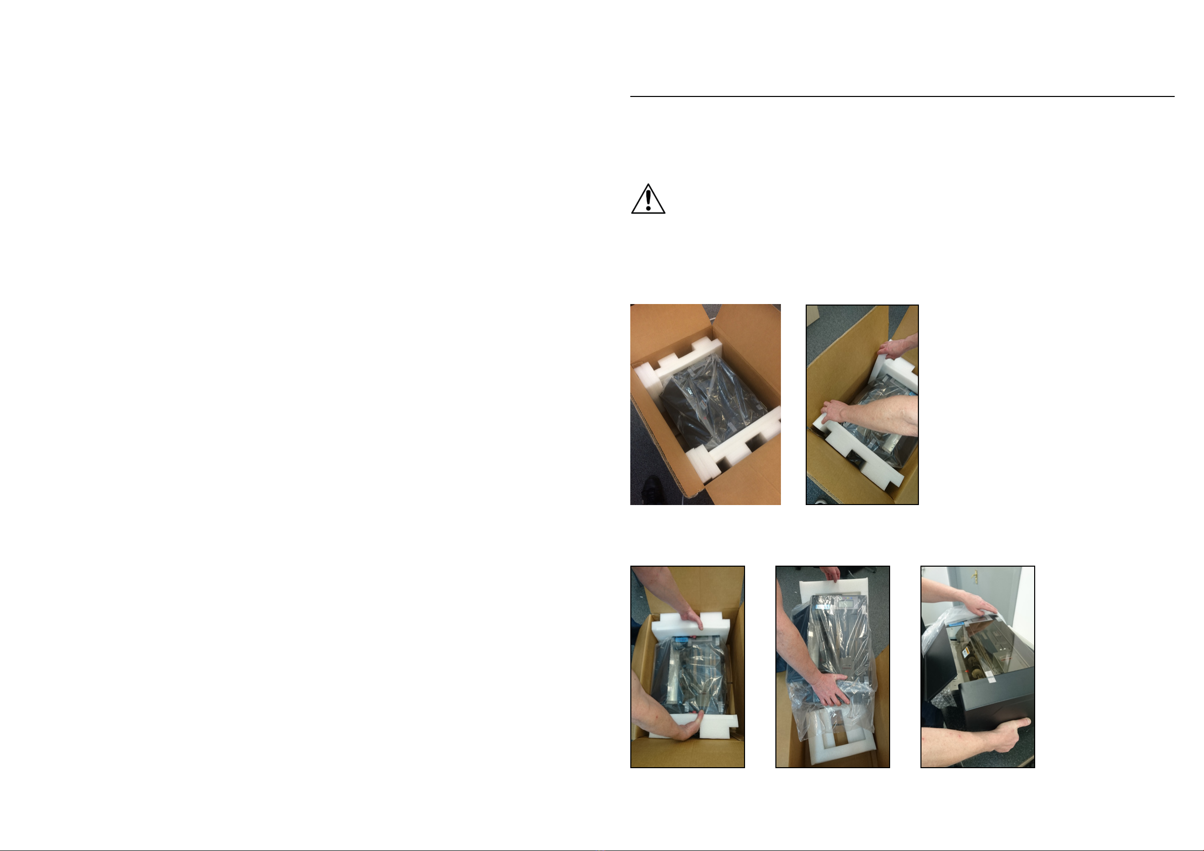
Attention
The BC480 is 15kgs in weight. This can be lifted from its box by one person however, it is advised
that it should be lifted from its box by 2 people.
Remove the BC480 as specified below:
Open the box and remove the top cardboard and foam packing as shown below.
Place you hands either side of the white foam inserts, these should be lifted out with the unit and
remove the unit placing it on a stable surface. Picture 1.
Picture 1 Picture 2 Picture 3
Once out of the box and placed on a stable surface, carefully, and whilst supporting the machine
remove the white foam ends and outer plastic bag. Picture 2 and 3.

Page 12 Page 13
Once in place and on a stable surface check contents.
The machine contains wrapped items, as listed in Chapter 2. 1-3 Accessories section, in the waste
tray.
Remove all the items and check all the contents are there.
Once you have confirmed that all the items are received please put the BC480 together as follows:
1-2 Paper Feed Tray
Find the paper feed tray and hook onto the holding pins.
The tray has adjustable feed guides that can be secured in place by tightening the screws on either
side of the tray - ensure these are closed up to your paper edges but not too tight!
1-3 Waste Paper Tray
Install the waste paper tray in the back of the machine, making sure tray is fully inserted into the
aperture.
1-4 Card Collection Tray
Install the card collection tray onto the holders for this:
After the card collection tray has been secured in place, add the card dividers - these are magnetic
and adjustable.
1-5 Mains Power
Now put your mains power cable in its input socket and plug into a mains power source.
!
Attention: Make sure the main covers magnetic interlock switch is fully connected
In order to remove the static charge must be grounded.
!
Attention: In case of electric leakage, be careful electric shock
Make sure power switch be turned on.
1-6 Placement of machine for operation
Please use the machine in the following places:
•Onastablesurface
•Inawell-ventilatearea
•Ensureareaaroundthemachineisfreefromdebris
The machine is made of precision machinery and electronic components and therefore needs
to be located in a suitable place for use.
Please avoid the following locations:
•Directsunlight
•Areasofhighhumidity
•Keepawayfromsourcesofignition
•Placesthatcanbecomepronetomoisture
Page 14 Page 15
•Closetoheatingandcoolingsources
•Vibrationofworksurface
!
Attention
•Don’tputanyotherelectricalplug,otherthanwhathasbeenprovided,intoelectricaloutlet
•Pronetostatic-youshouldusestaticshieldandhumidifier
•Don’tputthemachineonatablethatissmallerthanitsfootprint
2. Operation
2-1 Cutting workflow
This flowchart shows you the process for machine usage.
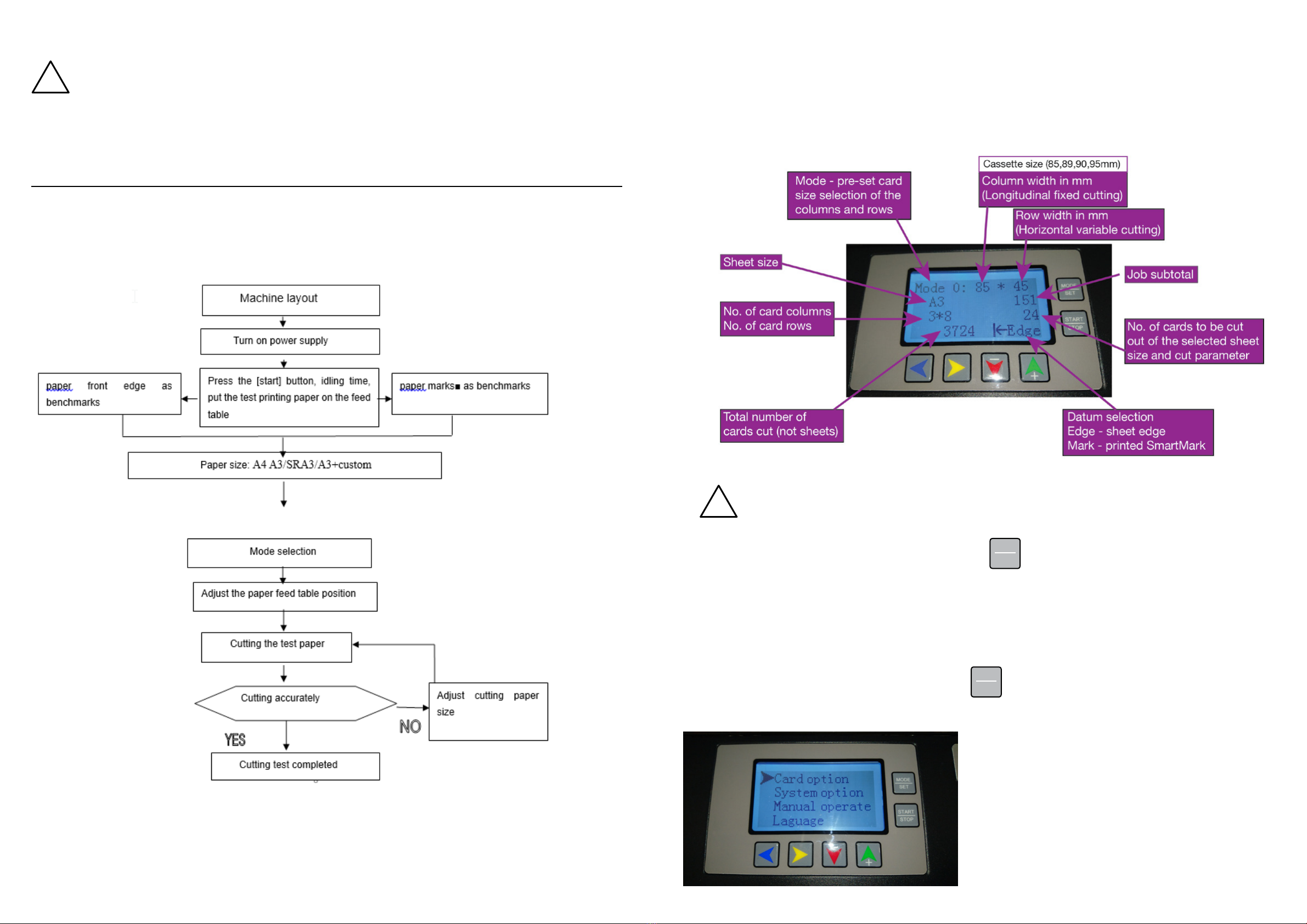
2-2 Operation panel description
LCD display description
Initial understanding of the LCD panel is important. Please take a little time to navigate yourself
through the buttons and display before completing any work.
!
When the BC480 is turned on it will go into the last mode used.
With the BC480 turned on and in standby press the
MODE
SET button. This will change your cutting
Mode number (0-9). The cutting mode is the preset COLUMN width size in mm and is defined by the
cassette delivered with the BC480 and ROW length - this figure is variable and dependant on the
card size you would like to cut.
Press this button to understand how the modes change and watch the card sizes change - this does
not change your sheet / paper size. The modes are explained in Section 2-4.
After pressing through the modes now press the
MODE
SET for 3 seconds. This will take you into the
setup menu as shown below:

Page 16 Page 17
DO NOT make any changes here yet - this will be explained later in the chapter.
When in this menu these are the options available:
Card option
Allows you to make changes to the card preset mode (A3, A3+, SRA3) you have selected:
• First cutting compensation
• Mark position compensation
• Card length compensation
• Groove width compensation
Note: If you are in CUSTOM mode you will also so these options:
• Card width
• Card length
• Card rows
• Card columns
• First cutting length
• Mark position length
• Groove width
• First cutting compensation
• Mark position compensation
• Card length compensation
• Groove width compensation
Note: This is an individual card changes only. The Card Option menu DOES NOT make a universal
change to all set ups.
System option - See Section 2-5-5
Allows you to make changes to the universal set up of the BC480. This will make adjustment to all
the set ups universally and these include:
• System speed - from 1 to 9 but we advise you do not set this to more than 8 as it can have a
detrimental affect on your settings. The default setting is 6.
• System accuracy compensation
• Five column blade (longitudinal) width - for 5 card cassette
• Three column blade (longitudinal) width - for 3 card cassette
• First cutting compensation
• Mark position compensation
• Groove width compensation
• Last card compensation
• Penultimate card compensation
• Third from last card compensation
• Subtotal clear
• Restore factory settings
• Firmware version
Manual operate
This allows you to manually operate the BC480 - use the arrows to move the paper forwards,
backwards and up and down. You can use this mode when you have a paper jam.
Language
This allows you to select either English or Chinese.
To navigate through the 4 options shown above use the and arrows. Once you have
selected the menu the you would like make changes in press the
MODE
SET and this will take you to
the sub menus associated with the main menus (card option, System option, Manual operate,
Language). To come out of the sub menus and back to this main window press the
MODE
SET button
again and then press the
MODE
SET for 3 seconds to return you to standby mode.
Test your cutting mode with a sheet of paper/card
Now take some paper/card and place this in the feed tray.
Note: You can place up to 3mm stack height in the BC480 feed tray (approximately 10 sheets of
250gsm Mondi ColorCopy paper)
Press the button until you see Edge on the LCD panel.
Once in position press the
START
STOP button. This will cut a sheet using the mode you have selected on
the LCD panel.
We will continue to look at the LCD screen description.
To change your sheet / paper size press the arrow. This will take you through the sheet size
options available to you.
• A3 (297mm x 420mm)
• A3+ (320x480mm)
• SRA3 (320 x 450mm)
• A4 (only available in selected territories - do not use)
• CUSTOM (set for American paper sizes if purchased in America only)
Now press the button and this will now provide you with your Datum selection - explained in
section 2-3.
Number of cards to be cut
Take a look at your initial Mode selection and this will tell you how many cards are to be cut from the
sheet size and mode you have selected.
By pressing the and button you can set the amount of cards to be cut.
Note: The Mode you have showing will determine how many cards will be cut from a sheet of
paper.
By continuing to press the button you will incrementally increase the number of cards to be
cut, up to a maximum of 10 and then the system takes you to AUTO mode. To reduce the number of
cards to be cut press the button.
EXAMPLE: If you have 3 sheets of 24 cards to cut press the twice and it will show 72. This is
the amount of cards to be cut from 3 sheets of paper. Place 3 sheets in the feed tray and press the
START
STOP button. The BC480 will cut the 3 sheets and stop after this action.
AUTO - If you leave the BC480 in AUTO it will continue to cut sheets until there are no more sheets
in the tray to feed. The BC480 will try to take sheets for another 2 seconds and will then stop.
Page 18 Page 19
(2) LCD display description
Turn on power supply. The BC480 will initialize and go into standby mode - the LCD display will
show the default mode selection - be sure to change your mode and paper size settings to your
desired card cutting options.
2-3 Datum selection
There are two ways of cutting sheets; using the EDGE of the sheet of paper as your initial guide
point or using a printed ‘MARK’ that the internal mark sensor will read to position its cuts.
Note: The ‘MARK’ option is particularly useful when printing with a digital printing press or copier
because it allows for any sheet printing adjustments.
On the control panel the ‘Datum Selection’ can be selected by pressing the button to choose
which option you would like to use.
Edge Edge: cutting from the front of the sheet as a benchmark
Mark Mark: using a printed ‘MARK’ to position the cuts on sheet
The machine has preset cutting parameters and will always default to EDGE unless you are using
the CUSTOM mode and some of the CUSTOM modes have ‘MARK’ detection set as a default - see
section 2-4 Cutting modes.
i Please be sure to note what Datum option you are using before you press the
START
STOP button to
cut your sheets.
Note: As you scroll through the modes you will need to ensure that you check which datum option
is selected for a particular preset.
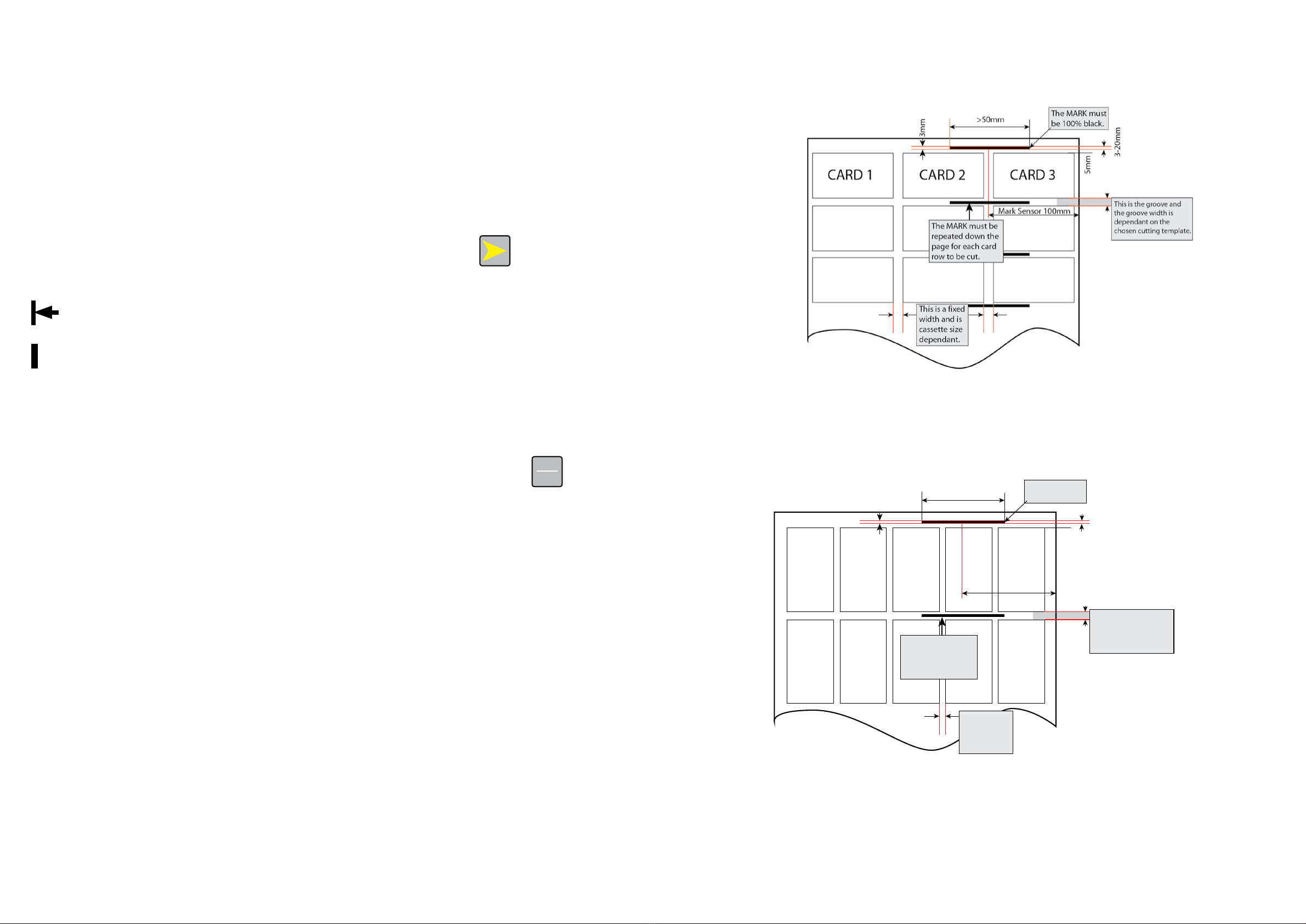
2-3-1 ‘MARK’ printing set up
This is the template set up if you are using A3 paper and have a 3 column cassette:
This is the template set up if you have A3 paper and a 5 column cassette:
Mark Sensor 100mm
>50mm
5mm
3-20mm
This is your groove and
the groove width is
dependant on the
chosen cutting template.
The MARK must be
repeated down the
page for each card
row to be cut.
The MARK must
be 100% black
3mm
CARD 1
CARD 2
CARD 3
CARD 4
CARD 5
This is a fixed
width and is
cassette size
dependant.
The ‘MARK’ on the templates provided are designed to work with the set ups as described in the
manual and those available for download from the Intec website.
If you are creating your own templates be sure to note where the ‘MARK’ falls in relation to the
sensor arrow marks for your chosen cutting cassette on the feed table and in relation to how you
have the paper feed guides set.

Page 20 Page 21
2-4 Cutting modes
2-4-1 Selection of rotary knife cassette (longitudinal knife)
85mm cassette - 3 column cutting widths 85mm - delivered as standard for EMEA countries
89mm cassette - 3 column cutting width 89mm - delivered as standard for the Americas
90mm cassette - 3 column cutting width 90mm - special order
90mm cassette - 3 column cutting width 95mm - special order
55mm cassette - 5 column cutting width 55mm - only available in selected territories
54mm cassette - 5 column cutting width 54mm - only available in selected territories
Indentation cassette - only available selected territories
Perforation cassette - only available selected territories
If you require anything different from the standard cassette provided with the machine, please
specify this at time of order.
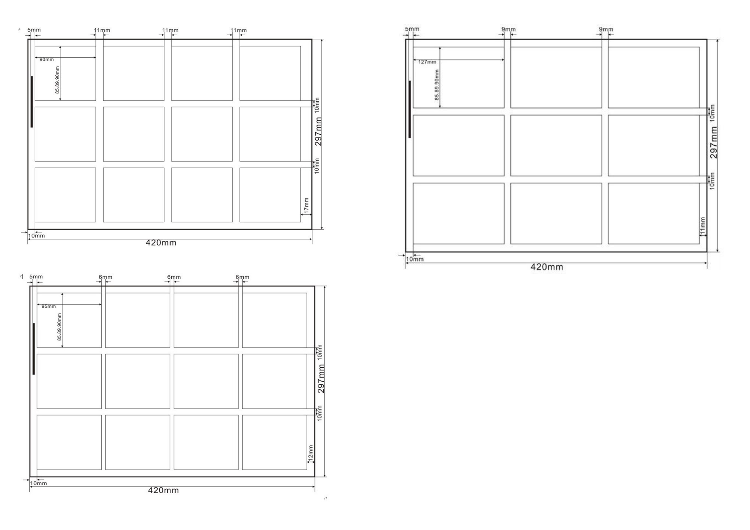
2-4-2 Cutting modes - paper sizes
(1) Paper size: A3+ (320×480mm)
Mode 0: 89x45mm; select 89mm cassette - 3 columns and 9 rows - total 27 cards
Mode 1: 89x50mm; select 89mm cassette - 3 columns and 8 rows - total 24 cards
Mode 2: 89x54mm; select 89mm cassette - 3 columns and 8 rows - total 24 cards
Mode 3: 89x90mm; select 89mm cassette - 3 columns and 5 rows - total 15 cards
Mode 4: 55x85mm; select 55mm cassette - 5 columns and 5 rows - total 25 cards
Mode 5: 55x89mm; select 55mm cassette - 5 columns and 5 rows - total 25 cards
Mode 6: 55x90mm; select 55mm cassette - 5 columns and 5 rows - total 25 cards
Note: These are default presets out of the box. If you have a different cassette size you can
change these presets to suit the cassette size you are using. Please see section 2.5 to do this.
(2) Paper size: SRA3 (320×450mm)
Mode 0: 89x45mm; select 89mm cassette - 3 columns and 8 rows total - 24 cards
Mode 1: 89x50mm; select 89mm cassette - 3 columns and 7 rows - total 21 cards
Mode 2: 89x54mm; select 89mm cassette - 3 columns and 7 rows - total 21 cards
Mode 3: 89x90mm; select 89mm cassette - 3 columns and 4 rows - total 12 cards
Mode 4: 89x95mm; select 89mm cassette - 3 columns and 4 rows - total 12 cards
Mode 5: 89x127mm; select 89mm cassette - 3 columns and 3 rows - total 9 cards
Note: These are default presets out of the box. If you have a different cassette size you can
change these presets to suit the cassette size you are using. Please see section 2.5 to do this.
(3) Paper size: A3 (297×420mm)
Mode 0: 89x45mm; select 89mm cassette - 3 columns 8 rows total 24pcs cards
Mode 1: 89x50mm; select 89mm cassette - 3 columns 7 rows total 21pcs cards
Mode 2: 89x54mm; select 89mm cassette - 3 columns 7 rows total 21pcs cards
Mode 3: 89x90mm; select 89mm cassette - 3 columns 4 rows total 12pcs cards
Mode 4: 89x95mm; select 89mm cassette - 3 columns 4 rows total 12pcs cards
Mode 5: 89x127mm; select 89mm cassette - 3 columns 3 rows total 9pcs cards
Note: These are default presets out of the box. If you have a different cassette size you can
change these presets to suit the cassette size you are using. Please see section 2.5 to do this.
(4) Paper size: CUSTOM - use for American paper sizes 12"x17" and 12"x18"
Mode 0: CUSTOM (EDGE detection set as default)
Note for USA users: Preset - 12"x17" for 3.5" x 2" cards and no groove, so only to be used with
non-bleed. See templates provided.
Mode 1: CUSTOM (EDGE detection set as default)
Note for USA users: Preset - 12"x18" for 3.5" x 2" cards and can be used for non-bleed and cards
with bleed. See templates provided.
Mode 2: CUSTOM (EDGE detection set as default)
Note for USA users: Preset - 12"x18" for 3.5" x 5" cards and can be used for non-bleed and cards
with bleed. See templates provided.
Mode 3: CUSTOM (EDGE detection set as default)
Note for USA users: Preset - 12"x18" for 3.5" x 8" cards and can be used for non-bleed and cards
with bleed. See templates provided.
Mode 4: CUSTOM (MARK detection set as default)
Note for USA users: Preset - 12"x18" for 3.5" x 8.5" cards and can be used for non-bleed and
cards with bleed. ALSO this preset on the unit defaults to MARK datum detection all the time,
so you have to be change to EDGE before you cut. Press the yellow arrow to change the datum
selection. See templates provided.
Mode 5: CUSTOM (MARK detection set as default)
Note for USA users: Preset - 12"x18"for 3.5"x 2"cards and can be used for non-bleed and cards
with bleed.
Mode 6: CUSTOM (MARK detection set as default)
Note for USA users: Preset - 12"x18"for 3.5"x 5"cards and can be used for non-bleed and cards
with bleed. See templates provided.
Mode 7: CUSTOM (MARK detection set as default)
Note for USA users: Preset - 12"x18"for 3.5"x 8"cards and can be used for non-bleed and cards
with bleed. See templates provided.
Mode 8: CUSTOM (MARK detection set as default)
Note for USA users: Preset - 12"x18"for 3.5"x 8.5"cards and can be used for non-bleed and
cards with bleed. See templates provided.
Mode 9: CUSTOM (MARK detection set as default)
Note: There are no presets for this mode - please use this option for testing purposes.
Note: These are default presets out of the box. If you have a different cassette size you can change
these presets to suit the cassette size you are using. Please see section 2.5 to do this.
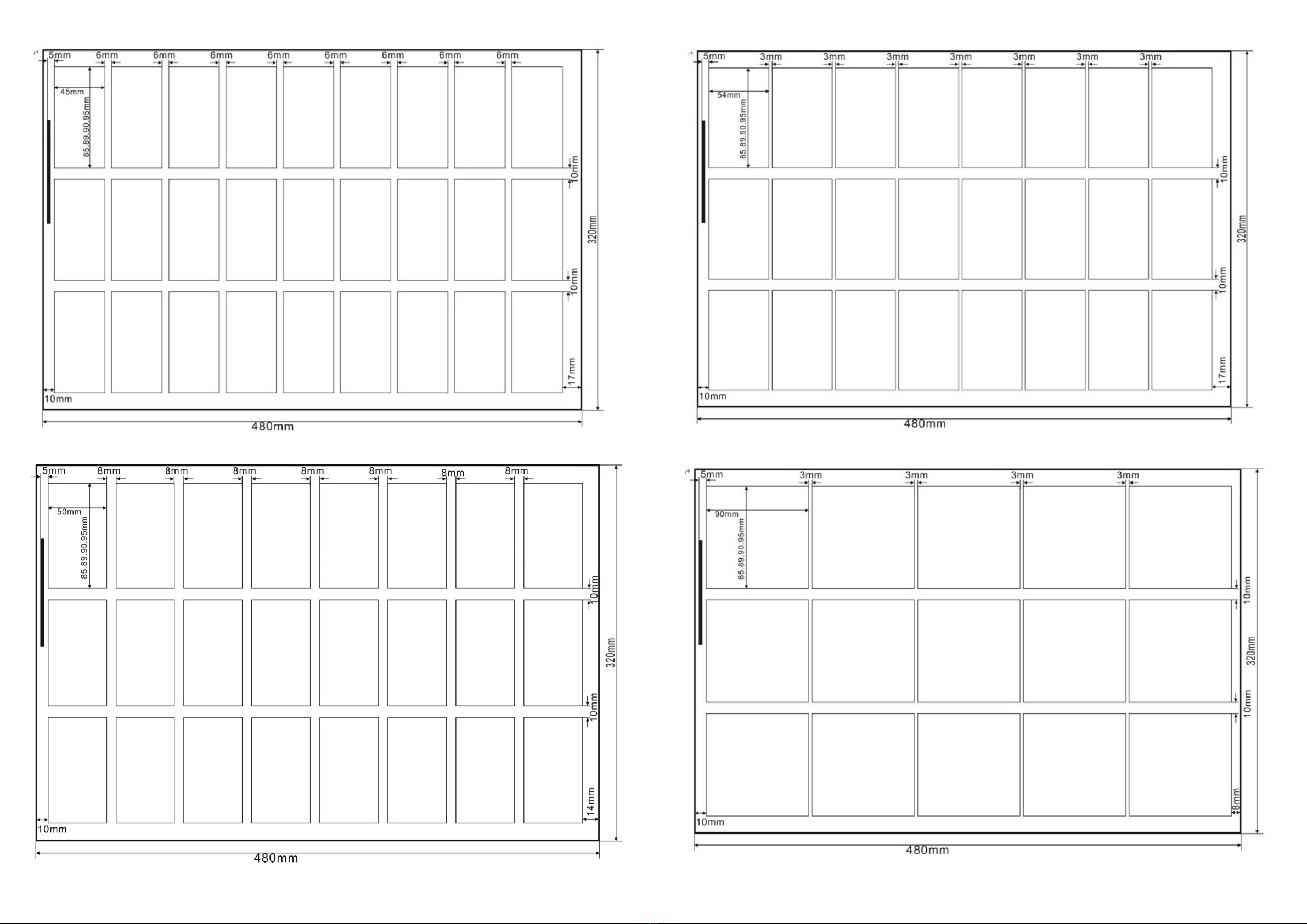
2-4-3 Cutting templates
Cutting templates for A3+, SRA3, A3 and CUSTOM sheet sizes can be found on the Intec website
in our support and downloads section: https://intecprinters.com/support-downloads/drivers-
downloads/colorcut/
i This information has been provided on a template download card that is shipped with the
BC480.
Page 22 Page 23
• A3+ MODE 0
• A3+ MODE 1
• A3+ MODE 2
• A3+ MODE 3
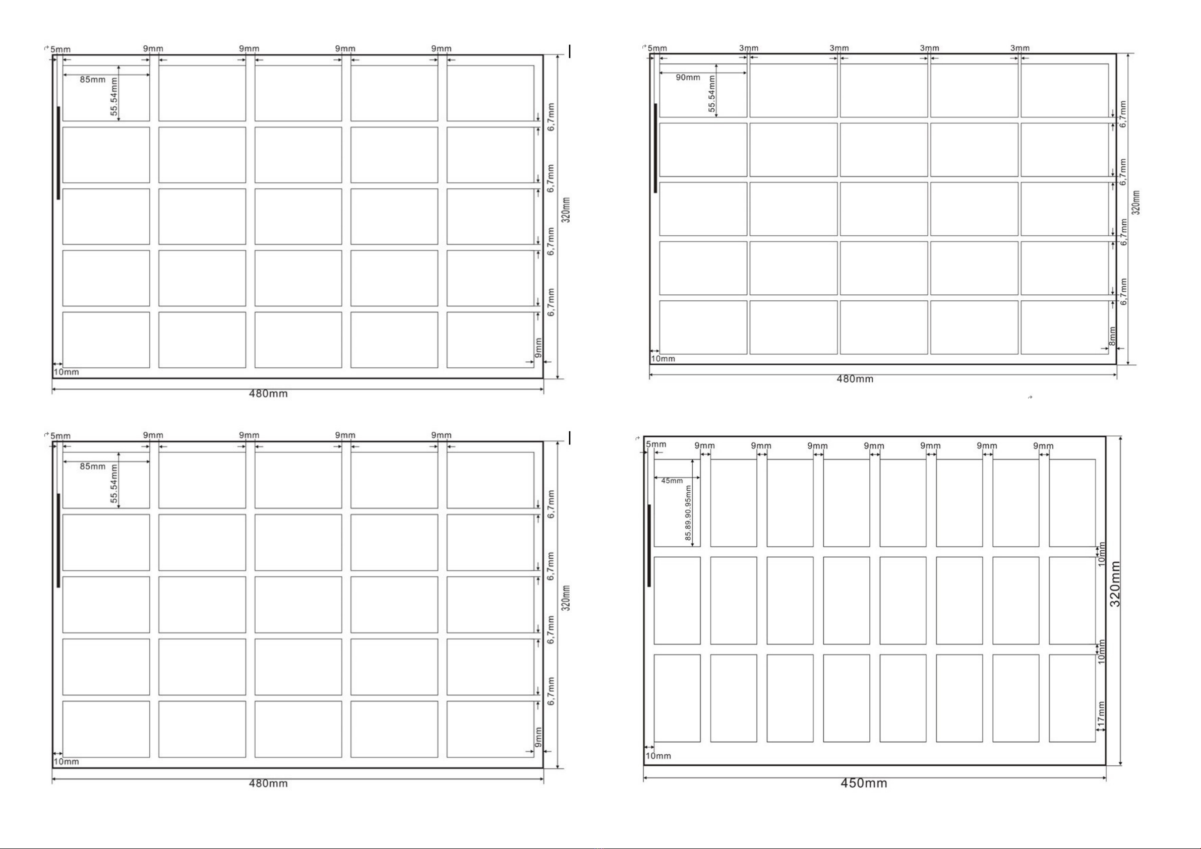
Page 24 Page 25
• A3+ MODE 4
• A3+ MODE 5
• A3+ MODE 6
• SRA3 MODE 0
• SRA3 MODE 1
Page 26 Page 27
• SRA3 MODE 2
• SRA3 MODE 3
• SRA3 MODE 4

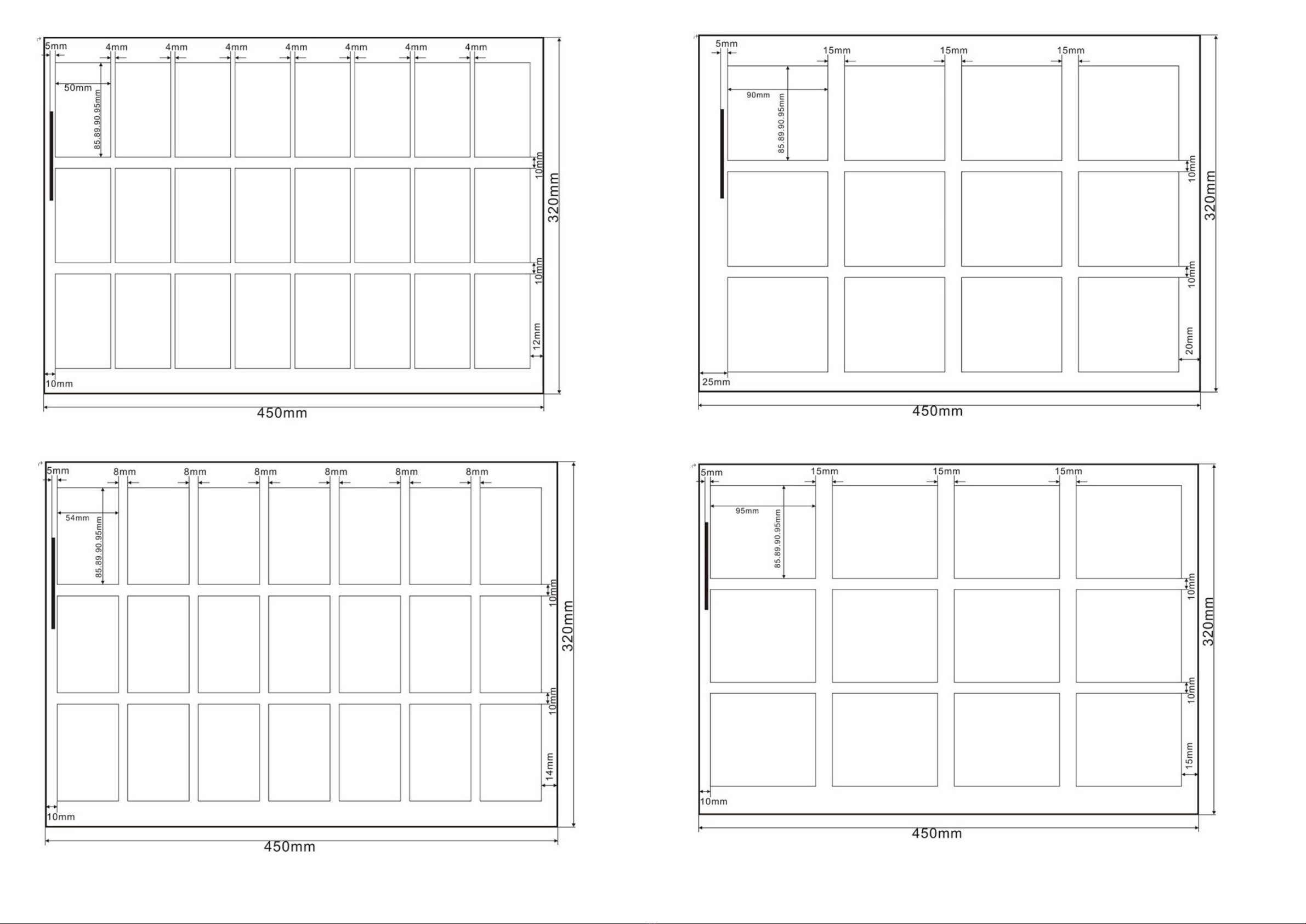
Page 28 Page 29
• SRA3 MODE 5
• A3 MODE 0
• A3 MODE 1
• A3 MODE 2
Page 30 Page 31
• A3 MODE 3
• A3 MODE 4
• A3 MODE 5

Page 32 Page 33
Custom mode,C-3 column cassette -XX rotary knife - paper width: 297--320mm
Custom mode, C-5-column cassette - XX rotary knife - paper width: 297--320mm
Before starting to use the BC480 the following menus are available to you for adjustment of the
machine.
These can be accessed by pressing down the MODE/SET
MODE
SET button for 3 seconds.
The next few pages will explain how these options allow you to adjust the machine settings.
2-4-4 Selecting the cutting mode
This option enables you to access the correct card cutting templates for the sheet / paper size you
are cutting and the number of cards to be cut as detailed in section 2-4-2.
To change the preset card cutting options press the MODE/SET
MODE
SET button this will scroll you
through the cutting options available for the selected paper/ sheet size you have chosen. To change
sheet / paper size use the button. Scroll through until you reach your desired paper sizes and
card preset. This will be displayed on the screen until you change it again or turn the BC480 off.
2-5 Parameter settings description
2-5-1 Cutting quantity
This menu allows you to set the total amount of cards required to be cut.
This option is ideal if you have a stack of sheets that all require the same cutting template as you
can stack these in the feed tray and set the amount of cards to be cut using this function and leave
them to cut automatically.
So if your sheet has 21 cards to be cut multiply this with the amount of sheets you have (up to 3mm
stack height) and set that number on the machine.
In the standby mode, press the or to reach the required quantity up to a multiple of 10.
21 cards x 10 sheets = 210. After which if will go to AUTO.
AUTO allows for continuous feed of all stacked sheets in the tray and until the tray is empty. When
there are no more sheets to present to the cutter, and the tray becomes empty, the cutter will stop.
2-5-2 Datum selection
Press button in standby mode, to switch between Edge or Mark detection. This is
dependent on the template you have chosen to use.
2-5-3 Card error adjustment method
When you receive an error in the size of you cut cards (preset modes), you have a number of
adjustable options to help with the accuracy of these sizes. These include;
• First cutting compensation
• Mark position compensation
• Card length compensation
• Groove width compensation
These menus can be found under the CARD OPTION menu and is specific to the preset (not
custom) card mode you have selected at the time.
To access these menus, press and hold the
MODE
SET button for 3 seconds. This will enter the setup
menu, the LCD display:
Page 34 Page 35
Press or button to move the arrow selection cursor to the CARD OPTION menu and
press the
MODE
SET button to enter the sub menus as listed.
To navigate through the sub menus for card option press the button.
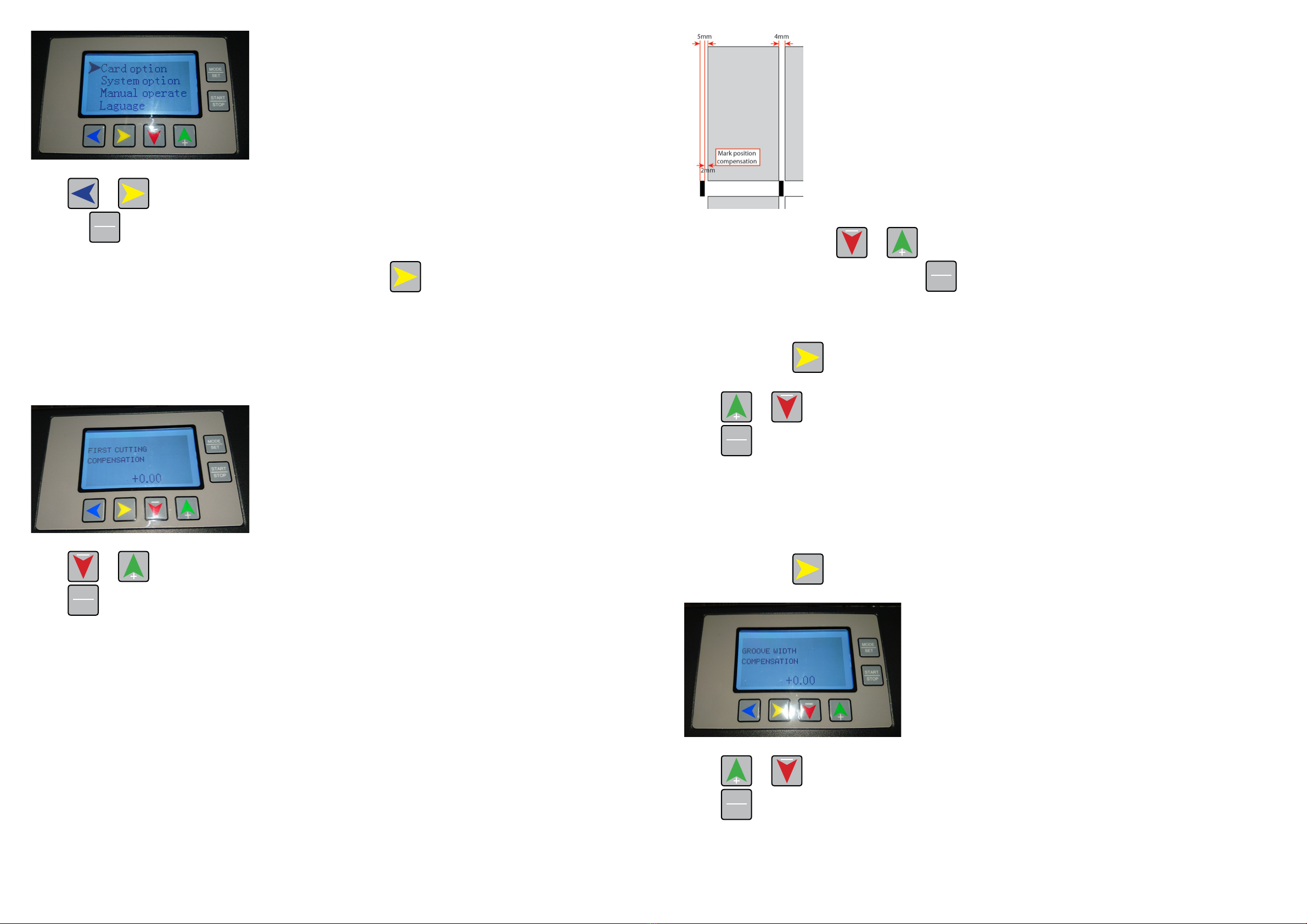
1. First cutting compensation
This is where the first cut is placed on your card.
All the card presets (except CUSTOM) default to Edge cutting. Datum selection is chosen our
templates will have this set to 10mm as a default.
LCD display:
Press or buttontochangethecompensationvalue(-5.0—+5.0mm(
Press
MODE
SET button and return to previous menu.
2. Mark position compensation
This refers to the gap between the bottom of the ‘MARK’ and the edge of where the next card is to
be cut.
Here our example shows a 2mm gap between the ‘MARK’ and the edge of card to be cut.
To adjust this value press or button, until the LCD displays your required measurement.
Once your measurement is set press the
MODE
SET button to return to previous menu.
3. Card length compensation
Continue to press button, until you see Card length compensation in the LCD display.
Press or buttonforcompensationsettingof-3.0—+3.0mm(
Press
MODE
SET button and return to previous menu.
4. Groove width compensation
Your groove width is the gap (measurement in mm) between you card rows. You can apply a
compensation to your width. This is a variable measurement and is dependant on the card template
you have selected and the therefore the card mode.
Continue to press button, until the LCD display:
Press or buttonforCompensationsetting(-3.0—+3.0mm(
Press
MODE
SET button and return to previous menu

Page 36 Page 37
2-5-4 System settings
Under normal circumstances the BC480 will have been set up prior to shipping and you will not have
to make any changes under the system settings.
Should you wish to only change an individual card setting please do this under the CARD OPTION
menu specific to the card mode selected.
!
Attention:
Any changes made under the system settings will change the values for all preset card modes.
These are universal changes.
The options available under the system settings are:
• System speed
• System accuracy compensation
• Five column blade (longitudinal) width - for 5 card cutting cassettes
• Three column blade (longitudinal) width - for 3 card cutting cassettes
• First cutting compensation
• Mark position compensation
• Groove width compensation
• Last card compensation
• Penultimate card compensation
• Third from last card compensation
• Subtotal clear
• Restore factory settings
• Firmware version
From standby mode, press
MODE
SET and hold the button for 3 seconds to enter the setup menu, the
LCD will display:
To navigate around the menus press the or buttons to move the cursor to system
selection. Once you have selected the System option menu press the
MODE
SET button which will take
you to the sub menus.
To navigate around the following sub menus use the button.
i To easily make changes to a measurement values and when in the menu you would like to
change, press the
START
STOP and this will add a small arrow above the measurement values as shown
below. Keep pressing until the arrow falls above the measurement you want to change and use the
or buttons to change the value until you are finished.
1. System speed
This menu sets the speed of cutting of your sheets.
Changing the system speed can affect the cutting accuracy and positioning of your cuts.
The selectable options are 1-9 . 1 being the slowest and 9 the fastest setting.
As an example and using an SRA3 sheet for 85mm x 54mm cards (21 cards to cut) the system on
setting 1 will take 9 seconds to cut the sheet and on 9 it takes 7 seconds to cut the sheet.
The BC480 will have been programmed and tested prior to shipping and so the value set in this
menu should not be changed. However, if it has to be changed, we advise you do not set this to
more than 8.
If you need to change the speed setting this can be done by using the or buttons.
2. System accuracy compensation
This refers to the scaling
This is set prior to shipping and should not be adjusted.
Table of contents
Popular Office Equipment manuals by other brands


Koplus
Koplus MILLI STAND Assembly instructions

silen
silen CHATBOX Assembly manual

LDI Spaces
LDI Spaces Safco Onyx 6453 Assembly instructions

Reiner
Reiner P1-MP2-RD instructions

3-form
3-form SimpleSpec 200.64 installation manual

Herman Miller
Herman Miller FT194.A Installation and Disassembly for Recycling Instructions

PG BISON
PG BISON OFFICE FURNITURE BLUM FLATPAX Assembly guide

J.Burrows
J.Burrows Stilford JBSHBB18WW Assembly instructions

Epson
Epson SC-F9300 series Setup guide

Uplift Desk
Uplift Desk ACC071 quick start guide

hushoffice
hushoffice hushfree.M HUS-AP-002 Maintenance and safety manual

Koplus
Koplus HOP DESK Assembly instructions