Integratech ECULED212-1H User manual
DATASHEET
ECULED212-1H
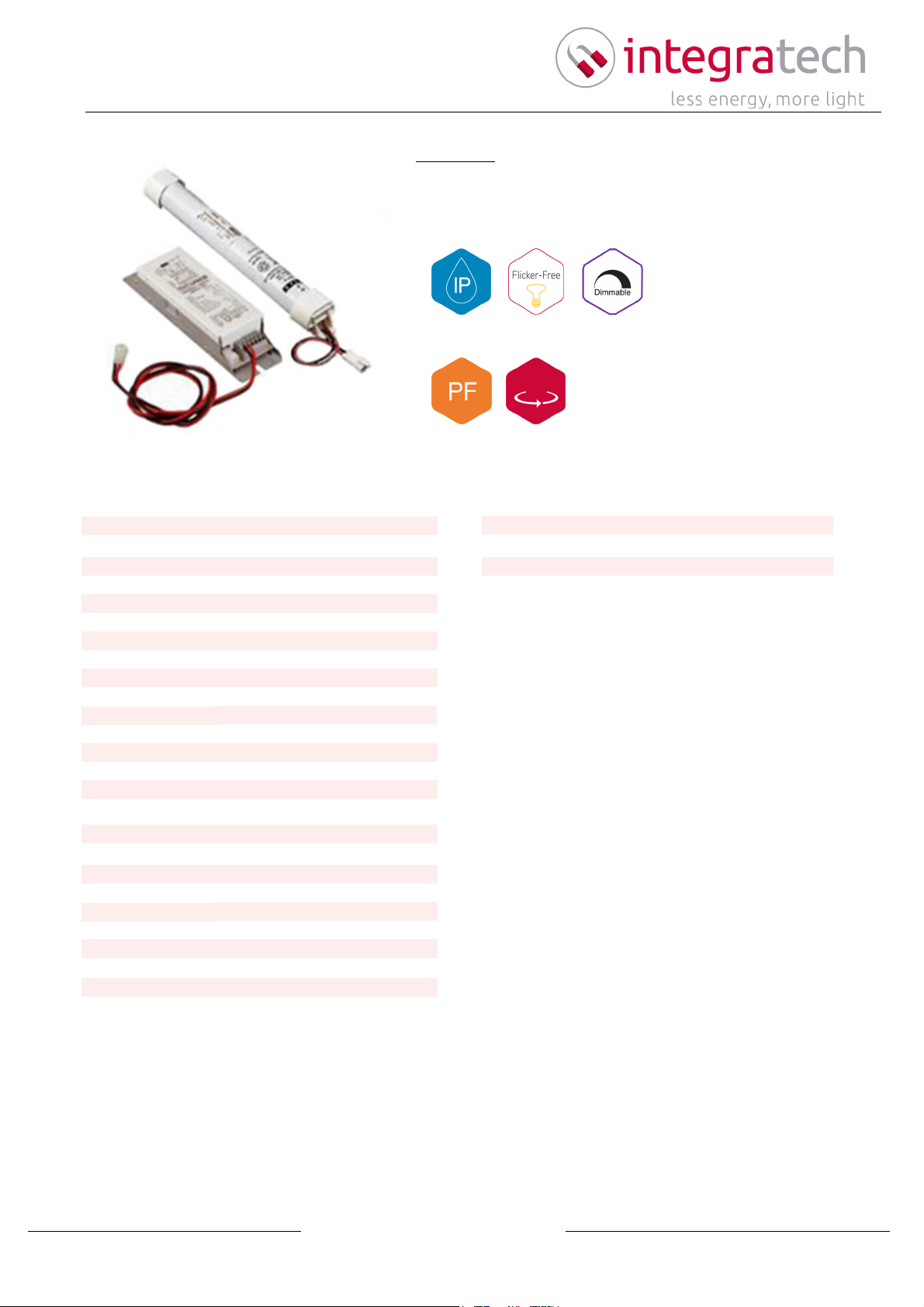
Emergency unit 1 hour 3,6V 1,7Ah max 45V output for LED panel or downlighter, non-permanent / permanent.
Switchable. Warranty 2 years, 1 year on batteries.
Emergency unit for Leddriver 1h max 45Vdc
Description:
IP20
2 YEARS
YES NO
Reference ECULED212-1H
EAN code 5420076206529
Weight (kg) 0,354
Power factor
IP value IP20
Working temp. (°C) 0~+45
Warranty (year) 2
System power (W) 50
Driver output (V) 45
Driver output (mA)
Frequency (Hz) 50/60
Input voltage (Vac) 230
Energy class
Dimmable no
Connection cable
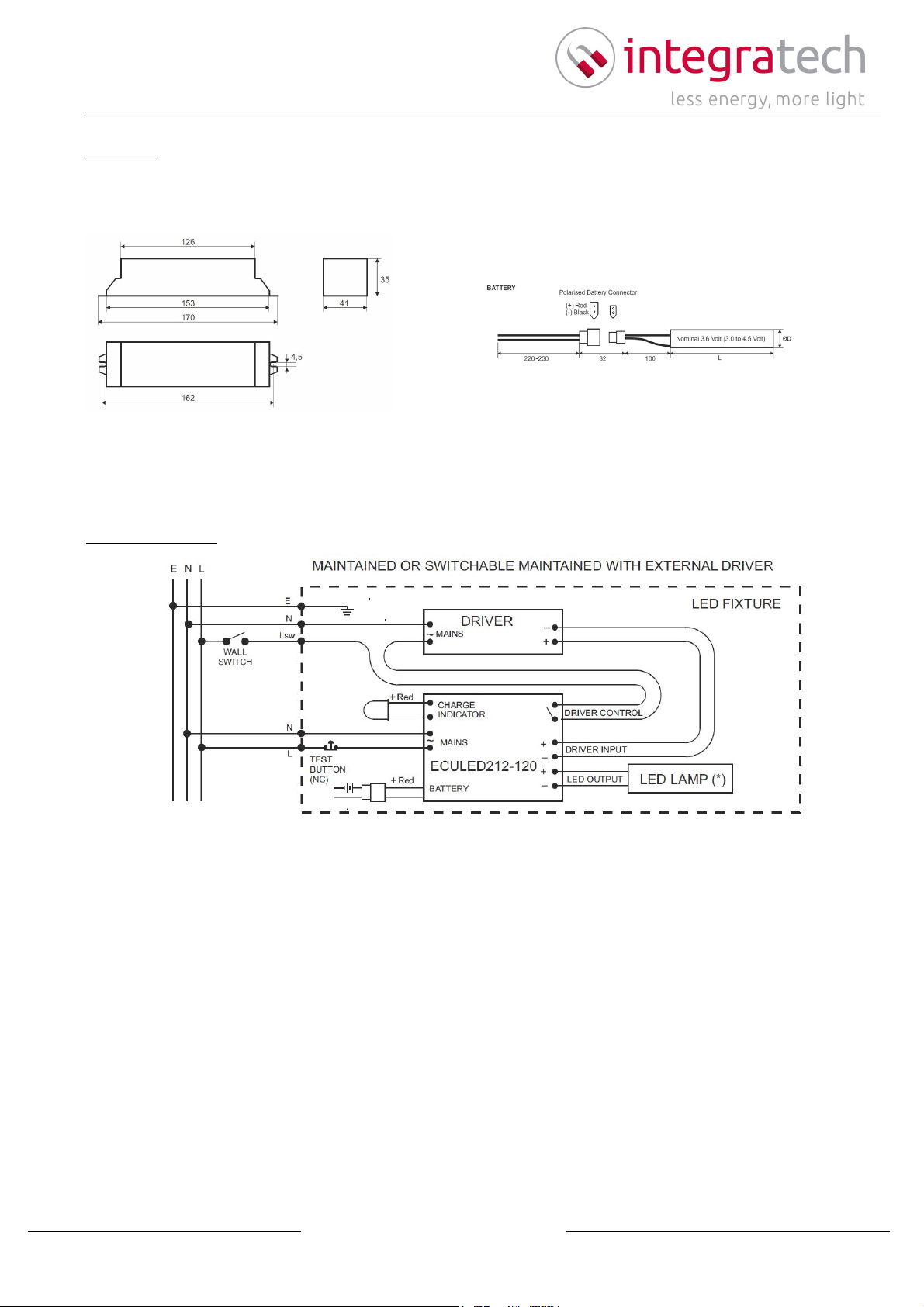
Dimensions (LxWxH) 170x41x35mm
Lifetime (h)
Flicker free yes
ENEC noETIM code EC000471
Technical specifications
Electrical specifications
Dimension and material properties
Warranty and certification
Number in bulk 12
Number on pallet
MOQ 1
Isolation class I
Stock item yes
www.integratech.be | +32 16 79 50 51
25/02/2020
Visit our website for all test reports LM-79 / LM-80 / TM-21 and elumdat files, subject to changes without notice.
Pagina 1 from 2
DATASHEET
ECULED212-1H
Connection diagram
Dimension
www.integratech.be | +32 16 79 50 51
25/02/2020
Visit our website for all test reports LM-79 / LM-80 / TM-21 and elumdat files, subject to changes without notice.
Pagina 2 from 2

MANUAL OF ECULED212 MODEL EMERGENCY LIGHTING CONVERSION KITS FOR LED LAMPS
WARNING! It is important that these instructions are read throughly before any installation work commences. They
must also be retained on file to provide information on use and maintenance by end-user. All installation work must
be carried out by a suitable qualified person and must comply with the instructions and all other relevant regulations.
Before any intervention to the unit, make sure that the mains voltage is disconnected.
INSTRUCTIONS
The environmental temperature and humidity conditions of the luminaire where the unit will be mounted in should be
suitable to the below indicated specifications. To achieve optimum performance, the unit and the battery pack should
be placed enough distant from the lamp and driver inside the luminaire and they should be kept at a max ambient
temperature below 50°C. The cable lengths are recommended max 100 cm. Do not make longer the battery cable.
First install the module and battery pack. Connect the LED lamp, driver and the charging indicator. Connect the
battery socket. Connect the mains.
WARNING ! The unswitched line and the switched line should be on the same phase. For the complete charge of
the battery, the unit should be left on charge for a minimum period of 24 hours.
OPERATING INSTRUCTIONS
The battery automatically charges through the unswitched line of the luminaire and the green charging indicator
LED lamp is lit. At that time the LED lamp could be turned ON/OFF through the wall switch connected to the driver
circuit driven by the switched line. When the mains goes out, the unit will automatically remove the power supply
of the switched line and energise the LED lamp (at the emergency lighting level) through the battery and not
depending on the wall switch position. When the mains is recovered, the luminaire will be energised by the
switched line through the wall switch and the battery will start the charge.
TEST INSTRUCTIONS
Function Test : This is a practical test to check shortly the function of the unit. While the test button is pressed the
luminaire will run at emergency mode. The Function Test has to be carried out once in a month by pressing the test
button or removing the mains line fuses.
Duration Test : The mains power of the luminaire has to be disconnected once at every 12 months and the
Duration Test has to be carried out to check battery backup duration. Before starting the Duration Test the unit
should be left on charge for a minimum period of 24 hours. If the backup does not extend to the declared duration,
the battery packs have to be replaced. The replaced batteries have to be returned to the manufacturer or to be
left at the special waste containers for recycling.
WARNING ! Do not dismantle any part of the unit, do not drill or bore. It does not contain any parts repairable by the
installer or user. Any of those kind of unauthorized interventions will cancel the warranty conditions.
TECHNICAL SPECIFICATIONS
Mains Supply
Battery
Lamp
Emergency Duration
Operating Mode
Charger
Charge Indicator
Battery Protection
Output Protection
Max Output Voltage
Terminals
Temperature
Class
Insulation
Humidity (RH%)
Protection Class
Construction
Standards
: 230 Volt, 50/60Hz, 0.02A max, 2.4VA max
: High Temperature type Ni-Cd Battery Pack with polarised connector,
nominal 3.6 Volt (3.0-4.5 Volt), 1.7Ah for 1 hour, 3.5Ah for 3 hours operation
: 1 to 12 serial connected Power LED (min 350mA/1W type)
: 1 or 3 hours
: Non-maintained, maintained or switchable maintained with external driver.
: Current controlled charger. The ballast is suitable for use only on battery supply
not having a trickle or intermittent re-charging circuits. The charger will charge
the battery normally after the test of EN 61347-2-7 Standard, Part 22.3.
: Ø5mm green LED lamp with panel type holder (55~60cm)
: Over charge & deep discharge protection. The ballast is not proof against supply
voltage polarity reversal but have a polarised battery connector.
: Open circuit, short circuit & overload protection
: Open Circuit Voltage 50 V DCMax Vout = 45V DC,
: 45º entry, quick fit terminal block for 0.2-0.75mm² cross section conductors
: Ambient Temperature ta: 0-45ºC, max Case Temperature tc: 90ºC
: Class II, no earth wiring required
: Basic insulation
: 20 - 90% RH
: IP20
: White polycarbonate (Flame rating UL94-V2)
: EN61347-1, EN61347-2-7
+
+
+
+
+
+
+
+
–
–
–
–
Red
Red
Red
Red
CHARGE
INDICATOR
CHARGE
INDICATOR
DRIVER INPUT
LED OUTPUT
LED OUTPUT
J
J
(*) Cut for longer duration or lower BLF.
(Refer to Table)
(*) Cut for longer duration or lower BLF.
(Refer to Table)
ECULED212
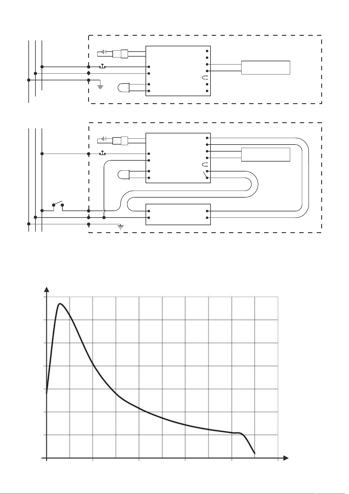
NON-MAINTAINED
MAINTAINED OR SWITCHABLE MAINTAINED WITH EXTERNAL DRIVER
ECULED212
DRIVER
LED LAMP (*)
LED LAMP (*)
MAINS
MAINS
BATTERY
BATTERY
~
~
~
L
L
N
N
E
E
LED FIXTURE
LED FIXTURE
WALL
SWITCH
TEST
BUTTON (NC)
TEST
BUTTON (NC)
Lsw
L
Line
L
N
N
Neutral
E
E
Earth
DRIVER CONTROL
WIRING DIAGRAMS
.
(*) LED LAMP : Serial connected Power LED(s) (refer to table)
Ballast Lumen Factor (BLF) = Emergency Ballast Lumen Factor (EBLF): It is a min ratio of the
emergency luminous flux of the LED LAMP supplied by ECULED212, to the luminous flux of the same
LED LAMP operated with the reference driver. Different LED LAMPS BLF could be find easly by related
LEDs "Relative Luminous Intensity / Forward Current" curve and the LED Current data. (refer below)
.
2/3
5 10 15 20 25 30 35 40 45
50
100
150
200
250
300
350
LED
VOLTAGE
(VOLT)
LED CURENT (mA)

153
126
170
162
4,5
Ø4
4
5x2mm hole for
cable tie wiring
mounting
screw M3
Battery
The battery pack could be mounted into the lighting fixture directly by cable ties or by mounting parts.
Battery
710
15
Ø7
41
L
35
ØD
10032
(when closed)
220~230
(from the outer side of housing)
(+) Red
(-) Black
MODULE
BATTERY
BATTERY MOUNTING PART
Nominal 3.6 Volt (3.0 to 4.5 Volt)
Polarised Battery Connector
SPECIFICATIONS
Battery Type
Temperature Rating
Dimensions
Charge Voltage Limits
Max Charge Current
Min Charge Current
Discharge Voltage Limits
Max Discharge Current
Min Discharge Current
ECULED212-1H (1 hour)
Ni-Cd, 3.6 Volt, 1.7Ah, SC size
High Temp type, T50 ºC
mm, L:130mmØD:23
3.0 - 4.5 Volt DC
135mA
45mA
3.0 - 4.5 Volt DC
875mA
18mA
ECULED212-3H (3 hours)
Ni-Cd, 3.6 Volt, 3.5Ah, C Size
High Temp type, T50 ºC
26mm, L:180mmØD:
3.0 - 4.5 Volt DC
280mA
85mA
3.0 - 4.5 Volt DC
875mA
18mA
DIMENSIONS (mm)
Table of contents


