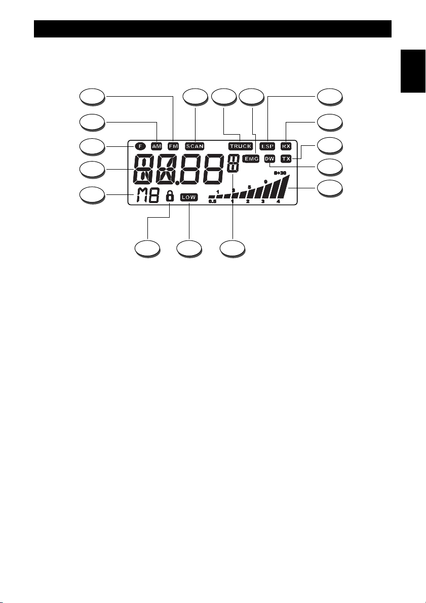
Controls and operation
- 5 -
English
again. Auto-scan may be also re-started at any time by pressing again the SCAN key. To exit the SCAN mode, shortly press the
PTT button (27). This key is also used to program and select the memory channel M2 (refer to item .11).
8. LCR and M3 Key
By pressing the LCR (Last Channel Recall) key, radio will automatically select the last used channel. This key is also
used to program and select the memory channel M3 (refer to item .11).
9. DW and M4 Key
The DW (Dual Watch) function allows automatic alternate monitoring of two programmable channels. Select the first
channel to be monitored using the channel selector knob (13) or the channel selection keys on the microphone (28, 30).
To enable the DW function, press the DW key for about 2 seconds, until the DW icon (I) appears and blinks on the LCD
display. Now select the second channel to monitor using the channel selector knob (13) or the channel selection keys on
the microphone (28, 30). Press again the DW key for about 2 seconds. The DW function is now enabled and the LCD
display will alternately show the channel number of the two programmed channels. The DW icon (I) will be lighted on the
LCD display. Monitoring stops if a signal is detected on one of the two channels, in order to let the user listen to the
incoming signal and will start again when no signal is detected on that channel. It is possible to transmit on that channel,
by simply pressing the PTT key (27). If there is no transmission within 5 seconds, monitoring will re-start. To exit the DW
mode, shortly press the PTT button (27). This key is also used to program and select the memory channel M4 (refer to
item .11).
10. TRUCK Key
The TRUCK key is an exclusive function of some INTEK mobile CB radios. This key allows programming and quick
access to a special memory channel, specifically devoted to truck drivers communications. To program the TRUCK
memory channel, select the desired channel using the channel selector knob (13) or the channel selection keys on the
microphone (28, 30). Then press and hold the TRUCK key until the TRUCK icon (D) appears on the LCD display. The
TRUCK channel is now stored in the special TRUCK memory and it can be immediately re-called by simply pressing the
TRUCK key.
11. F (Function) Key
The F (Function) key is used to enable various functions.
CHANNEL NUMBER READOUT OR FULL 5-DIGIT FREQUENCY READOUT
Press and hold the F key for about 2 seconds to read the programmed frequency band (first 2 digits) and the operating
channel number (next 2 digits) i.e. DE.40. Press and hold again the F key for about 2 seconds to change the reading
and read the full 5-digit operating frequency (in KHz), i.e. 27.405.
MEMORY CHANNELS (M1-M4) PROGRAMMING
Select the channel to be programmed and stored in one of the four available memories (M1-M4), using the channel
selector knob (13) or the channel selection keys on the microphone (28, 30). Shortly press the F key and the F icon (C)
will blink on the LCD display. Now press and hold one of the memory keys M1, M2, M3 or M4 for about 2 seconds, until
the memory channel number will appear on the LCD display (i.e. M1). All the specifications associated to each channel
will be stored in memory (i.e. AM/FM mode, EU/UK mode, transmitter power, etc.).
MEMORY CHANNELS (M1-M4) SELECTION
Shortly press the F key and the F icon (R) will blink on the LCD display. Now press one of the dual function keys (M1 to
M4) to quickly recall and access to one of the programmed memory channels. The selected memory channel number
will appear on the LCD display (P).
FREQUENCY BAND / COUNTRY CODE / OPERATING MODE PROGRAMMING
Please refer to the related section at page. 11.