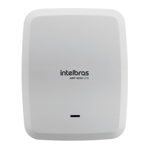
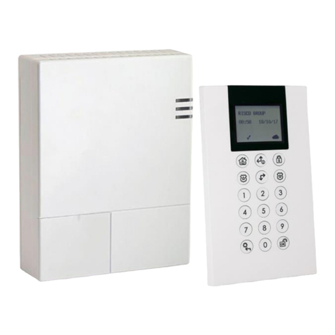
Intelbras 8000 Series User manual

User manual
AMT 8000 LITE
AMT 8000 PRO
English

AMT 8000 LITE and AMT 8000 PRO
Alarm center
Congratulations, you have just acquired a product with Intelbras quality and security.
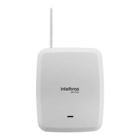
The wireless alarm centers AMT 8000 LITE and AMT 8000 PRO have advanced technology and are easy to program.
They can be connected to all series 8000 devices by exchanging encrypted information for greater system security.
Both models have an integrated siren and 16 partitions. The system features differentials such as high-performance
(bidirectional) wireless device communication with a range of up to 1000 meters without barriers and direct targeting,
GPRS, GSM, Ethernet/WI-FI and telephone line connections1to provide greater ease for monitoring reporting to 2 IPs
(monitoring companies), 2 telephone numbers (monitoring company) plus the Intelbras Cloud connection, initially using
the random remote access password indicated together on the QR Code label that also contains the MAC.
The alarm centers, AMT 8000 LITE and AMT 8000 PRO, have remote software (rmware) update, using Ethernet
communication for the execution of download the rmware version. In addition to this option, the alarm center can
also be updated by using the BootLoader feature. For this, it is necessary to have the Atualizador (Updater) 8000
software previously installed on your computer.
1
Phone line (FXO 8000 module card required) and Wi-Fi only for AMT 8000 PRO.
ATTENTION: this product comes with a factory default password. For your security, it is imperative
that you change it as soon as you install the product and ask your technician about the congured
passwords, which users have access and the recovery methods.

Care and safety
» Follow all instructions in the manual for installation and handling of the product.
» Carry out the installation in environments that are not susceptible to factors such as rain, fog and water splashes.
» Wireless communication technology, when exposed to environments with high power radiation, may suffer interference
and have its performance impaired. Example: locations nearTV towers,AM/FM radio stations, amateur radio stations, etc.
» Do not install the alarm center and its accessories near radio frequency equipment such as routers, repeaters and/or Wi-Fi
signal ampliers. The alarm center and its devices must maintain a minimum distance of 2 meters from these equipment.
» Do not install the alarm center facing air conditioning or heating equipment.
» Do not expose directly to sunlight.
» Only clean the external part of the device, using only a damp cloth (do not use chemical solvents).
» Do not subject the device to excessive pressures or knocks/drops.
» Check whether the installation site, the indicator LED of the devices ashes green when activated.
» Avoid installation on metallic surfaces so as not to attenuate the transmission signal between system devices.
» The installation and conguration of the alarm center and the other products that make up this system must be carried
out by a qualied professional.
» Perform periodic tests on it, in order to validate weather conditions, battery level and other factors, so that the site
monitored by the system is always able to operate correctly.
» LGPD - General (Personal) Data Protection Regulation: Intelbras does not access, transfer, capture, or carry out any other
type of personal data processing from this product.

Summary
1. Technical specications 6
2. Features of the alarm centers, AMT 8000 LITE and AMT 8000 PRO 7
3. AMT 8000 LITE and AMT 8000 PRO Accessories 7
3.1. GPRS module XG 2G, GSM XG 3G and GSM XG 4G .................................................7
3.2. Communication module via telephone line – FXO 8000 ..............................................8
4. Installation of the alarm center and its peripheral devices 9
4.1. Alarm center power supply (full range 90 and 265 Vac) .............................................11
4.2. Battery. . . . . . . . . . . . . . . . . . . . . . . . . . . . . . . . . . . . . . . . . . . . . . . . . . . . . . . . . . . . . . . . . . . . . . . . . . . . . . . . . .11
4.3. XG 2G/XG 3G/XG 4G module ................................................................12
4.4. FXO 8000 Phone Module....................................................................12
4.5. AMT 8000 LITE and AMT 8000 PRO alarm center..................................................13
5. Operation 13
5.1. Description of XAT 8000 LCD keyboard indications.................................................13
5.2. Exhibition of problems ......................................................................13
5.3. Description of the LED signaling on the alarm center boards..........................................13
5.4. Partitioning ..............................................................................14
5.5. Alarm center activation/deactivation............................................................14
5.6. Menu. . . . . . . . . . . . . . . . . . . . . . . . . . . . . . . . . . . . . . . . . . . . . . . . . . . . . . . . . . . . . . . . . . . . . . . . . . . . . . . . . . .16
5.7. Remote update ...........................................................................19
6. Programming 19
6.1. Wi-Fi Provisioning .........................................................................19
6.2. Connection to the AMT 8000 PRO Wi-Fi network ..................................................19
6.3. Programming mode .......................................................................20
6.4. Wireless devices (register/delete) ..............................................................22
6.5. Wireless sensor functions ....................................................................27
6.6. Remote control key functions .................................................................29
6.7. Wireless keyboard functions ..................................................................31
6.8. Siren functions............................................................................33
6.9. Update .................................................................................40
6.10. Passwords ..............................................................................40
6.11. Quick congurations for monitoring ...........................................................44
6.12. Congurations of zones ....................................................................48
6.13. Program the partitioning of the alarm center ....................................................51
6.14. Timings ................................................................................52
6.15. Alarm center time congurations .............................................................54
6.16. Time zone ..............................................................................56
6.17. Periodic test.............................................................................57
6.18. Automatic activation ......................................................................57
6.19. Monitoring congurations ..................................................................61
6.20. Activation/deactivation of functions ...........................................................79
6.21. Time for sending of AC failure................................................................82

6.22. System reset ............................................................................83
6.23. Programming quick reference................................................................83
6.24. Approval ..............................................................................101
Warranty Terms 102

6
1. Technical specications
Product Monitored alarm center
Communication AMT 8000 LITE Ethernet
AMT 8000 PRO Ethernet/Wi-Fi
WI-FI Provisioning AMT 8000 PRO
Integrated siren Audible power of 100 decibels at 1 (one) meter
AC Power Supply 90 to 265 V (it is recommended to use a cable with gauge ≥1 mm)
DC Power Supply 5.7 coming from the AMT 8000 LITE/PRO source
Battery 3.7 Vdc rechargeable battery (comes with the alarm center)
Operating temperature –10 °C to 50 °C @ 90% humidity
Weight 568 grams (with battery)
Dimensions (W × H × D) About the product: 84 × 290 × 273 mm
With individual packaging: 90 × 292 × 276 mm
Average power¹
AMT 8000 LITE: 5.2 Watts
AMT 8000 LITE + XG: 8.1 Watts
Antenna type: indoor
Antenna gain: 0 dBi
Wireless communication frequency
AMT 8000 LITE/PRO/Accessory 915 to 928 MHz via internal antenna, power 18 dBm
Modulation DSSS BPSK 40 Kbps
Battery AMT 8000 LITE internal 3.7 Vdc 2 A rechargeable lithium
AMT 8000 PRO internal 3.7 Vdc 3 A rechargeable lithium
Optional devices²
XAC 8000 remote control
REP 8000 Range RF Amplier
XAT 8000 Wireless Keyboard
XAS 8000 wireless magnetic sensor
Universal Transmitter TX 8000
IVP 8000 EX wireless passive infrared sensor
IVP 8000 Pet Wireless Passive Infrared Sensor
Wireless passive infrared sensor IVP 8000 Pet Cam
GPRS XG 2G Module
GSM XG 3G Module
GSM XG 4G Module
FXO 8000 module
XSS 8000 Wireless Siren
PGM 8000 wireless actuator
1
Conditions: maximum power veried with the alarm control panel activated, with registered peripherals (keyboards/sensors/sirens) and with
the means of communication connected and operating together with the alarm center. In some operations, consumption may vary according to
the number of peripherals operating in the security system and their exchange of information (
Stand by
mode - continuous).
² Optional devices: FXO 8000 module compatible only with the AMT 8000 PRO model, for more information, consult the website
www.intelbras.
com.br.
Attention: Intelbras wireless systems are tested with the highest standards of demand and bring high reliability, however,
due to the use/installation in varied scenarios, some considerations must be taken into account:
» Transmitters/receivers may be disturbed by radio signals, natural interference, location of device operation, weather
issues and other adversities that affect data transmission regardless of the frequency or technology used, since the
transmission medium is adverse and different from place to place.
» Device receivers/transmitters have an internal processing time, and only receive the necessary data for communication
between them after this particular time for the system.
» Wireless devices should be tested regularly to determine if there are any sources of interference and to protect against
occasional failures.

7
2. Features of the alarm centers, AMT 8000 LITE and AMT
8000 PRO
» Capacity for 16 partitions with independent activation/deactivation.
» Allocation of zones according to the desired partitions.
» Wireless signal receiver/transmitter integrated into the alarm center operating at a frequency of 915 to 928 Mhz.
» Support 2 SIM card mobile phone with XG 2G, XG 3G or XG 4G module installed.
» Quad band GPRS modem: compatible with most national GSM operators for AMT 8000 LITE and AMT 8000 PRO oper-
ating with XG 2G, XG 3G and XG 4G module (sold separately).
» Event reporting:
» AMT 8000 LITE: event reporting via Ethernet connection, GPRS connection (with XG 2G module installed - sold
separately), GSM connection (with XG 3G module installed - sold separately) and GSM connection (with XG 4G
module installed - sold separately).
» AMT 8000 PRO: event reporting via Ethernet/Wi-Fi connection, via telephone line (with FXO 8000 module installed
- sold separately), GPRS connection (with XG 2G module installed - sold separately), GSM connection (with module
XG 3G installed - sold separately) and GSM connection (with XG 4G module installed - sold separately).
» Remote access to the alarm center via application.
» Use in conjunction with all wireless devices in the 8000 line.
» Capacity for visualization and programming of parameters by up to 16 XAT 8000 keyboards.
» Built-in wired siren plus 16 XSS 8000 wireless sirens.
» Capable of connecting up to 98 XAC 8000 controllers with user identication.
» Capacity for connecting up to 64 wireless sensors from the 8000 line.
» Remote programming via Ethernet, GPRS and GSM.
» Capacity for connecting up to 04 REP 8000 RF ampliers. Programming for up to 97 passwords including duress with
congurable permissions.
» Monitorable by Contact-ID protocol.
» Supervision of sensors, wireless sirens, keypads, PGMs and repeaters.
» Low battery detection of wireless devices.
» Internal buffer for 512 events.
» Remote software update via Ethernet connection.
3. AMT 8000 LITE and AMT 8000 PRO Accessories
The AMT 8000 LITE and AMT 8000 PRO alarm centers can have various accessories grouped together to compose the monitor-
ing and security system, with the accessories responsible for communication and monitoring, the sound warning, LCD keyboard
and various sensors, for better adequacy and composition of the necessary protection system.
3.1. GPRS module XG 2G, GSM XG 3G and GSM XG 4G
Optional dedicated accessory for data transmission via GPRS / GSM for communication, conguration and event reporting
between user and/or monitoring company with the AMT 8000 LITE and AMT 8000 PRO security system.
Features
» It supports up to two SIM card type chips.
» 2G GPRS communication with XG 2G module, 2G/3G communication with XG 3G module and 4G communication with
XG 4G module.
» External antenna with 0 dBi gain.
» Reports events to 2 IP destinations (monitoring company) plus the Intelbras cloud.
» Connections with DNS destinations.
» Power supply from the AMT 8000 LITE or AMT 8000 PRO alarm center.

8
The following gure presents an illustrative image of the XG 2G, XG 3G and XG 4G modules:
ST
100
25V
GPRS module XG 2G, GSM XG 3G and GSM XG 4G
Obs.: XG 2G, XG 3G and XG 4G modules are compatible with most national GPRS / GSM operators with 2G, 3G and 4G
technology.
3.2. Communication module via telephone line – FXO 8000
Dedicated optional accessory for data transmission via telephone line for communication and event reporting to the monitor-
ing company with the AMT 8000 security system, in addition to dialing up to 5 personal telephones and issuing, through the
telephone line, the sound of a siren.
Attention: the FXO 8000 module is only compatible with the AMT 8000 PRO alarm center.
Features
» Up to 7 programmable phone addresses.
» DTMF type dialing mode.
» Telephone line cut/interruption check.
» Contact-ID communication protocol.
» Power supply from the AMT 8000 alarm center.
The following gure shows an illustrative image of the FXO 8000 module:
+
10
50G
682
FX8000
4640353/P/4P
108XXXX
LINHA FONE
FXO 8000 Phone Line Module

9
4. Installation of the alarm center and its peripheral devices
Attention: only connect the central to the mains and battery after installing all the equipment and peripheral devices.
Open the product box and then open the alarm center cabinet cover by removing the screws, where you will be able to see
two plates, that is, its basic conguration contains the AMT 8000 LITE or AMT 8000 PRO alarm center plate and its respective
power supply and the rechargeable battery that comes with the alarm center.
You can purchase the XG 2G, XG 3G and XG 4G modules for the AMT 8000 LITE alarm center and the XG 2G, XG 3G, XG 4G
and FXO 8000 modules for the AMT 8000 PRO, and these boards have their respective interconnection cables with the alarm
center.
The AMT 8000 LITE and AMT 8000 PRO alarm center have only wireless zones, as well as other accessories (keyboard, sirens,
etc.) are connected to the alarm center via a wireless signal, with only the AC power and Ethernet cables connected to alarm
center.
The following image illustrates the alarm center with all the devices that can be physically connected:
13
123
5
6
7
8
12 11 10 9
4
AMT 8000 LITE/PRO alarm control
1. Opening for passing the Ethernet cable and telephone line (AMT 8000 PRO compatibility).
2. Integrated siren connection.
3. Connector for Ethernet network cable.
4. WI-FI Module (AMT 8000 PRO compatibility).
5. Button for registering wireless devices.
6. Connector for power supply at cable.
7. Micro-USB type connector for updating the alarm control panel’s rmware.
8. Connector for FXO 8000 module at cable (AMT 8000 PRO compatibility).
9. Connector for at cable of XG 2G, XG 3G and XG 4G modules.
10. Connector for connecting the telephone line and telephone (AMT 8000 PRO compatibility).
11. FXO 8000 board ground point (AMT 8000 PRO compatibility).
12. Connector for SIM 1 and SIM 2 card.
13. Input connector for battery connection.
Note:
XG 2G, XG 3G and XG 4G modules are compatible with most national GSM operators with 2G, 3G and 4G
technology.

10
1
3
2
AC AC
1. Tamper-proof switch.
2. Integrated siren.
3. Connector for AC power.
Caution: be careful not to invert the position of the ground wire.
Attention: the AMT 8000 LITE and AMT 8000 PRO alarm control panels do not have an auxiliary output to power
other devices and no connection point on the control panel boards (control panel or source) should be used for this
functionality, as in addition to damaging the alarm control panel and its accessories, it may damage the devices that
are connected because the alarm panels operate with different voltages.

11
4.1. Alarm center power supply (full range 90 and 265 Vac)
The alarm center is equipped with a full range switching power supply that works with input voltages of 90 and 265 Vac
without the need for a voltage selector switch. In this way, even if there is some voltage variation in the electrical network, the
alarm center will continue to function normally (as long as the voltage is in the range of 90 to 265 Vac).
There are two alarm center protection fuses on this board. If you need to change it, use new ones of the same value (250
V/400 mA).
To connect the AC electrical grid input and also to ground, it is recommended to use a three-pin cable with a gauge of 1 mm
or greater.
The output for the alarm center board is 5.7 Vdc and 1.7 A.
AC AC
AMT 8000 LITE/PRO power supply
Connect the ground terminal of the source as shown in the image above to the ground of the local electrical installation.
If the local electrical installation does not have grounding, install a grounding bar and connect the connection terminal to the
alarm center to carry out the correct grounding.
Attention: it is mandatory that the grounding connection be done on the alarm center so that there is greater protection
against lightning and overload by the electrical grid. If this connection is not made, the alarm center will work normally, but it
will be unprotected against overloads
The warranty does not cover possible damage caused by lightning to the alarm center or any other equipment connected to it.
4.2. Battery
The AMT 8000 LITE alarm center has an internal rechargeable battery of 3.7 Vdc and a capacity of 2,000 mA and the AMT
8000 PRO alarm center has an internal rechargeable battery of 3.7 Vdc and a capacity of 3,000 mA. The battery connector
is located on the power supply board and is used to connect the battery in the alarm system. To turn on the battery in this
connector, use the cable that comes with it, as shown in the gure below.
AC AC
Rechargeable battery for AMT 8000 LITE and AMT 8000 PRO alarm center

12
The alarm centers have protection against inversion of polarity and short circuit in the battery and protection to prevent the
battery from being damaged in the event of a failure in the electrical grid (if the battery voltage is below 2.8 V, the control unit
will turn off so as not to damage the battery).
Attention: the battery can take up to 12 hours to complete its rst charge cycle.
Battery duration:
» Approximately 4 hours reporting events via GPRS/Ethernet + built-in siren on constant re;
» Approximately 13 hours reporting events via GPRS (only hourly periodic test and with integrated siren in stand by);
» Approximately 17 hours reporting events via ETH (only hourly periodic test and with integrated siren in stand by).
Attention: if it is necessary to replace the battery, contact our accredited technical assistance network.
4.3. XG 2G/XG 3G/XG 4G module
In the modules XG 2G, XG 3G and XG 4G there are two slots to be allocated two chips (SIM card) overlapping one over the
other, with chip 1 being above chip 2. When installing the chips, leave their metallic contacts facing downwards and insert
them to the end of the slot for the correct allocation of the chips.
2
1
CHIP
CHIP 1CHIP 2
Chip allocation on the module
4.4. FXO 8000 Phone Module
Check if the cable for connection to the alarm center is correctly connected, and its installation should only be done with the
alarm center turned off to avoid damage to the equipment and the installer.
In the FXO 8000 module there is a Line terminal, where it must be connected to the main telephone line (two wires), con-
necting the Phone output (two wires) to the other telephone devices contained in this same line and as can be seen in the
following image:
Line
Phone
Telephone line connection plan on the FXO 8000 module
Attention: the FXO 8000 module is only compatible with the AMT 8000 PRO alarm center.
This connection is necessary so that, in the case of reporting events or remote accesses, the alarm center does not run out of
communication or have it interrupted if other telephones on the same circuit start/are in operation. In this case, at the time of
event reporting, the other phones will be inoperative, as the alarm center will be occupying the line.

13
4.5. AMT 8000 LITE and AMT 8000 PRO alarm center
The AMT 8000 LITE and AMT 8000 PRO alarm centers have an integrated wired siren, tamper switch against violation, and
if the tamper switch is opened/violated, the integrated siren plus the registered sirens will go off and send the corresponding
event if the function Problems that generate trigger is enabled (see section
Problems that generate trigger
).
Ethernet and AC power supply cables must be routed through the hole located on the back of the alarm center.
The installation of the alarm centers can be on different surfaces, always placing them in a vertical position with a height
between 1.80 and 2.20 meters and using double-sided tape or screws (not included) to x the base and after attaching the
alarm center, tting and checking that there was correct placement so that there are no falls and damage and directing the
wires in the dedicated areas.
5. Operation
Once the installation is complete, turn on the control unit by connecting it to the local electrical grid and to the rechargeable
battery.
Obs.: to turn on the AMT 8000 LITE and AMT 8000 PRO alarm centers, it is necessary that they are connected to the AC
network, otherwise the alarm centers will not turn on, even if the batteries are connected. In the event of an AC power outage,
the alarm centers will be maintained by the battery and when the AC network returns, the batteries will be recharged.
5.1. Description of XAT 8000 LCD keyboard indications
At the top of the LCD display are located the indication icons described below:
» :if this icon is ashing, it indicates that a problem has been detected.
» :will light whenever there is trigger in the siren
.
» P: with the icon accessed, the alarm center is in programming mode.
» Battery: indicates the battery status of the alarm center.
5.2. Exhibition of problems
The occurrence of problems is described as follows:
On the XAT 8000 keyboard, the icon will be blinking.
If any problems are detected, press the up or down arrow keys on the XAT 8000 keyboard to view them. To end the display,
press the
Exit
key.
Obs.:
»
If the function Indication of problems by siren on activation/deactivation and Siren beep on activation/deactivation are
enabled and if a problem is detected, 1 long beep will be emitted on activation and 2 long beeps on deactivation.
»
To clear the keyboard after shots, just press the
Exit key.
5.3. Description of the LED signaling on the alarm center boards
alarm center base plate LEDs
LED Status/event Signaling1
LED1/LED2 Disconnected from the Ethernet network LED off
LED1/LED2 Connected with the Ethernet network1LED blinking constantly
LED3 Alarm center off LED off
LED3 Alarm center on LED blinking
LED3 Alarm center on and registering devices LED accessed
1
This status does not mean that the system is connected to the monitoring servers. To view the connection status, observe through the
Menu
function (see section
Connections
).

14
GPRS XG 2G/ XG 3G board LEDs
LED Status/event Signaling1
LED1, LED2 Power supplied (on on the CPU board) LED1 and LED 2 constantly accessed
LED1, LED2 Chip (SIM1 or SIM2) looking for
connection Only the corresponding accessed LED
LED1 Chip 1 (SIM1) connected to servers LED blinking once (connected to server 1),
LED blinking twice (connected to server 2)
LED2 Chip 2 (SIM2) connected to servers LED blinking once (connected to server 1),
LED blinking twice (connected to server 2)
1
This status does not mean that the system is connected to the monitoring servers. To view the connection status, observe through the
Menu
function (see section
Connections
).
5.4. Partitioning
Using this feature through the control panel's programming, it is possible to divide it into up to 16 partitions with independent
activation and deactivation and associate any of the 64 wireless zones to any of the partitions. It is also allowed to program
passwords giving specic permissions for these partitions.
This function is useful in ofces, homes or other places in the same building that need more alarm panels, because with parti-
tioning, the panel is divided and each partition operates individually, as if it were an independent alarm center.
The 16 partitions can be controlled via keyboard, remote control, software and applications compatible with the AMT 8000
LITE and AMT 8000 PRO alarm centers, as one partition can be activated or deactivated without inuencing the other.
When the system is partitioned, zones and any of the other wireless devices on the 8000 Line can be partitioned as shown
below (for more information, see section
6.10. Conguration of zones
).
» Common: The zone does not belong to any of the partitions. It will only be activated when all partitions are activated
and will be deactivated whenever one of the sixteen partitions is deactivated.
Example: in an ofce divided by two professionals, one room is dened for Partition 01, and another for Partition 02 and
the reception as the common zone. That way, even if one of the people leaves and activates his partition, the reception
will remain deactivated and will only be activated when the other partition is also activated.
» Partition (01 to 16): wireless devices registered in zones dened to belong to any of the 16 partitions will have access
or be inuenced by the chosen partition.
Example: in a gallery comprising 8 rooms, each room will have its own independent partition with specic zones, with
independent activation and deactivation. In this scenario, each partition can have independent sirens and keyboards or
share devices between partitions (common sirens and keyboards).
» Partial: zones selected for this option remain inactive during Partial
mode
wakeup regardless of the partition associated
with it.
Example: assuming that for partition 01, consisting of zones 01 to 10, only zones 01 to 05 are enabled as
Partial
mode.
When executing the command for the
Partial
mode option for a given partition, in this case, partition 01, if someone
passes in the sector where sensors 01 to 05 are located, the control panel will not trigger - zones where the occupants
of the place will be present and during activation of
Partial
mode do not trigger, since if someone passes through sensors
06 to 10, the control panel will trigger for partition 01, indicating such triggered sectors, being signaled by sirens and
sending events to monitoring/applications, if used.
Obs.: during full partition activation - outside of Partial mode, all zones in the partition will trigger.
5.5. Alarm center activation/deactivation
The alarm center can be activated and/or deactivated in different ways, depending on the dened settings. For any of the ways
to activate the system, with the exit time different from zero, after entering the password, the keyboard will emit beeps at
intervals of 1 second. In the last ve seconds of the delay, these beeps will become faster to indicate that the exit delay is at
an end. At the end of the exit time, the siren will emit a sound (if programmed) indicating that the alarm center is activated.
Attention: » For some programming of the alarm center and also to activate it, it is necessary to use the 4-digit master
password, indicated on the QR code label inside the alarm center. This password can be changed as discussed
in the elds below.
» If the switchboard system is reset, it will no longer use the random passwords that are linked together with the
QR code label pasted inside the switchboard and will use password
1234
as the master password and password
878787
as access remote until they are changed again.

15
Obs.: » If there is a mistake in entering the password, press the
Back
key and enter the password again.
»
When the control panel or partition receives the command to activate and any of the zones is open, a fault/error will
be generated (long beep on keypads) and it will only be possible to activate the control panel when all zones are
closed in the case of a complete or non-partitioned system , or in the case of partitioned systems with the zones of the
respective partitions closed. To activate the control panel with open zones, see section
General Settings 1
.
Activation / deactivation in non-partitioned systems
Full
mode activation
To fully activate the system, enter a valid password on the XAT 8000 keyboard, for example the master password.To nd out if
the alarm center is activated, just slide the keyboard cover and view the message, if the alarm center is activated, the message
will be shown:
Alarm activated
, otherwise
Alarm deactivated
will be shown.
Activation through a key
If the
One-Key Activation
function is enabled (see section
General Settings 1
), pressing and holding the active key until the
keypad emits a conrmation beep ( + /- 3 seconds) will activate the system in
Full
mode. The exit timing will be started in order
to leave the protected area.At the end of the exit delay, the system will be activated in
Full
mode (all partitions).This procedure
does not allow to deactivate the system.
Obs.: if a common keyboard is used, all partitions will be activated in the case of a partitioned alarm center. In case of
keyboard with permissions for partitions, only the partition where this keyboard has permission will be activated.
System deactivation
To deactivate the system enter a valid password, for example the master password. After entering the password, the control
panel will be completely deactivated and the
Deactivated alarm
information will be displayed.
Zones, which must be passed through to reach the keyboard, must be programmed as timed for entry or as followers so the
alarm does not go off immediately when the keyboard access path is breached/accessed. After entering the area protected by
a timed zone for entry, the entry timing will start and the user must enter a valid password on the keyboard before the delay
expires, to avoid triggering the alarm and reporting the corresponding events. See section
Zone functions
to dene as timed.
Activation/deactivation by remote control
To activate/deactivate the system by remote control, it is necessary that it is registered in the control panel, as described in
section
6.2 Wireless devices (registration/delete).
The control leaves the factory congured so that button 1 only deactivates the alarm center, button 2 only activates it and
button 3 is disabled. The remote control will have the same permissions as the password of the user it is associated with (user
00 to 97).
Activation / deactivation on partitioned systems
Before trying to carry out the following operations, it is necessary to program the alarm center for one of these conditions and
to do so, consult the section
6. Program.
Activation by master password or full password
If you are using the master password or a full password (which has permission to activate/deactivate more than one partition),
there are two ways of activation:
» All partitions: enter the password, the exit timing will start and at the end, all partitions will be activated.
» Desired partition only: press the
Activate key + Partition (01 to 16) + Password.
The exit timing will start and at the
end, the partition chosen in the range (01 to 16) will be activated.
With the partitioned alarm, when entering the MASTER password, if there is any activated partition, it will deactivate the
activated partitions and will not activate the pending partitions.
Activation in Partial mode
Activation in
Partial
mode allows you to partially activate the system, that is, it is possible to select some zones to remain
deactivated while others remain activated. For example, it is possible to activate the external zones while the internal zones
remain deactivated, allowing people to circulate inside the property without triggering the alarm. But, if someone tries to break
into the place through an activated zone, the alarm will go off normally.
In this mode, the zones selected for
Parcial
mode remain disabled and the other zones will be activated normally.
To activate
Parcial
mode, enter
Partial + Password
. The exit timing will begin and the keyboard will beep at 1 second intervals.
In the last 5 seconds of the timing, these beeps will become faster to indicate that the exit time is at an end. To activate, in
Partial
mode, a specic partition with a password with permission for more than one partition, use the sequence
Activate +
Partial + Partition (01 to 16) + Password
.

16
Obs.: only master password and passwords with permission to enable
Partial
mode enabled can activate the system in
Partial
mode.
Deactivation by master password or full password
If you are using the master password or a full password (which has permission to activate/deactivate all partitions), there are
two forms of deactivation:
» All partitions: type the password and all partitions will be disabled.
» Desired partition only: press
Deactivate key + Partition (01 to 16) + Password
and the chosen partition in the range
(01 to 16) will be deactivated.
Zones, which must be passed through to reach the keyboard, must be programmed as timed for entry or as followers so the
alarm does not go off immediately when the keyboard access path is breached/accessed. After entering the area protected by
a timed zone for entry, the entry timing will start and the user must enter a valid password on the keyboard before the delay
expires, to avoid triggering the alarm and reporting the corresponding events. See section
Zone functions
to dene as timed.
Activation/deactivation by specic user password
Specic passwords can be programmed to activate/deactivate a Partition (between 01 to 16). In this case, just enter the pass-
word to activate/deactivate the corresponding partition.
Upon activation, the exit timing will start and the partition will be active at the end of the programmed time.
Upon deactivation, the keyboard must be accessed through a timed zone if necessary and the password entered before the end
of the programmed time so that there is no triggering and event reporting.
Activation/deactivation by remote control
To activate/deactivate the system by remote control, it is necessary that it is registered in the alarm center, as described in
section
6.2 Wireless devices (registration/delete).
The control leaves the factory congured so that button 1 only deactivates the alarm center, button 2 only activates it and
button 3 is disabled. The remote control will have the same permissions as the password of the user it is associated with (user
00 to 97).
5.6. Menu
The alarm center has the
Menu
function to facilitate the visualization of the status and the execution of some commands.
When accessing one of the options, if you want to return to the
Main
menu, press the
Back
or
Exit
key to direct you to the
initial screen.
Bypass
Through this function it is possible to temporarily cancel one or more zones. With this function, zones that are bypassed (suffer
bypass) during the next activation will not generate triggers in the system if they are violated.
After the system is deactivated, zones that were bypassed will revert to their normal conguration. Only the master password
user and users with bypass permission can temporarily cancel a zone.
This function must be programmed at most 30 seconds before the system is activated, otherwise the operation will be canceled.
The procedure for temporarily canceling a zone is as follows:
1. With the system off and out of programming mode, press the
Menu
key;
2. With the marker in the bypass position, press the
Enter key;
3. Through the numeric and directional keys on the keyboard, select which zones will have the bypass active (01 to 64);
4. Press the
Enter
key to conrm the cancellation of the selected zones;
5. Type in the master password or a password with permission to cancel zones;
6. If an invalid password is entered, the message
Incorrect password error
will be displayed and the keypad will continue to
display the zones to be canceled until a valid password is entered or it exceeds the time of 30 seconds. If a password is
entered without permission to cancel, the message
No permission to cancel sensor
will be displayed and the operation
will be canceled immediately;
7. To cancel the operation, press the
Exit
key before entering the password.
To cancel a zone more than 30 seconds before activation, enter in the programming mode (
Enter + Password
) using a pas-
sword with permission for bypass and perform steps 1 through 4. The next time the system is activated, the bypass will be
performed, even if the user who performed the activation does not have permission to bypass.
synchronization

17
Open sensors
In normal operation mode, the XAT 8000 keyboard will display the status of the alarm center and if there are any open zones.
To view currently open zones, press the
Menu
key and then access
Open sensors
and press the
Enter key.
Outside the programming mode, if
1 + Enter
is pressed, zones 1 to 10 will be displayed. 2 + Enter displays zones 11 through
20, and so on, up to the key 7, which displays zones 61 through 64.
The status of the sensors in their respective zones will be displayed, distributed in divisions of 10 zones. To change the group
of zones press the arrow keys down or up, for example to access zones 41 to 50 press the down key on the keyboard until
the number 4 appears in front of the rst square, making the number 1 referring to zone 41 and so on, making the number
5 referring to zone 50.
Group 1 will represent zones 1-10, group 2 zones 11-20, and so on, up to zones in group 7, thus demonstrating the status
of zones 1-64.
To facilitate the interpretation of this way of identifying the status of the zones (open or closed), next to the number of the
sensor, a square will be displayed, which according to its marking will be the status of the zone:
» Empty square ( ) closed/unviolated zone.
» Filled square ( ) open/violated zone.
Trigger sensors
When the alarm center is active, sensors that are violated (disregarding canceled-bypass sensors) will generate triggers and
report events, and the display screen will show the information of the trips that alternate with the information of the status of
the alarm center (alarm activated or alarm deactivated).
When pressing
Menu
, with the directional keys leave the marker on
Trigger sensor
and press
Enter
key.Through the directional
keys navigate between the sensors/zones of the alarm center to check which sensors generated the trigger.
» Empty square ( ) closed/unviolated zone.
» Filled square ( ) open/violated zone.
Partitions
The partitions enabled on the control panel will be displayed (see the section
6.11. Program the partitioning of the alarm center
and its respective status.
When pressing
Menu
, with the directional keys leave the marker on
Partitions
and press
Enter
key.Through the directional keys
navigate between the partitions of the alarm center to check their status.
» Activated: The partition is activated.
» Deactivated: The partition is deactivated.
Connections
The status of connections for reporting events via IP to monitoring services will be shown.
In the
Cloud
menu of the keyboard, the alarm centers will have only one option lled in, that is, ETH or GPRS. However, priority
will be given to communication via ETH.
When pressing
Menu
, with the directional keys leave the marker on
Connections
and press
Enter
key.
» WI-FI: empty square ( ): not connected to the destination / lled square ( ): connected to the destination.
» Eth: empty square ( ): not connected to the destination / lled square ( ): connected to the destination.
» 2G/3G: empty square ( ): not connected to the destination / lled square ( ): connected to the destination.
Eth: IP1
2G/3G/4G: IP1
IP2
IP2
Status viewing function of IP1/IP2 connections. In this example, IP1 is connected via Ethernet network cable
Obs.:
»
XG 2G module covers 2G technology only, XG 3G module covers both 2G and 3G technology, and XG 4G module
covers both 2G and 4G technology.When the XG 3G or XG 4G module is used, the communication technology chosen
will depend on the availability of signal coverage by the operator in the region where the exchange is located.
»
Wi-Fi connection available only for the AMT 8000 PRO model.

18
See the section
Connections
to dene addresses of priorities and routings.
» Cloud: will display if the alarm center is connected to the Intelbras Cloud server via ETHERNET or 2G/3G/4G. This server
allows communication between the alarm centers and the remote access via application.
» Eth: empty square ( ): not connected to Intelbras Cloud / lled square ( ): connected to Intelbras Cloud.
» 2G/3G/4G: empty square ( ): not connected to Intelbras Cloud / lled square ( ): connected to Intelbras Cloud.
2G/3G/4G
It will display the operator's signal level in percentage, where square 1 represents a level less than or equal to 10% and square
0 represents 100%. The lled mark corresponds to the active signal and the empty mark to no signal, referring to the level in
10 divisions.
When pressing
Menu
, with the directional keys leave the marker on
2G/3G/4G Signal
and press
Enter
key.
1 2 3 4 5 6 7 8 9 0
Illustration of GSM network signal level function
Obs.: when the GPRS / GSM function is disabled, disregard this function.
Wireless signal
It will display the signal level in percentage of the wireless devices registered in the alarm center.
When pressing
Menu
, with the directional keys leave the marker on
Wireless signal
and press
Enter
key.
The signal level will be displayed on the keyboard, compared to the color of the LED indicator of the registered devices, as
below:
» Orange color: signal level between 1 and 2
» Green color: signal level between 5 and 10
Wireless signal can be viewed from the following devices:
» Sensors: devices registered in the alarm center at addresses 01 to 64. To visualize the signal of the sensors with the
marker on it, press
Enter
and then, with the directional keys, toggle between the sensors.
» Keyboards: devices registered in the alarm center at addresses 01 to 16. To visualize the signal of the keyboards with
the marker on it, press
Enter
and then, with the directional keys, toggle between the keyboards.
» Sirens: devices registered in the alarm center at addresses 01 to 16.To visualize the signal of the sirens with the marker
on it, press
Enter
and then, with the directional keys, toggle between the sirens.
» Repeaters: devices registered in the alarm center at addresses 01 to 04.To visualize the signal of the repeaters with the
marker on it, press Enter and then, with the directional keys, toggle between the repeaters.
» Actuators: devices registered in the alarm center at addresses 01 to 16.To visualize the signal of the PGM 8000 actua-
tors with the marker on it, press
Enter
and then, with the directional keys, toggle between the actuators.
The signal level in percentage will be displayed, where number 1 represents a level less than or equal to 10% and square 0
represents 100%. The lled mark corresponds to the active signal and the empty mark to no signal, referring to the level in
10 divisions.
The wireless device that is carrying out the communication directly with the alarm center will be identied with the letter C and
the device that is passing through the range RF amplier (REP 8000 repeater) will be identied with the letter R.
Ex.: sensor 01 communicating directly with the alarm center.
Ex.: sensor 01 communicating with repeater 01:
Obs.: the repeaters will be identied from R1 (repeater 1) to R4 (repeater 4).
To return the option
Wireless signal
and to check the signal from other devices press the
Back
or
Exit
key to go to the initial
screen.
Obs.: the signal level that appears on the keyboard for each of the devices, refers to the last communication that it carried out.

19
Address MAC
It will display the MAC address of the alarm center. The MAC address will display with 12 digits between numbers and letters.
Through this address the alarm center will connect to on-line
on-line servers
.
Alarm center version
It will display the alarm center version.
Keyboard version
It will display the version of the keyboard used.
Test
Mode
It will perform the wireless signal test of the keyboard used with the registered alarm center. When pressing
Menu
, with the
directional keys leave the marker on
Test
mode and press
Enter
key.
The test will start, showing the information
Signal test
and at the end the result, which can be
Excellent, Good, Weak
or
No
response
in case of loss of communication with the alarm center.
Obs.: the signal level that appears on the keyboard for each of the devices, refers to the last communication that it carried out.
Battery voltage
It will display the keyboard battery voltage level.
5.7. Remote update
The AMT 8000 LITE and AMT 8000 PRO alarm centers have remote software updating, and in the case of availability of new
software versions, it is not necessary to use recorders or connect to computers to be updated, downloading the new version
through the Ethernet connection. When performing the version update, the registration of wireless devices or saved congu-
rations will not be lost.
Attention: the control panel software version update is done by programming and it is recommended that it be done by
a qualied professional, with access to the alarm center programming mode (necessary commands contained in item
6.
Programming
).
6. Programming
The alarm center has several programmable parameters, which makes it versatile, allowing to optimize the operation for each
need.
These congurations are stored in EEPROM type memory, thus avoiding the need for frequent reprogramming or in case it is
turned off.
To program these parameters, it is necessary to use two special passwords, called master password (the control panel initially
has a random master password indicated on the QR code label inside the cabinet) and installer password (factory default:
9090
). We recommend that they be modied during installation to increase system security, as this will prevent unauthorized
persons from changing the alarm center settings (see section
6.8. Passwords).
6.1. Wi-Fi Provisioning
The provisioning of the alarm center aims to allow it to communicate via WI-FI with customer devices that need to perform
remote access via an app or programming software for smartphones and computers, even if the center is not connected to
the internet. With this resource, it will be possible to access the alarm center and perform all the necessary congurations.
Enable Wi-Fi Provisioning
To activate this function, with the control panel turned on, press the wireless device registration key for 7 seconds, the LED will
start ashing quickly to indicate that the alarm center is in provisioning mode and this mode will remain for 5 minutes, if not
performed. access to the alarm center it will cancel provisioning and return to normal operation, if there is a connection to the
alarm center it will remain in provisioning mode until the remote connection is terminated by the user.
6.2. Connection to the AMT 8000 PRO Wi-Fi network
The alarm center will create a WI-FI network and it will appear on the devices with ssid AMT8000PRO plus the MAC number
(EX:AMT8000PRO-XXXXXXXXXXXX). The access password to the WI-FI network created by the alarm center is the same used
for remote access + 00 at the end (EX: 87878700).
Obs.: the IP range of 192.168.4.1 will be distributed by the alarm center, and it is not possible to change it.

20
Access to the alarm center via AMT Remote Mobile
To execute the access via AMT Remote Mobile, select the Local IP connection option and enter the IP 192.168.4.1 plus the
remote access password available on the QR Code label (EX: 878787).
Access to the alarm center via Desktop programmer software
To access via Desktop software, on the client's editing screen, enter the IP 192.168.4.1 in the option
IP address for connection
via ethernet/wi-
plus the remote access password available on the QR Code label (EX: 878787).
Attention: the remote access password is available on the QR Code label along with the MAC address on the alarm center
6.3. Programming mode
Using the XAT 8000 wireless keyboard
When accessing the programming mode, edit or view any programming on the keyboard, if the sequence or password is
accepted, 2 conrmation beeps will be emitted, otherwise, a long error beep will be emitted, in which case the insertion of the
password must be started or the command again.
Enter in programming mode
When pressing the
Enter
key on the initial screen, the message
Prog. password
will be displayed, indicating that the alarm
center is waiting for the entry of the master password or the installer password.
Enter in programming mode with the installer password
Installer’s password
+
Enter
Enter in programming mode with the master password
Master password
+
Enter
After entering the password, the
P
icon on the display will be lit, indicating that the alarm center is in programming mode.
Obs.: » If you want to cancel typing a sequence before nishing, keep the
Back
key pressed until you receive the conr-
mation beep or press the
Exit
key and restart typing from the beginning of the sequence indicated in the manual.
»
To cancel entering a password, press the
Exit
key or press and hold the
Back
key for three seconds
.
»
To exit programming mode, type the
master password
or the
installer password
(same password used to access
programming mode).
»
If the keyboard is not operated for three minutes, the alarm center will exit the programming mode and when acces-
sed, the keyboard will be directed to the initial screen.
»
There is no need to exit programming mode to execute the next command allowed by the password.
Direct editing/programming command
In programming mode, the command will be entered by directly typing its entire extension and at the end pressing
Enter
key
to save the command and proceed to another one, as for example:
+ +
84 Memory no. Phone no.
+
Enter + Enter
1 to 5
Maximum 20 digits
Obs.: some commands can be entered both by direct editing/programming mode or by editing/programming mode with
visualization.
Editing/Programming command with visualization
In programming mode, some commands can be entered in parts, so the rst part of the command will be entered rst and
shown on the rst line of the display and the value to be edited/viewed will be shown on the second line of the display. If
the alarm center memory referring to the typed command is empty, the second line will be erased. To edit, for example, the
telephone number using the LCD keyboard, place the cursor in the desired position using the keyboard arrows and type the
telephone number, then press
Enter
key to save the command and proceed to another one.
This manual suits for next models
2
Table of contents
Other Intelbras Security System manuals

Intelbras
Intelbras AMT 8000 Operation manual

Intelbras
Intelbras AMT 8000 Slim Operation manual

Intelbras
Intelbras XSS 8000 User manual

Intelbras
Intelbras AMT 4010 Smart User manual

Intelbras
Intelbras AMT 8000 LITE Operation manual

Intelbras
Intelbras AMT 8000 User manual

Intelbras
Intelbras AMT 1000 SMART User manual

Intelbras
Intelbras AMT 2018 E User manual

Intelbras
Intelbras AMT 8000 LITE User manual

Intelbras
Intelbras AMT 8000 User manual