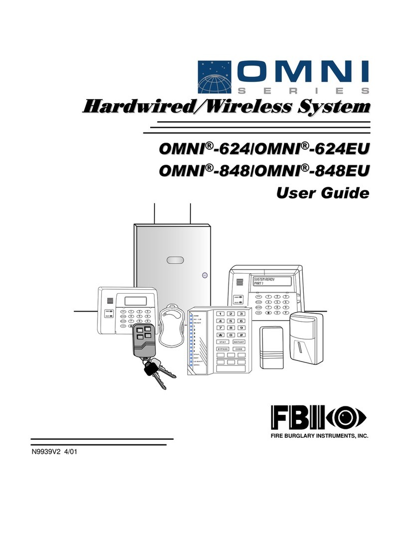
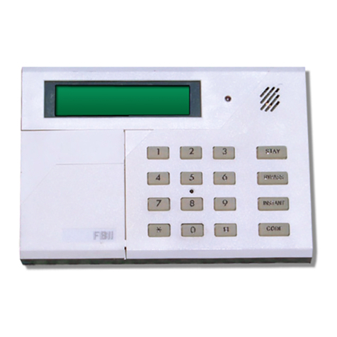
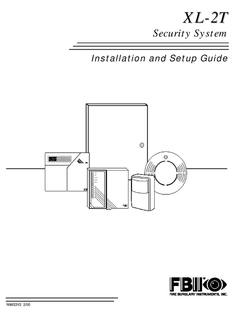
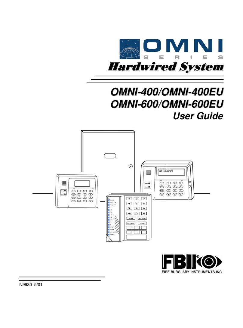
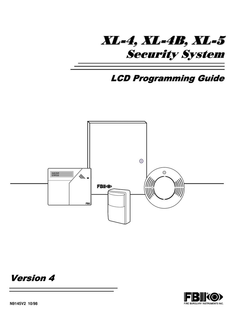
FBII OMNI-400 EU Assembly instructions

6HFXULW\6\VWHP
2
20
01
1,
,
2
20
01
1,
,
(
(8
8
2
20
01
1,
,
2
20
01
1,
,
(
(8
8
,QVWDOODWLRQDQG6HWXS*XLGH
ARMED
READY
1
4
7
2
5
8
0
3
6
9
#
STAY
BYPASS
INSTANT
CODE
ARMED
READY
1
4
7
2
5
8
0
3
6
9
#
STAY
BYPASS
INSTANT
CODE
1 3
2
4 6
5
7 9
8
#
0
STAY INSTANT
BYPASS CODE
ARM
AC / LB
READY
STAY
INST
LO BATT
SPRV.
N9979 5/01

ii
THANK YOU for your purchase of the
OMNI Security System.
The purpose of this manual is to give you a brief overview of the OMNI-400 and OMNI-
600 control panels, and to provide instructions for installing a basic system. FBII is always
available to serve YOU. Our SALES and TECHNICAL SUPPORT staff are available to
assist you in any way possible.
World Wide Web Address .........................................................HTTP://WWW.FBII.COM
FAX ...............................................................................................................516-921-4327
Sales
Inside the United States .....................................................................800-645-5430
Outside the United States...................................................................516-921-8666
Technical Support: (8 a.m.-8 p.m. E.S.T.)
Inside the United States .....................................................................800-645-7492
Outside the United States...................................................................516-921-8666
Before you call Technical Support, PLEASE be sure you:
•Check the wiring diagram and verify your connections.
•Check all fuses.
•Assure that the transformer and backup battery voltages are supplying the proper
voltage levels.
•Verify your programming information.
•Read this manual thoroughly.
•Consult the Troubleshooting Section of this manual.
•Note the proper model number of this product, and the version level (if known) along
with any documentation that came with the product.
•Have your company name and telephone number ready.
This information will allow us to service you more quickly and effectively. Please,
remember to BE PATIENT while waiting on the telephone; your call will be answered as
soon as possible.
FOR YOUR CONVENIENCE, a separate Programming Guide is included with this
manual. It provides space for listing entries for each programming question.

iii
Table of Contents
•••••••••••••••••••••••••••••••••••••••••••
SECTION 1 – INTRODUCTION............................................................................................................1-1
System Features ...................................................................................................................................1-1
Special Notes.........................................................................................................................................1-2
SECTION 2 – SYSTEM WIRING AND HOOKUP...............................................................................2-1
System Wiring Diagram.......................................................................................................................2-1
Terminal Connections...........................................................................................................................2-2
Auxiliary Device Current Draw Worksheet.........................................................................................2-5
Wiring Information for Keypads & Other Devices..............................................................................2-6
SECTION 3 – PC BOARD AND KEYPAD MOUNTING ....................................................................3-1
Mounting the OMNI-400/OMNI-400EU or OMNI-600/OMNI-600EU PC Board..............................3-1
Keypad Mounting Instructions ............................................................................................................3-2
SECTION 4 – SYSTEM CONFIGURATION ........................................................................................4-1
Hardwire Zones.....................................................................................................................................4-1
Relay/Trigger Outputs..........................................................................................................................4-2
Paging Feature......................................................................................................................................4-3
SECTION 5 – SYSTEM OPERATION...................................................................................................5-1
Power Up/System Reset........................................................................................................................5-1
Keypads.................................................................................................................................................5-1
Keypad Sounder....................................................................................................................................5-3
Keypad Addressing...............................................................................................................................5-4
Arming the System...............................................................................................................................5-5
User Code Programming......................................................................................................................5-7
User Deletion ........................................................................................................................................5-9
Keypad Emergency Conditions ............................................................................................................5-9
Quick Command Modes......................................................................................................................5-10
SECTION 6 – SYSTEM PROGRAMMING ...........................................................................................6-1
Programming Methods.........................................................................................................................6-1
System Default......................................................................................................................................6-1
Keypad Programming...........................................................................................................................6-1
Installer Modes Summary....................................................................................................................6-5
Data Entry via Keypads.......................................................................................................................6-9
Summary of System Programming....................................................................................................6-11
Programming Submode 1: SYSTEM OPTIONS................................................................................6-11
Programming Submode 2: ZONE PROGRAMMING / REPORT CODES........................................6-34
Programming Submode 3: Not used...................................................................................................6-40
Programming Submode 4: DESCRIPTOR PROGRAMMING ..........................................................6-40
SECTION 7 – SUMMARY OF KEYPAD FUNCTIONS ......................................................................7-1
User Functions......................................................................................................................................7-1
Installer Modes .....................................................................................................................................7-2

iv
SECTION 8 – CENTRAL STATION REPORTING FORMATS........................................................8-1
General Information.............................................................................................................................8-1
Standard (3x1 or 4x1)...........................................................................................................................8-2
Extended (3x1 Ext. or 4x1 Ext.)...........................................................................................................8-2
Partial Extended (3x1 Part. Ext. or 4x1 Part. Ext.)............................................................................8-3
3x2 or 4x2..............................................................................................................................................8-3
FBII Superfast (4x3x1).........................................................................................................................8-4
ADEMCO 4x1 Express .........................................................................................................................8-4
ADEMCO 4x2 Express .........................................................................................................................8-5
ADEMCO Point ID ...............................................................................................................................8-5
SECTION 9 – TROUBLESHOOTING...................................................................................................9-1
SECTION 10 – REGULATORY/LIMITATIONS STATEMENTS....................................................10-1

v
Conventions Used in This Manual
•••••••••••••••••••••••••••••••••••••••••••
Before you begin using this manual, it is important that you understand the meaning of the following
symbols (icons) and text note.
ULThese notes include specific information that must be followed if you are installing this system
for a UL Listed application.
These notes include information that you should be aware of before continuing with the
installation, and which, if not observed, could result in operational difficulties.
!
This symbol indicates a critical note that could seriously affect the operation of the system, or
could cause damage to the system. Please read each warning carefully. This symbol also
alerts the user to the possibility of physical harm if instructions are not followed as written
.
Note: These text notes are provided throughout the manual to provide informative information and
shortcut tips for the installer.

vi

1-1
SECTION 1
Introduction
•••••••••••••••••••••••••••••••••••••••••••
System Features
The OMNI-400, OMNI-400EU, OMNI-600, and OMNI-600EU are state-of-the-art microprocessor-based
control/communicators that provide 4 (OMNI-400 series) or 6 (OMNI-600 series) hardwired zones that
may be doubled. Programming can be performed through any of the compatible keypads, or the system
can be uploaded and downloaded remotely using the Compass Downloader Software. Additionally, the
software can be programmed to control remote actions, such as arming, disarming, bypassing, etc.
Programming options are stored in an Electrically Erasable Programmable Read Only Memory
(EEPROM). The EEPROM is nonvolatile, meaning that programmed instructions will not be lost in the
event of a loss of power.
Features of the OMNI-400, OMNI-400EU, OMNI-600, and OMNI-600EU include:
•4 (OMNI-400 series) or 6 (OMNI-600 series)
hardwire zones (all fully programmable,
including keyswitch)
•Hardwire zones can be configured as standard
or double-balanced, or can be set for zone
doubling (providing up to 8 hardwire zones for
the OMNI-400 series or 12 hardwire zones for
the OMNI-600 series)
•Separate panic switch or arm-only keyswitch
programmable hardwire input that follows
auxiliary key programming.
•Cross-zoning capability
•15 User Codes (either 4-digit or 6-digit codes
can be used)
•Up to 12 keypads (OMNI-LCD, XK-7LC,
OMNI-KP)
XK-108 keypads may also be used;
however, the system can only have XK-108
type keypads attached.
•Keypad programming and remote
programming via PC and modem
•Upload/download and remote commands
•10 programmable relay outputs (using optional
XL4705 modules)
•4 built-in programmable trigger outputs (2
triggers if relay module is used)
•Real-time clock (displays time and date via
LCD keypad) with reminder when clock needs
to be set
•CS test timer by event, time or both (1 hour, 1,
7, 27, 60, 90 days)
•Customer control of Chime mode and Pager
mode
•Quick Arming, Quick Bypass, and Quick Force
Arming
•CS reporting by zone
•False alarm prevention features: Crossed
Zones, Exit Error, Recent Close, Swinger
Shutdown
•Cancel Code and System Stabilization during
power-up
•Arming by keyswitch in Away or Stay mode
•Key Tamper/Lockout with optional CS
reporting

OMNI-400/OMNI-400EU and OMNI-600/OMNI-600EU Installation and Setup Guide
1-2
•3 methods of uploading/downloading: PC,
operator-initiated, and unattended
•Paging capabilities
•Auto-arming at a specific time of day with
capability to arm in either Away, Stay, or
Instant modes
•Dual entry timers
•128 Event History Log (alarms, troubles, low
battery, bypasses, central station (CS) test,
openings and closings) and keypad events
•3 emergency keypad conditions (Panic, Fire,
and Auxiliary)
•Restore transmission options: After Loop or
After Bell
•Fire zone reset through keypad
•Glassbreak reset through keypad
•Bell Test, Low Battery Test, AC loss and
communications failure
•Input power: 16.5VAC, 25VA; 12VDC, 4-7AH
•Output power: 12VDC, 500mA
•Bell output power: 12VDC, 1A
Special Notes
!
IMPORTANT - Failure to install and program this unit in accordance with the UL
requirement is a violation of the listing mark. For more information on UL Listings,
contact Underwriters Laboratories, Progress Department, 333 Pfingsten Road,
Northbrook, IL 60062.
UL Listings
The OMNI-400 and OMNI-600 are Residential (Household) control panels, and have been Listed by
Underwriters Laboratories for the following applications:
•UL 1023 Household Burglary
•UL 985 Household Fire Warning
FCC Registration Number: 5GBUSA-44003-AL-E
References to Programming Questions
Programming questions are grouped into 3 installer programming submodes, as follows:
1 – System Options
2 – Zone and Report Code Programming
3 – Not used
4 – Zone Descriptor Programming
Throughout this manual, programming question references without a submode designation pertain to
questions in Submode 1 (system options). Programming questions for other submodes include the
appropriate submode number.

2-1
SECTION 2
System Wiring and Hookup
••••••••••••••••••••••••••••••••••••••••••
•
System Wiring Diagram
1 2 3 4 5 6 7 8 9 10 11 12 13 14 15 19181716 20 21
22 23 24 25
++
+
-
-
2.2k
ZONE
1
2.2k
ZONE
2
2.2k
ZONE
3
2.2k
ZONE
4
2.2k
ZONE
5
2.2k
ZONE
6
+
_
TRIGGERS
+VBELL
GROUND
TRIGGER 2
TRIGGER 3 (OR CLOCK)*
TRIGGER 4 (OR DATA)*
TRIGGER 1
*IF XL4705 RELAY
MODULES USED.
PROGRAMMING
DEFAULT JUMPERS
OPTIONAL
TRIGGER
CABLE
XL4612TC
USEWITH
XL108 OR
OMNI-LCD,
OMNI-KP,
AND XK108L
TYPICAL DOUBLE
BALANCED ZONES
TYPICAL CONNECTION
FOR ZONE DOUBLING
89
7.5k
ZONE 2
3.3k
ZONE 1
2.2k
2.2k
2.2k
2.2k
2.2k
2.2k
789
TAMPER
CONTACTS
TAMPER
CONTACTS
TELCO CONNECTOR
(APPLICABLE ONLY
IN AUSTRALIA)
FIRE &
BURGLARY
ALARM
OUTPUT
(11.5 -
13.1VDC,
1A MAX)
STANDARD EOLR
SMOKE POWER (6+) & (5-)
12VDC REG., 50mA MAX
AUX PWR
(500mA
MAX)
AUX.
INPUT
BLACK ( )
YELLOW (DATA IN)
GREEN (DATA OUT)
RED (+)
BELL
GROUND
LUG
RED
GREEN
GRAY
BROWN
TELCO
HOME
MODEL 368
CORD TO
RJ31X OR
CA38A JACK
TRANSFORMER
16.5 VAC, 25VA
(CONNECT TO
24 HR. SOURCE)
SELF-CONTAINED
SIREN
OR
JP1 JP2
OMNI600-SOC-V0
12V, 4-6AH
BATTERY
MODEL 467 (4AH)
BLACK
RED
NOTES:
1. FOR UL INSTALLATIONS, USE TWO 4AH
BATTERIES CONNECTED IN PARALLEL
FOR MINIMUM STANDBY OF 24 HOURS.
THE TWO BATTERY CABLE (P/N F344)
IS OPTIONAL AND NOT INCLUDED WITH
THE PANEL.
2. 180 mA MAX, AUX. POWER (INCLUDING
KEYPADS CONNECTED TO TERMINALS
17-20) FOR UL INSTALLATIONS.
3. 650 mA MAX, ALARM OUTPUT FOR UL
INSTALLATIONS.
4. PANIC IS A N.O. INPUT THAT MAY BE USED
FOR A PANIC SWITCH OR ARM-ONLY
KEYSWITCH. CONNECT SWITCH BETWEEN
TERMINALS 16 (+) AND 17 (-).
5. ZONES 5 AND 6 (TERMINALS 13-15) ARE
NOT APPLICABLE FOR THE OMNI-400 AND
OMNI-400EU.
TO PREVENT RISK OF ELECTRICAL
SHOCK, DE-ENERGIZE THE SYSTEM
CONTROL UNIT AND DISCONNECTTHE
TELEPHONE LINES BEFORE SERVICING
THIS UNIT.
WARNING

OMNI-400/OMNI-400EU and OMNI-600/OMNI-600EU Installation and Setup Guide
2-2
SYSTEM STABILIZATION MODE: When powering up a system that was previously armed when
power was removed, the system will enter a 2-minute stabilization period. This 2-minute interval is
used to allow motion detectors to stabilize. “PLEASE STAND BY” and “POWER UP DELAY” are
displayed on the OMNI-LCD and XK-7LC keypads. “PL” is displayed on the OMNI-KP keypad, and
the Armed LEDs on all keypads are lit. All LEDs on the XK108 keypad are lit.
Terminal Connections
1 & 2 — TRANSFORMER: Connect the 16.5VAC 25VA transformer, utilizing 18AWG (1mm dia.) or
larger wire at a distance not to exceed 15 feet (4.5m) from the panel, to an unswitched source of
AC mains power (120 or 220VAC).
The system can supply up to 1.8 amps of total current.
Do not use any other rating transformer, as this may result in improper operation or damage to the
unit.
The “AC/LOW BAT” keypad LED remains ON while AC power is present. If an AC loss occurs, the
“AC/LOW BAT” LED turns off immediately. If AC power remains OFF for the period programmed
in Programming Submode 1, Question 15, Location 3, the system pulses the keypad buzzer and
transmits a power-loss message to the central station, if programmed to do so. THE KEYPAD
BUZZER CAN BE SILENCED by entry of any valid user code. When AC restores, the “AC/LOW
BAT” LED lights immediately, and a Restore code is reported, if programmed.
3(+) & 4(–) — BELL OUTPUT: The total output power available for sounding devices is 1 amp (650mA
for UL installations) at 11.5 - 13.1VDC. These terminals will deliver CONSTANT output on
BURGLARY, AUDIBLE PANIC, and BELL TEST. On a FIRE condition, a PULSED or TEMPORAL
output can be generated. There are separate bell cutoff times programmable for burglary and fire
conditions within the programming sequence. For UL Household Fire Warning System
installations, the speaker must be mounted indoors for best audibility. Also, for UL installations,
use only one bell.
NOTE: Before connecting sounding devices, please consult their specifications for proper current
draw. Otherwise, the bell fuse (F1) may be blown.
NFPA 72 REQUIREMENT: All the
interconnecting pathways (cable,
wire, etc.) between the alarm
system initiating device (control
panel) and the signaling device
(bell, speaker, siren, etc.) shall be
monitored for an occurrence of an
open circuit, which prevents the
normal operation of the system. An
occurrence of an open circuit shall
be indicated by a distinctive trouble
signal.
BELL SUPERVISION (Bell) - To meet the NFPA 72 requirement,
program Question 09, Location 3, in Programming Submode 1
for bell supervision. The bell is then supervised for an open
circuit (not a short circuit) across the bell output terminals; the
keypad will indicate that a bell supervision condition has
occurred and bell supervision is reported to the CS if enabled
(Programming Submode 2, Question 25, Locations 1 and 2). If
the bell is already ringing, the supervision will not take effect
until after bell cutoff time. Refer to the following diagram:

Section 2. System Wiring and Hookup
2-3
3 (+)
OMNI600-001-V0
4 (–)
MECHANICAL
BELL
BELL
OUTPUT
SIREN SUPERVISION (Self-Contained Siren/Speaker) -(Not for use in UL installations.) To meet
the NFPA 72 requirement, program Question 09, Location 3, in Programming Submode 1 for bell
supervision. The siren is then supervised for an open circuit (not a short circuit) across the bell
output terminals; the keypad will indicate that a supervision condition has occurred and bell
supervision is reported to the CS, if enabled (Programming Submode 2, Question 25, Locations 1
and 2). If the siren is already sounding, the supervision will not take effect until after bell cutoff
time.
NOTE: Use FBII models ZR-815C, ZR-815EC, or ZR-830EC. See the following diagram:
OMNI600-002-V0
3 (+)
4 (–)
BELL
OUTPUT
SIREN/SPEAKER
6 (B+) & 5 (–) — SMOKE DETECTOR POWER: This system will accept 9.5–12VDC 4-wire smoke
detectors only. Approximately 50mA of current is available at these terminals for powering all
detectors and/or an EOL relay (i.e., FBII Model 620). For UL installations, see wiring diagram for
hookup.
These terminals adhere to the fire verification and reset logic, which is explained in the System
Programming section of this manual. The smoke detector power may be manually reset by clearing
the alarm memory and then entering a valid user code.
6 (B+) & 4 (–) — REGULATED POWER (11.5 –13.1VDC): The total regulated output power for
motion detectors and other external devices is 500mA at 11.8 - 12.5V for residential applications, or
12.0 - 12.5V for commercial applications, with less than 100 mVPP ripple. The total regulated
output capacity of the control panel includes the power available from these terminals (6 and 4) as
well as the power used by the keypads (20 [+] and 17 [–]) and smoke detectors (5 [–] and 6 [+]).
Therefore, to determine the total power available from these terminals, subtract the power
consumed by the keypads and smoke detectors. NOTE: For UL installations, total current cannot
exceed 180mA including the keypads connected to terminals 17 through 20.

OMNI-400/OMNI-400EU and OMNI-600/OMNI-600EU Installation and Setup Guide
2-4
ZONE INFORMATION (HARDWIRED ZONES):
7 (+) & 8 (–) Zone 1 [Default = DELAY]
9 (+) & 8 (–) Zone 2 [Default = INTERIOR]
10 (+) & 11 (–) Zone 3 [Default = INSTANT]
12 (+) & 11 (–) Zone 4 [Default = INSTANT]
13 (+) & 14 (–) Zone 5 [Default = INSTANT] (OMNI-600/600EU ONLY)
15 (+) & 14 (–) Zone 6 [Default = INSTANT] (OMNI-600/600EU ONLY)
Normally-closed devices may be wired in series; normally-open devices may be wired in parallel. A
2.2k-ohm end-of-line resistor can be installed on all zones. (Refer to the wiring diagram.) The
standard loop response time is 280mS on all zones. The factory default values for each zone are
listed in the table above; however, any zone can be programmed for the following types: delay,
perimeter, interior, fire, 24-hr. alarm, or 24-hr. trouble. Further explanation of the zone types can
be found in the System Programming section of this manual. See the “Hardwire Zones” paragraph
in Section 4: System Configurations for information on zone doubling (to increase the number of
available hardwire zones) and the use of double-balanced zones.
NOTE: Loop response is defined as the minimum time required for a fault to trip a zone.
16 (+) & 17 (-) — AUXILIARY INPUT: This terminal is a normally-open terminal that may be wired to
a panic switch or “arm-only” keyswitch. When using a panic switch or arm-only keyswitch, connect
one side of the switch (+) to terminal 16 and the other side of the switch (–) to terminal 17. When
the switch is activated, the system will respond in the same manner as if you had depressed keypad
auxiliary keys 1 and 3 (programmed in Programming Submode 1, Question 18, L1 and L2). For
additional information on auxiliary keys, see “Keypads” in Section 5: System Operation.
17 (BLK), 18 (YEL), 19 (GREEN) & 20 (RED) — KEYPADS: Up to 12 keypads may be wired to these
terminals. The connections are as follows: 17 (BLACK = negative), 18 (YELLOW = data in), 19
(GREEN = data out) and 20 (RED = positive power). Refer to the table in the “Auxiliary Device
Current Draw Worksheet” paragraph of this section to obtain keypad current draw information.
NOTE: In some installations, it may be necessary to use shielded wire to prevent radio frequency
interference.
21 — EARTH GROUND: Connect this grounding lug to a cold-water pipe utilizing 18AWG (1mm dia.)
wire at a distance of no greater than 15 feet (4.5m). Use a noncorrosive metal strap firmly secured
to the pipe to which the lead is electrically connected and secured. If the premises pipes terminate
in PVC, this terminal must be connected to a 6-foot (2m) grounding rod.
22 (BRN), 23 (GRAY), 24 (GREEN) & 25 (RED) — TELEPHONE LINE: Connect the RJ31X cord as
follows: 22 (BROWN = Home Tip), 23 (GRAY = Home Ring), 24 (GREEN = Telco Tip), 25 (RED =
Telco Ring). Insert the plug into a USOC RJ31X Jack (or a CA31A Jack for Canadian installations).
The FCC registration number is 5GBUSA–44003–AL–E, and the ringer equivalence is 0.1B. The
system should not be connected to party lines or coin-operated phones.
If this control panel will be used for uploading, downloading, or remote-command applications, the
telephone line connected to the control panel must not be shared with a fax machine or modem.
Furthermore, this device should not be connected to a phone line that has Call Waiting, unless the
Call Waiting Interrupt numbers are programmed into the panel dialing sequence.

Section 2. System Wiring and Hookup
2-5
BACKUP BATTERY: The RED (+) and BLACK (–) flying leads must be connected to a 12VDC 4–7AH
lead acid battery, to serve as backup power in the event of AC loss.
A battery test occurs approximately every minute. Low-battery condition occurs at nominal 11VDC.
The keypad AC/LOW BAT LED and buzzer will pulse slowly when a low-battery condition is
detected. The system reports this condition to the CS if programmed to do so. There is also an
option that prevents the system from arming if a low battery has been detected (see Question 11,
L2). Battery restoral will occur within 4 minutes, at the next battery test. The buzzer may be
silenced by entry of any valid user code.
NOTE: For UL installations, use two 4AH batteries connected in parallel.
TRIGGER/RELAY OUTPUTS: The control panel has four built-in programmable trigger outputs. In
addition, up to two XL4705 Relay Modules can be connected, providing 10 additional programmable
relay outputs. If the Relay Modules are used (enable modules in Programming Submode 1, Question
09, L2), then built-in triggers 3 and 4 are no longer used as trigger outputs, but serve as clock and
data inputs for the relay modules. See Programming Submode 1, Questions 23–29, for valid
trigger/relay types and programming.
NOTE: In order to connect devices to the triggers, use connector XL4612TC (trigger cable). Connect
to terminal P1 VBELL to obtain a POSITIVE reference point.Triggers 1, 2, 3, and 4 (only 1 and 2
when using XL4705) will go to a negative ground potential when active. For UL installations, the
trigger outputs shall be connected to devices rated to operate over the range from 10.1–14.0VDC at
50mA.
Auxiliary Device Current Draw Worksheet
DEVICE CURRENT DRAW
FOR EACH NUMBER
OF UNITS TOTAL CURRENT
FOR ALL UNITS
Control Panel 65mA 1 65mA
OMNI-LCD (Backlight Off/On) 35mA/81mA
XK-7LC 65mA
OMNI-KP (Backlight Off/On) 28mA/45mA
XK-108 5mA
PIR **
Smoke Detector **
Glassbreak Detector **
**
**
TOTAL CURRENT FOR ALL DEVICES =
(500mA max.)***
** If the system is
using devices such as
PIR's, smoke
detectors, etc., refer
to the specifications
for that particular
device's current draw.
If the total current
draw for all devices
exceeds 500mA, use
an additional power
supply.
*** For UL
installations, do not
exceed 180mA.
NFPA, UL, and the California State Fire Marshal require the backup battery to provide power
for 24 hours. The maximum aux. power will vary by the ampere/hour rating of the battery used:
5AH = 95mA; 7AH = 180mA; 8AH = 210mA.

OMNI-400/OMNI-400EU and OMNI-600/OMNI-600EU Installation and Setup Guide
2-6
Wiring Information for Keypads & Other Devices
If single or multiple devices are connected on a single 4-wire or 2-wire run ("daisy chained") to the
control terminals, do the following:
Determine the current drawn by the unit(s) connected to the single-wire run, then refer to the Wiring
Run Table below to determine the maximum wire length that can be safely used for each wire size.
In some cases, the total current drawn may result in a value not shown in the table. For example, if you
plan to use #22 gauge (0.64mm) wire and the total current drawn is 400mA (a value between 300mA
and 500mA), the maximum wire length you should use is approximately 65 ft. or 20m (a length
between 50 and 80 ft or 15m and 24m). Other maximum wire lengths for values of current not shown in
the table can be calculated in a similar manner.
Maximum wire lengths for a device that is "home run" to the control can also be determined from the
table, based on the current draw of that device alone.
Wiring Run Table For Devices Drawing Power From Terminals 23 (+) & 20 (–)
TOTAL CURRENT DRAWN BY ALL UNITS ON A SINGLE WIRE RUN
WIRE SIZE 50mA or less 100mA 300mA 500mA
#22 (0.64mm) 500 ft. (152m) 250 ft. (76m) 80 ft. (24m) 50 ft. (15m)
#20 (0.8mm) 750 ft. (229m) 380 ft. (116m) 130 ft. (40m) 80 ft. (24m)
#18 (1mm) 1300 ft. (396m) 650 ft. (198m) 220 ft. (67m) 130 ft. (40m)
#16 (1.3mm) 2000 ft. (610m) 1000 ft. (305m) 330 ft. (100m) 200 ft. (70m)
Examples:
1. What is the maximum distance from the control panel for one keypad drawing 30mA using #20
gauge (0.8mm dia.) wire?
Using the table above, the keypad can be placed no farther than 750 ft. (230m) away from the panel
(50mA or less).
2. What is the maximum distance for 5 smoke detectors drawing 0.25mA (50µA each) using #22 gauge
(0.64mm dia.) wire connected in a single-wire run?
Using the table above, the farthest smoke detector can be placed no more than 500 ft. (150m) away
from the panel.

3-1
SECTION 3
PC Board and Keypad Mounting
•••••••••••••••••••••••••••••••••••••••••••
Mounting the OMNI-400/OMNI-400EU or OMNI-600/OMNI-600EU PC Board
NOTE: The door of the metal cabinet may be removed to make it easier to install the control panel.
Remove the door as follows:
1. With the cabinet laying on a flat surface, swing open the door to its full-open position.
2. Slide the door out of its retaining slots in the cabinet and store in a safe place.
BEFORE MOUNTING PRINTED CIRCUIT BOARD, BE CERTAIN THAT APPROPRIATE METAL
KNOCKOUTS HAVE BEEN REMOVED FROM THE METAL CABINET. DO NOT ATTEMPT TO REMOVE
THE KNOCKOUTS AFTER CIRCUIT BOARD HAS BEEN INSTALLED.
3. Insert top of circuit board into slots at top of cabinet. Make sure that circuit board rests in slots as
indicated in the diagram shown below.
4. Swing base of circuit board onto the raised cabinet tabs.
5. Slide the supplied ground lug between the printed circuit board and the raised cabinet tab as shown
in Detail B.
6. Secure the sides of the PC board to the enclosure using the 2 screws provided.
BOARD
SUPPORTING
SLOTS
DETAIL A
SIDE VIEW
OF BOARD
SUPPORTING SLOTS
DETAIL B
SIDE VIEW
OF MOUNTING
SCREW
pcb_mount-007-V0
CIRCUIT
BOARD
GROUND
LUG
CIRCUIT BOARD
CABINET
CONTROL CIRCUIT BOARD
SCREW

OMNI-400/OMNI-400EU and OMNI-600/OMNI-600EU Installation and Setup Guide
3-2
Keypad Mounting Instructions
The security system is compatible with the following addressable keypads:
•LCD (alpha) keypad: OMNI-LCD
•LCD (alpha) keypad: XK-7LC
•Fixed-word keypad: OMNI-KP
•LED keypad: XK-108
The system can accept a mixture of OMNI-LCD, XK-7LC, and OMNI-KP keypads. However, if
you use an XK-108 keypad, all additional keypads on the system must also be XK-108’s.
See the Installation Instructions provided with the keypads for mounting procedures.

4-1
SECTION 4
System Configuration
•••••••••••••••••••••••••••••••••••••••••••
Hardwire Zones
Hardwired Zones: Consist of 4 (OMNI-400 series) or 6 (OMNI-600 series) on-board hardwired zones.
System options allow for all hardwired zones to be configured as E.O.L., N.C., N.O., double-balanced, or
configured for zone doubling.
Standard Mode: Each zone may be programmed as EOL 2.2k, normally closed or normally open. Zone
4 (OMNI-400 series) or zone 6 (OMNI-600 series) can be set as a fast zone (for normally closed loops
only). Refer to the connection diagram for wiring connections.
Double-Balanced Zones: In this configuration, tampers may be detected for both shorted and opened
loops. Tamper conditions will cause an alarm if armed and a fault if disarmed, with visible tamper
indication on the keypad. Up to nine 2.2k resistors are wired in series across normal shorted detectors,
with one 2.2k end-of-line resistor. Any device that opens adds 2.2k to the loop causing an alarm. If the
loop resistance exceeds 22k, the loop is considered tampered. If the system is set for double-balanced,
this will override any individual zone settings.
Zone Doubling: Up to 8 (OMNI-400 series) or 12 (OMNI-600 series) zones may be used as hardwired
when this zone option is selected. The zones are consecutive on each physical loop. The low zone uses a
3.3k resistor and the next zone uses a 7.5k resistor. The loop is wired with normally shorted devices in
parallel. For example, if zone doubling is programmed to begin on Zone 1, then Loop 1 uses the 3.3k
resistor for Zone 1 and the 7.5k resistor for zone 2; Loop 2 contains zones 3 and 4, etc. In Zone
programming (Programming Submode 2, Question 32, L1 and L2), the value of 00 disables zone
doubling; otherwise, program the first loop that zone doubling is to begin. For example, programming a
“5” in the zone doubling question means that loop 5 will contain zones 5 and 6, and loop 6 will contain
zones 7 and 8.
Cross Zoning: Two groups of 2-zone crosses can be programmed. Two cross-zone timers are
programmable (Question 35, L3 [timer 1] and L4 [timer 2] in Programming Submode 2: Zone
Programming) in 15-second increments (15 sec. to 4 min.) Cross-zone processing only occurs when
controlled zones are armed or on 24-hour zones.
Cross zoning functions in either of 2 ways:
•If the group contains 2 different zones, when the first zone in the group is tripped, the cross-zone
timer loads and starts counting. An alarm will occur if:
The other zone in the same group trips before the timer reaches 0. This causes an alarm on the
second zone to trip. The first zone to trip will only go into alarm if it is still violated at the time
that the second zone causes an alarm.
or
The timer expires and the zone that started the timer is still violated and has not restored
during the entire timing cycle.

OMNI-400/OMNI-400EU and OMNI-600/OMNI-600EU Installation and Setup Guide
4-2
•The zone is crossed to itself (e.g., Programming Submode 2, Question 33 is programmed as 0101 –
Zone 1 crossed to itself) and the zone has tripped 3 times within the timing period (Pulse counter).
Relay/Trigger Outputs
The system allows up to 12 programmable outputs. It provides 4 built-in triggers with the option of
adding up to two XL4705 Relay Modules (which provide up to 10 relay outputs). If the relay modules
are used, they must be enabled during programming (Submode 1, Question 09, Location 2). When using
relay modules, built-in triggers 3 and 4 no longer function as triggers, but serve as clock and data
inputs for the modules. The remaining 2 built-in triggers provide a total of up to 12 programmable
outputs. See Programming Questions 23–29 in Submode 1 for individual trigger programming options.
Each XL4705 Relay Module provides five form C relays. Each module must be assigned a unique
module address (0 or 1) using its DIP switches. The module addresses allow the system to identify the
specific relay numbers being used according to the following table:
Module
Number Module DIP
Address Relay
Numbers Program
Question
1 0 1–5 Q23–25
2 1 6–10 Q25–27
Built-in triggers 1–4 are programmed in Questions 28 and 29.
NOTE: If the system uses relay modules, only triggers 1 and 2 are available.

Section 4. System Configuration
4-3
Connect the Relay Modules as shown:
1 2 3 4 5 6 7 8 9 1011121314151617181920
GND DATA CLK
+
12V
NO NC C NO NC C NO NC C NO NC C NO NC C
Relay 1 Relay 2 Relay 3 Relay 4 Relay 5
XL4705
RELAY
MODULE
CONNECT
TO EARTH
GROUND
TO AUX POWER
TERMINALS
CONNECT TO TRIGGER 4
CONNECT TO TRIGGER 3
DATA
CLOCK
12V
REFER TO
“DIP SWITCH ADDRESSING”
TABLE FOR SETTINGS
DIP SWITCHES
DIP SWITCH 1: In the ON position, inverts Relays 2 and 4, e.g.,
if wired for normally closed (N.C.), relay will
change to normally open (N.O.), and vice versa.
SW1
ON
OFF
1234
DIP SWITCHES
SHOWN IN “OFF”
POSITION
Trigger Address Switch 2 Switch 3 Switch 4
1–5 OFF OFF OFF
6–10 ON OFF OFF
DIP SWITCH ADDRESSING
*
Modules may have to be powered from a separate
12V power source if the total current drawn by the
relay modules exceeds the current available from
the control panel’s Auxiliary Power output.
SW1
USE TWISTED
PAIR FOR
THESE WIRES
(4)
(6)
OMNI600-004-V0
XL4705 Current Advisory: Standby = 16mA
Each active relay = 40mA
Total current drain with all five relays active = 200mA
If a separate power supply is used to power the module, you must
connect the power supply ground to the control panel ground terminal.
Paging Feature
Summary: A 16-digit phone number to dial for paging, which the end user or installer can reprogram,
is entered in Submode 1, Question 04. The number of times the pager number is dialed is installer-
programmable from 1–3 times. The installer also selects which events may cause a page. Four
conditions may be selected: (1) zone alarms, (2) zone troubles, (3) openings, and (4) closings.
Additionally, paging may be turned on or off for opening and closing.
NOTE: Only one event is paged-based on the priority described next.
Paging Alarms, Troubles, Open, and Close:
Alarms take priority over troubles, troubles take priority over opens, and opens take priority over
closes.
For pager opening or closing to occur, the following conditions must exist:
•The system must not have an alarm or trouble condition.
•The system must have the open or close enabled (Submode 1, Question 14, L4).

OMNI-400/OMNI-400EU and OMNI-600/OMNI-600EU Installation and Setup Guide
4-4
•The system must have the open/close enable set by using the #8 command (see below).
•The phone number must be enabled (Submode 1, Question 04).
•The page attempts option must be set (Submode 1, Question 10, L3).
User Enables and Options:
#8 – Allows the end user to turn on or off open and close pages. This will not affect alarm and trouble
pages if enabled. Also, the installer must have enabled opens and/or closes to page.
LCD – Displays if open/close pages are on/off. Press [#] to toggle, press [✱] to exit.
LED/Fixed Word – Toggles if open/closes will send a page.
#58 [code]†– End user function to change the pager number. This mode times out in 10 seconds
without saving the phone number if no key is pressed, or exits without saving if the [✱] key is pressed.
† Entry of the user code is optional.
Key functions:
[✱] Key – Exits mode without saving.
[#] Key – Saves new phone number and blanks digits from last digit entered to end
[Code] key – Enters a
$
C
#
in the string, which gives an additional 2-second pause.
LCD – Displays 16-digit phone number. Enter new phone number and press [#] to save, or press [✱] to
exit.
For LCD pads, press another key after saving the number, and the #8 user pages enable is displayed.
LED/Fixed Word – “ACK” sound heard. Enter the phone number using digits 0–9 and press [#] to
save, or press [✱] to exit.
Installer Pager Options:
Submode 1, Question 14, L4: Contains the pager options and the open/close enable that may be
disabled by the #8 command.
Paging/Beeps Sequence: The paging will not begin until the dialer is off and dialer delay is not
active. The system checks if any event needs to be dialed. The page/beeps are dialed 1, 2, or 3 times. If
pager attempts are 0, paging is disabled. The pager format is as follows:
Account Event Zone/User Terminator
1234 [0, 1, or 9] [000-255] [#]
where: Opening = 0
Closing = 1
Alarm or Trouble = 9
This data is transmitted 2 times with a 5-second pause between rounds.
This manual suits for next models
3
Table of contents
Other FBII Security System manuals

FBII
FBII OMNI-848EU User manual

FBII
FBII OMNI-624EU User manual

FBII
FBII XL-5 User manual

FBII
FBII XL4600DL User manual

FBII
FBII LEGEND 7100 User manual

FBII
FBII Star XL4800 EZ User manual

FBII
FBII XL-2T Assembly instructions

FBII
FBII XL-21 User manual

FBII
FBII XL-2 User manual

FBII
FBII LEGEND SERIES User manual