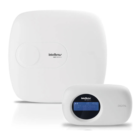
Intelbras AMT 1000 SMART User manual

Installation guide
AMT 1000 SMART
AMT 2018 E SMART
English


ATTENTION: this product has access password. For your safety, it is important that you change it as soon as
you install the product, or check with your technician the passwords set, which ones the users have access and
the recovery methods.
AMT 1000 SMART and AMT 2018 E SMART
Monitored alarm unit
Congratulations, you have just purchased a product with Intelbras quality and safety.
It is an installation guide for units AMT 1000 SMART and AMT 2018 E SMART. For further information, refer to
Installation Manual and Technical Description on Intelbras website.

Summary
1. Technical specications 5
2. Installation 6
2.1. Connection schematic .......................................................................7
2.2. Network cable connection connector ............................................................8
2.3. Busbar devices.............................................................................8
2.4. Auxiliary output ...........................................................................10
2.5. Register wireless sensors and remote controls through the following buttons:
Sensor and Control..............10
2.6. Communication with module FXO 8000.........................................................12
2.7. Communication with modules XG 2G, XG 3G and XG 4G ............................................13
2.8. Zone input...............................................................................13
3.Cloud connection 17
4. Reset Options 17
4.1. Temporary reset by siren short circuit ...........................................................17
4.2. Temporary reset by Control and Sensor registration buttons ..........................................17
4.3. Programming mode reset ...................................................................17
4.4. Wireless device reset .......................................................................17
5. Keyboard indications 17
5.1. Problem display and view....................................................................18
6. Passwords 18
6.1. Alarm unit activation/deactivation .............................................................18
7. View zone status 19
8. Quick Keys 19
9. Event map 20
10. Programming 21
11. Update 41
11.1. Update through keyboard ..................................................................41
11.2. Update via Remote AMT ...................................................................41
11.3. Update through USB .....................................................................41
Warranty Term 42

5
1. Technical specications
Model AMT 1000 SMART AMT 2018 E SMART
Eth connection Yes and provided in the unit Yes and provided in the unit
Eth speed 100 Mbps and Full Duplex 100 Mbps and Full Duplex
Version update Remotely via Eth Remotely via Eth
Local via USB Local via USB
Monitoring servers 2 different servers 2 different servers
Cloud dedicated server Yes and independent from monitoring servers Yes and independent from monitoring servers
Indicating LED of connection status
with servers Yes Yes
Event protocol Contact ID Contact ID
Remote programming Yes, through Remote AMT and Mobile Remote
AMT
Yes, through Remote AMT and Mobile Remote
AMT
User app Yes, AMT Mobile V3 Yes, AMT Mobile V3
DHCP Yes Yes
Connection through cellular network Yes, through XG 2G or XG 3G or XG 4G Yes, through XG 2G or XG 3G or XG 4G
Calls through chip Yes, for up to 5 different numbers Yes, for up to 5 different numbers
IPv4 Yes Yes
Buffer size 256 events 256 events
Allows telephone line Does not allow Yes, through FXO 8000
Partitioning 1 partition 2 partitions
Stay mode Full Full and by partition
User quantity 64 64
Temporary users Yes Yes
Remote control quantity 61 61
Button quantity by remote controls 4 4
Programmable features of buttons of
remote controls Yes and independent by button Yes and independent by button
Wireless panic 61 61
Zones
Total 36 Total 48
8 zones in the unit 16 zones in the unit
2 zones by keyboard, total 4 2 zones by keyboard, total 8
24 wireless zones 24 wireless zones
Zone duplication Enabled in unit zones Enabled in unit zones
On Input yes yes
Wireless sensor supervision Yes Yes
Wireless sensor open port detection Yes Yes
Unit built-in receiver Yes Yes
Wireless system modulation OOK and FSK OOK and FSK
Busbar keyboard quantity 2 keyboards 4 keyboards
Busbar receiver quantity 2 receivers 4 receivers
Busbar cabling 4x26 AWG (minimum) 4x26 AWG (minimum)
Busbar cabling maximum distance 100 meters 100 meters
Busbar cabling maximum impedance 40 Ohms 40 Ohms
Zone cabling maximum impedance 40 Ohms 40 Ohms
Busbar device supervision Yes, against short circuit and overload Yes, against short circuit and overload
AUX output current Programmable (max. 1 A) Programmable (max. 1 A)
SIR output current Programmable (max. 1.5 A) Programmable (max. 1.5 A)
PGM quantity 2 50 mA / 12 Vdc 2 50 mA / 12 Vdc
Unit language Portuguese and Spanish, and it is possible
to change by programming
Portuguese and Spanish, and it is possible
to change by programming
System supply Fullrange , from 85 to 265 Vac Fullrange , from 85 to 265 Vac

6
XG 2G XG 3G XG 4G
Technology GPRS 3G and GPRS 4G and GPRS
Chip quantity 2 Chips 2 Chips 2 Chips
Antenna 0 dBi external 0 dBi external 0 dBi external
Frequency Quadri band:
850/900/1800/1900 MHz
Penta band:
800/850/900/1900/2100 MHz
Hexa band:
700/850/900/1800/2100/2600 MHz
Chip dialing Allows Allows Allows
Remote setting Allows Allows Allows
Protocol TCP/IP TCP/IP TCP/IP
2. Installation
JP1
Zonas Zonas Zonas Zonas
1 2 3 6 754
8
9
1112 10
13
1. Supply connector originated from keyed power supply;
2. Battery connector;
3. Siren output;
4. Network cable connection connector (Ethernet);
5. Zone input;
6. Busbar input T1 and T2;
7. Auxiliary input (AUX);
8. Communication module connector via telephone line FXO 8000 (FXO not included);
Remark
: available feature only in AMT 2018 E SMART.
9. PGM programmable output;
10. Jumper to select Non-Supervised (OOK) or Supervised (FSK) Modulation;
11. Product local update connector;
12. Remote control and wireless sensor registration buttons;
13. Connector to modules XG 2G, XG 3G and XG 4G (not included).

7
2.1. Connection schematic
JP1
Zonas Zonas Zonas Zonas
Alarm unit
Alarm unit power supply

8
2.2. Network cable connection connector
2.3. Busbar devices
Used to keyboard and wireless receiver communication. Contact ID event device indexes include:
Device Index
Keyboard 1 to 4 1 to 4
Receiver 1 to 4 5 to 8
2.3.1. Keyboards
Keyboard connection
Keyboard connector Wire color
Vdc +12V supply Red wire
Grounding or (-) Black wire
Busbar T1 Green wire
Busbar T2 Yellow wire
Zone 9 (Z9) or wired Single Zone (*) Blue wire
Zone 10 (Z10) or wired Single Zone (*) White wire
Common to zones Black wire
It is recommended to use unit AUX output to supply the keyboard, but, if an external power supply has to be used,
power supply negative (-) must be connected to AUX negative.
Jumper position in Address connector denes which will be Keyboard 1, Keyboard 2, Keyboard 3 and Keyboard 4.
4
3
2
1
4
3
2
1
4
3
2
1
4
3
2
1
Keyboard 4 Keyboard 3 Keyboard 2 Keyboard 1
Address
Address
Address
Address
The following table provides zone identication according to keyboard jumper addressing.
AMT 1000 SMART
Keyboard Blue wire White wire
Keyboard 1 Zone 09 Zone 10
Keyboard 2 Zone 11 Zone 12
Keyboard 3 Does not allow keyboard
Keyboard 4 Does not allow keyboard
AMT 2018 E SMART
Keyboard Blue wire White wire
Keyboard 1 Zone 09 Zone 10
Keyboard 2 Zone 19 Zone 20
Keyboard 3 Zone 21 Zone 22
Keyboard 4 Zone 23 Zone 24

9
2.3.1. Wireless signal receiver (RF)
Wireless device receiver connection
With this receiver, it is possible to use wireless sensors and remote control with the following characteristics:
» Work in OOK modulation (non-supervised system) or in FSK modulation (supervised system).
» Operation frequency 433.92 MHz
» Bit transmission rate 1.886 Kbps.
It is important that wireless sensors and remote controls of other manufacturers use the same Intelbras product coding.
If other coding is used, the products will not be compatible with such alarm units.
In order to perform XAR 40000 SMART connection in the unit, it is recommended to use a 4 × 26 AWG cable, 40 Ohms
maximum impedance and 100-meter maximum distance between the unit and the receiver. Greater than 26 AWG
cabling can be used.
Position of jumpers JP1, JP2, JP3 and4 dene which will be Receiver 1, Receiver 2, Receiver 3 and Receiver 4.
Busbar selection must be performed in jumper JP5 and needs to be in position T1 T2, as units AMT 1000 SMART and
AMT 2018 E SMART have only this busbar. Impedance jumper JP6 needs to be open.
Selection to Non-Supervised mode (OOK modulation) or Supervised mode (FSK modulation) must be performed in
jumper JP7.

10
OOK modulation FSK modulation
2.4. Auxiliary output
It is recommended to use a 4 × 26 AWG cable, 40 Ohms maximum impedance and 100-meter maximum distance
between the unit and connected accessories. Greater than 26 AWG cabling can be used.
2.5. Register wireless sensors and remote controls through the following buttons:
Sensor and
Control
Units AMT 1000 SMART and AMT 2018 E SMART enable performing wireless sensor registrations through the button
Sensor
and registering remote controls through the button
Control
found in the unit main board.
Key Sensor
Key Control
Unit built-in receiver operation modulation must be selected through jumper JP1 of the unit.This jumper enables choos-
ing Non-Supervised (OOK modulation) or Supervised (FSK modulation) mode.
Selection of Non-Supervised setting (OOK)
(JP1= 1 and 2), LED (LD13) will blink green
every time a device is transmitted:
Selection of Supervised setting (FSK) (JP1= 2
and 3), LED (LD13) will blink red every time
a device is transmitted:

11
2.5.1. Wireless sensor registration
1. Upon selecting the modulation, press the Sensor button in the unit until LED (LD13) is lit in selected modulation color
2. Perform wireless sensor actuation:
» Registered: LED will turn off and a sound signal of 2 quick conrmation beeps will be released in the keyboard
being used;
» Not Registered: LED will turn off and a sound signal of 1 long error beep will be released in the keyboard being
used.
2.5.1. Remote control registration
1. Upon selecting the modulation, press the button
Control
in the unit until LED (LD13) is lit in selected modulation color
2. Perform remote control actuation:
» Registered: LED will turn off and a sound signal of 2 quick conrmation beeps will be released in the keyboard
being used;
» Not registered: LED will turn off and a sound signal of 1 long error beep will be released in the keyboard being used.
When the registration is performed through button Control of unit board, the remote control takes over the next free
user and its buttons take over a pre-set function, as listed below (functions can be edited in programming address
Enter + 65
).
» Non-partitioned system
» Partitioned system (only to AMT 2018 E SMART)
A
B
Xac 2000
A
B
Xac 4000
XAC 2000
Non-partitioned system Partitioned system
Power button Activates and deactivates totally Activates an deactivates partition B
Button A Activates and deactivates totally Activates and deactivates totally
Button B Activates Stay and deactivates totally Activates an deactivates partition A
XAC 4000
Non-partitioned system Partitioned system
Power button Activates and deactivates totally Activates and deactivates totally
Button A Activates Stay and deactivates totally Activates an deactivates partition A
Button B Activates and deactivates totally Activates an deactivates partition B

12
2.6. Communication with module FXO 8000
+
10
50G
682
FX8000
4640353/P/4P
108XXXX
LINHA FONE
Telephone line module FXO 8000
FXO 8000 installation must be performed with alarm unit turned off to prevent damage to equipment and installer.
Next, turn on FXO 8000 grounding in the unit GROUND, as provided in the next image. It is mandatory that the ground-
ing is performed to increase protection against lightning bolts and overloads.
AMT 2018 E SMART
+
10
50G
682
FX8000
4640353/P/4P
108XXXX
LINHA FONE
Telephone line module FXO 8000
Ground wire
Telephone and telephone line connection must be performed according to the following image.
Fone Linha
Telephone line connection schematic in module

13
2.7. Communication with modules XG 2G, XG 3G and XG 4G
Module 2G XG Module 3G XG
Connector
Antenna
Connector
Antenna
SIM 1
SIM 2
SIM 1
SIM 2
Module XG 4G
Connector
Antenna
SIM 1
SIM 2
2.8. Zone input
AMT 1000 SMART AMT 2018 E SMART
Lower zone Upper zone Lower zone Upper zone
Z1 Z5 Z1 Z11
Z2 Z6 Z2 Z12
Z3 Z7 Z3 Z13
Z4 Z8 Z4 Z14
Z5 Z15
Z6 Z16
Z7 Z17
Z8 Z18
When any zone is enabled, the unit generates the event Contact ID 1535 - Zone Enabled with zone number to notify
the monitoring company. Likewise, when any zone is disabled, the unit generates the event Contact ID 3535 - Zone
Disabled.
When any zone is programmed as timed, the unit allows activating this open zone. By the end of the output time, if the
zone remains open, the unit triggers this zone.
Alarm unit support up to 8 different installation settings only to alarm panel zones.
It is recommended to use a 4 × 26 AWG cable, 40 Ohms maximum impedance and 100-meter maximum distance
between the unit and connected sensors. Greater than 26 AWG cabling can be used.
In order to assure optimal performance and safety against sabotages, every resistor have to be installed close to sen-

14
sors and not directly in the unit. If they are installed in the unit, short circuit and tamper safety will be compromised and
the location will be vulnerable. The following gure show wrong and right installation forms.
Zona da central Sensor
(0) Single zones without end-of-line resistor
Alarm unit
Sensor
(1) Single zones without end-of-line resistor with tamper detection
Unit zone
Alarm unit Alarm unit
Sensor connection with tamper Sensor connection without tamper

15
(2) Single zone with end-of-line resistor and wiring short circuit detection
Alarm unit
Sensor
(3) Single zone with end-of-line resistor, tamper and wiring short circuit detection
Alarm unit
Sensor
Alarm unit
Sensor
Sensor connection with tamper Sensor connection without tamper
(4) Double zone without end-of-line resistor
Alarm unit
Zone 11 sensor Zone 1 sensor
Alarm unit
Zone 11 sensor Zone 1 sensor
Two sensor connection with tamper Connection of sensor 11 without tamper
and sensor 1 with tamper
(5) Double zone without end-of-line resistor and with tamper detection
Alarm unit
Zone 11 sensor Zone 1 sensor
Sensor connection with tamper
Alarm unit
Zone 11 sensor Zone 1 sensor
Sensor connection without tamper

16
(6) Double zone with end-of-line resistor, tamper and wiring short circuit detection
Alarm unit
Zone 11 sensor Zone 1 sensor
Sensor connection with tamper
Alarm unit
Zone 11 sensor Zone 1 sensor
Sensor connection without tamper
(7) Parallel duplication with wiring short circuit detection
Alarm unit
Zone 11 sensor Zone 1 sensor
The table with programming required to zone modes, depending on the setting above that was chosen according to
the scenario is provided as follows.
Zone mode Programming
(0) Single zone without end-of-line resistor ENTER + INSTALLER PASSWORD ENTER + 54 + 0 + ENTER
(1) Single zone without end-of-line resistor and
with tamper detection ENTER + INSTALLER PASSWORD ENTER + 54 + 1 + ENTER
(2) Single zone with end-of-line resistor and wiring
short circuit detection ENTER + INSTALLER PASSWORD ENTER + 54 + 2 + ENTER
(3) Single zone with end-of-line resistor, tamper
and wiring short circuit detection ENTER + INSTALLER PASSWORD ENTER + 54 + 3 + ENTER
(4) Double zone without end-of-line resistor ENTER + INSTALLER PASSWORD ENTER + 54 + 4 + ENTER
(5) Double zone without end-of-line resistor and
with tamper detection ENTER + INSTALLER PASSWORD ENTER + 54 + 5 + ENTER
(6) Double zone with end-of-line resistor, tamper
and wiring short circuit detection ENTER + INSTALLER PASSWORD ENTER + 54 + 6 + ENTER
(7) Parallel duplication with wiring short circuit
detection ENTER + INSTALLER PASSWORD ENTER + 54 + 7 + ENTER

17
3. Cloud connection
To keep easy connection between alarm unit and our application, and provided enhance security to customers, we have
developed a new QR Code label model, according to the following image, that has the following elds:
» MAC;
» Random master password with 4 numeric digits;
» Random remote access password with 6 numeric digits.
MAC: XXXXXXXXXXXX
Master password: XXXX
Remote access password: XXXXXX
4. Reset Options
4.1. Temporary reset by siren short circuit
» Turn off the unit from power grid and battery;
» Short circuit the terminals where the siren is connected;
» Turn on AC Network or battery unit;
» For 30 second,Master password will be 1234, Installer password will be 9090 and RemoteAccess password will be 878787.
Remark:
if Reset Lock is enabled, this reset cannot be performed.
4.2. Temporary reset by Control and Sensor registration buttons
» Press Control and Sensor buttons simultaneously and remain for 30 seconds. Within this period, Green and Red LEDs
will blink alternatively.
» After 30 seconds, Green and Red LEDs will remain on simultaneously, indicated that Master, Installer and Remote Access
passwords have returned to factory default (1234, 9090 and 878787).
» Next, passwords will be changed for 30 seconds.
Remark:
if Reset Lock is enabled, this reset cannot be performed.
4.3. Programming mode reset
» Access the center with the installer password;
» Enter:
Enter + 0000 + Enter.
» After reset, master passwords, installation and remote access will return to the factory standard (1234, 9090 and 878787).
4.4. Wireless device reset
This command deletes every programmed wireless device. To perform wireless device reset, insert:
» Access the unit with Installer Password;
» Insert:
Enter + 7 + Bypass + Enter.
5. Keyboard indications
The indication icons provided as follows are located in the keyboards:
» ABCD: letters A and B represent partitions A and B, and letters C and D are not used. If letter A or B is on, the relevant
partition is activated. If they are deleted, the partition is deactivated.
Remark: if letter A is shown in LCD display middle line (the same line as date), it means some unit zone has been or
is bypassed.

18
» :if this icon is blinking, it indicates that some problem was detected. If it is one, the keyboard is in problem
display mode.
» Letter P: if letter P icon is on in the lower left corner, the unit is ready to be activated. It means every zone is closed.
Remark: if letter P icon is on in the upper right corner, the unit is in programming mode.
» Battery: battery icon indicates battery status according to the following table:
Frame blinking Voltage lower than 10.0 V
Frame on Voltage between 10.0 and 11.0 V
First square on Voltage between 11.0 and 12.0 V
Second square on Voltage between 12.0 and 13.0 V
Completely on Voltage above 13.0 V
5.1. Problem display and view
If there is any unit problem, the icon will blink. To view it, press the
arrow Up
for 3 seconds.
A text describing the problem in LCD keyboards will be displayed. If there is more than one problem, they will be
displayed in sequence.
6. Passwords
Important: before changing the installer or master password, make sure that the new password is annotated, as upon
leaving the programming mode, this mode can only be accessed again through a new password. In case you do not
remember the password, the master and installer password temporary reset will have to be performed.
User Description
Factory
default
Reset
password Part. A Part. B
Allows
activation
Allows
deactivation Permanent Allows
00 Master
Password
QR Code
Label pre-set
password
1234 Always Always Always Always Always Always
01 to 60 Secondary
passwords Empty Empty Programmable Programmable Programmable Programmable Programmable Programmable
61 Duress
password Empty Empty Always Always Always Always Always Always
62 Installer
password 9090 9090 Not
Applicable
Not
Applicable
Not
Applicable
Not
Applicable
Not
Applicable
Not
Applicable
63
Remote
access
password
QR Code
Label pre-set
password
878787 Always Always Always Always Always Always
Remark:
the computer password always has 6 digits, even if the unit is programmed to 4-digit passwords.
6.1. Alarm unit activation/deactivation
6.1.1. Activation/deactivation in non-partitioned systems
» Activation or deactivation in Complete mode: to activate the system completely, insert a valid password in the
keyboard. For instance, insert the master password (reset factory default 1234 or any other secondary password regis-
tered.
» Activation in
Stay
mode: activation in
Stay
mode enables activating the system partially. I.e., it is possible to select a
few zones to remain deactivated, while others remain enabled. For instance, insert Activate + 1 + master password (reset
factory default 1234 or any other secondary password registered.
6.1.2. Activation/deactivation in partitioned systems
» Activation or deactivation in Complete mode: to activate the system completely, insert a valid password in the
keyboard. The password insert must have permission to activate and permission in partitions A and B. For instance, insert
the master password (reset factory default 1234 or any other secondary password registered.

19
» Activation or deactivation of partition A: to activate partition A, insert a valid password in the keyboard. It is also
possible to activate partition A by inserting Activate + 1 + password. The password inserted must have permission to
activate and permission in partition A.
Example 1: insert the master password (reset factory default 1234 or any other secondary password registered.
Example 2: insert Activate + 1 + master password (reset factory default 1234 or any other secondary password regis-
tered.
» Activation or deactivation of partition B: to activate partition B, insert a valid password in the keyboard. It is also
possible to activate partition B by inserting Activate + 2 + password. The password inserted must have permission to
activate and permission in partition B.
Example 1: insert the master password (reset factory default 1234 or any other secondary password registered.
Example 2: insert Activate + 2 + master password (reset factory default 1234 or any other secondary password regis-
tered.
» Partition A activation in
Stay
mode: to activate partition A in
Stay
mode, insert Activate + 3 + password. The pass-
word inserted must have permission to activate and permission in partition A.
Example: insert Activate + 3 + master password (reset factory default 1234 or any other secondary password registered.
» Partition B activation in
Stay
mode: to activate partition B in
Stay
mode, insert Activate + 4 + password. The pass-
word inserted must have permission to activate and permission in partition B.
Example: insert Activate + 4 + master password (reset factory default 1234 or any other secondary password registered.
7. View zone status
Zone View
LDC keyboard display
ADDRESS Key
Legend 1 2 3 4 5 6 7 8 9 10
Result
Enable
Disable
Blinking
0 Enter Status of zones 01 to 48 Display zones 01 to 48
(*indicates zones above 10)
Display zones 01 to 10
Display zones 11 to 20
Display zones 21 to 30
Display zones 31 to 40
Display zones 41 to 48
1 Enter Status of zones 01 to 10 1 2 3 4 5 6 7 8 9 10
2 Enter Status of zones 11 to 20 11 12 13 14 15 16 17 18 19 20
3 Enter Status of zones 21 to 30 21 22 23 24 25 26 27 28 29 30
4 Enter Status of zones 31 to 40 31 32 33 34 35 36 37 38 39 40
5 Enter Status of zones 41 to 48 41 42 43 44 45 46 47 48
8. Quick Keys
As the keys are pressed for 2 seconds, the unit will display the information desired. The table with commands and their
functions is provided as follows:
Command Function
Key 1 View unit rmware version
Key 2 Actuates Audible Panic1
Key 3 Views unit IP
Key 5 Actuates Medical Panic1
Key 6 Views unit MAC
Key 8 Actuates Fire Panic1
Key 9 Views unit connection status
Key 0 Actuates Silent Panic1
Key Activate Actuates PGMs through user password or performs Activation through one key
Key Bypass Views unit cellular signal level
Key Enter Requests maintenance¹
1The function needs to be enabled.

20
9. Event map
Enter + 90 + X + Enter
Enter + 91 + X + Enter
Failure/trigger events
Recovery events
X
Contents
Event
Description
Contents
Event
Description
0
128
1 401
User Deactivation
0
3 401
User Activation
129
NA
NA
1
3 456
Partial Activation
130
1 130
Zone Trigger
2
3 130
Zone Trigger Recovery
131
1 133
24h Zone Trigger
3
3 133
24h Zone Trigger Recovery
132
NA
NA
4
NA
NA
133
1 131
Electric fence trigger
5
3 131
Electric fence trigger recovery
134
NA
NA
6
NA
NA
135
1 372
Sensor wiring short circuit
7
3 372
Sensor wiring short circuit recovery
1
136
1 383
Sensor tamper
8
3 383
Sensor tamper recovery
137
1 333
Busbar device problem
9
3 333
Busbar device problem recovery
138
1 145
Expansion module tamper
10
3 145
Expansion module tamper
139
1 570
Zone temporary bypass
11
NA
NA
140
NA
NA
12
NA
NA
141
1 301
Electric fence failure
13
3 301
Power grid failure recovery
142
1 302
Low or short circuited main battery
14
3 302
Low or short circuited main battery recovery
143
1 311
Absent or inverted main battery
15
3 311
Absent or inverted main battery recovery
2
144
1 300
Auxiliary output overload
16
3 300
Auxiliary output overload recovery
145
1 321
Siren cut or short circuit
17
3 321
Siren cut or short circuit recovery
146
1 351
Telephone line failure
18
3 351
Telephone line failure recovery
147
1 384
Wireless sensor low battery
19
3 384
Wireless sensor low battery recovery
148
1 407
Remote deactivation
20
3 407
Remote activation
149
1 403
Self-deactivation
21
3 403
Self-activation
150
NA
NA
22
3 408
One key activation
151
1 100
Medical emergency
23
NA
NA
3
152
1 110
Fire trigger or panic
24
3 110
Fire trigger or panic recovery
153
1 121
Duress password
25
NA
NA
154
1 122
Silent Panic
26
NA
NA
155
1 120
Audible or silent panic
27
NA
NA
156
1 305
Programming mode reset
28
NA
NA
157
1 306
Panel programming change
29
NA
NA
158
1 354
Event communication failure
30
NA
NA
159
1 461
Incorrect password
31
NA
NA
4
160
1 410
Download/upload software remote access
32
NA
NA
161
NA
NA
33
NA
NA
162
1 601
Manual test
34
NA
NA
163
1 602
Regular test
35
NA
NA
164
1 616
Maintenance request
36
NA
NA
165
1 621
Event buffer reset
37
NA
NA
166
NA
NA
38
NA
NA
167
1 625
Date and time were restarted
39
NA
NA
5
168
NA
NA
40
NA
NA
169
NA
NA
41
NA
NA
170
1 147
Smart supervision failure
42
3 147
Smart supervision recovery
171
1 422
PGM actuation
43
3 422
PGM deactuation
172
1 322
Doorman ring
44
NA
NA
173
NA
NA
45
3 531
Device found
174
1 360
GPRS Keep Alive failure
46
3 360
GPRS Keep Alive failure recovery
175
1 361
Eth Keep Alive failure
47
3 361
Eth Keep Alive failure recovery
6
176
NA
NA
48
NA
NA
177
1 533
RF device inclusion
49
3 533
RF device exclusion
178
1 534
Password inclusion/registration
50
3 534
Password exclusion
179
1 416
FW update successfully
51
NA
NA
180
1 417
FW update failure
52
NA
NA
181
1 535
Zone enabled
53
3 535
Zone disabled
182
54
183
55
Events RF Device Inclusion and RF Device Exclusion indicate which device was programmed or deleted. If the value
varies from 25 to 48, the devices are wireless sensors because the rst wireless sensor is registered from zone 25. If
vary from 100 to 161, the devices are remote controls because remote control users are added 100 to the user number.
If it is 999, it indicates that there was a total deletion of wireless devices.
Events Password Inclusion/Registration and Password Exclusion indicate which user was programmed or deleted. If the
value is 999, it indicates there was a total modication of users through remote programmer.
Events FW Successful Update or FW Update Failed indicated which user performed the update. If it is 62, the update
was requested through the keyboard. If it is 63, the update was requested through remote programmer.
Event Data and Time Reset indicates unit FW version.
This manual suits for next models
1
Table of contents
Other Intelbras Security System manuals

Intelbras
Intelbras XSS 8000 User manual

Intelbras
Intelbras AMT 8000 LITE Operation manual

Intelbras
Intelbras AMT 4010 Smart User manual

Intelbras
Intelbras AMT 8000 User manual

Intelbras
Intelbras AMT 2018 E User manual

Intelbras
Intelbras AMT 8000 LITE User manual

Intelbras
Intelbras 8000 Series User manual

Intelbras
Intelbras AMT 8000 User manual

Intelbras
Intelbras AMT 8000 Operation manual

Intelbras
Intelbras AMT 8000 Slim Operation manual