Intelbras UnniTI 2000 User manual

User Guide
UnniTI 2000/3000

Version of this manual: 22.10.31
UnniTI 1000/2000/3000
Switchboard
Congratulations, you have just purchased a product with Intelbras quality and safety.
The UnniTI switchboard is a solution for the integration of voice and data networks, ideal for small and medium-sized
companies. It also acts as a gateway for various types of technologies: IP, analogue, digital and GSM/3G, being able to
interconnect two or more networks and allowing calls to be made through them. It is an incremental platform, that is, it is
possible to increase the number of accesses through its interfaces: IP trunks (SIP 2.0), digital trunks (E1 - R2/MFC-5C and
RDSI-PRI), analog and GSM/3G, IP extensions, analog and digital. It has several services and facilities for greater
convenience in communication. The unit has the UnniTI 1000, 2000 and 3000 models to be installed on racks, walls or
smooth surfaces. In a 19" rack, it occupies a height of 2 U (UnniTI 2000) and 3 U (UnniTI 3000). This guide will assist you in
installing and accessing product settings.

Care & Safety
Attention: only technicians trained by Intelbras are authorized to install and configure the PBX, as well as open the box,
connect and handle its interfaces.
» Read all the information about the equipment carefully. Follow all safety information.
» Always consult a superior or immediate supervisor before starting the work, informing the necessary procedures to carry
out the requested service and the necessary safety precautions.
» Turn off the power to the system during assembly or removal of the plates.
» Connect the grounding conductor to the involved system before starting. Never operate the equipment with the grounding
conductor disconnected.
To avoid electrostatic damage, observe the following precautions:
» Always be properly grounded when touching the hob or any electronic component, use an anti-static wrist strap or similar.
» Transport and storage must only be in static-proof packaging.
» Place the hob on a grounded surface when removing it from the packaging.
» Avoid touching the pins of integrated circuits or electrical conductors.
Warning: Static electricity can damage the electronic components of the board. This type of damage can be irreversible or
reduce the life expectancy of the device.
Data protection and security
Processing of personal data
This system uses and processes personal data (e.g. passwords, detailed call logs, network addresses and customer data
logs).
Please observe the local laws regarding the protection and use of such data and the regulations that prevail in the country.
The purpose of data protection legislation is to prevent infringements of individual privacy rights based on the misuse of
personal data.
By protecting data from misuse during the processing stages, data protection legislation also protects one's own interests
and those of third parties.
Guidelines that apply to Intelbras employees
Intelbras employees are subject to secure trade practices and data confidentiality under the terms of the company's work
procedures.
It is imperative that the following rules are observed to ensure that statutory provisions relating to services (whether in-house
services or remote administration and maintenance) are strictly followed. This preserves the client's interests and offers
additional personal protection.
Guidelines that control the processing of data
» Ensure that only authorized people have access to customer data.
» Use the password assignment facilities, without allowing any exceptions. Never give passwords to unauthorized
persons.
» Ensure that no unauthorized person is able to process (store, alter, transmit, disable or

erase) or use customer data.
» Prevent unauthorized persons from gaining access to data media, e.g. backup disks or protocol printouts.
» Ensure that data media that is no longer needed is completely destroyed and that documents are not stored or left in
generally accessible locations.
Misuse and hacking
The PBX is a piece of equipment that allows the interconnection and total control of internal and external connections.
As every PBX has a system "exposed" to the outside world, it is important to take care of security, to avoid possible
invasions of the system by hackers and damage to the company. Intrusion can occur when malicious people invade the PBX
due to failures in the protection and configuration of the resources.
Valid IP access on the internet that can be easily tracked and hacked. The accesses with the highest volume of intrusion
are: remote maintenance port (valid IP) of the PBX; VOIP trunking via the internet used for communication between
branches; terminals with facilities that use the internet and valid IP; among other associated services. Hackers and
clandestine operators use programs that generate repeated calls to all PBX extensions susceptible to intrusion. As soon as
they discover an unprotected extension that completes long-distance calls (DDD or DDI) or a valid IP on the internet, the
attack is made.
Learn how to prevent intrusions and protect your company's PBX:
» Create a security policy and pass it on to all users, emphasizing its importance.
» Use an outdial control mechanism, such as the PBX Account Code.
» Do not allow the DISA configuration to authorize calls without the use of a password and always try to associate the
password with the user's physical extension, making it easier to identify the origin of the calls.
» Restrict remote access to Technical Operations and Maintenance to authorized persons only. Share with them the
responsibility of keeping system passwords confidential.
» Periodically check with the maintainer and/or manufacturer for software updates and security packages.
» Instruct the company's operators/attendants not to complete calls received externally to external numbers.
» Keep a back-up of PBX data updated with the shortest possible time interval and/or whenever there is a change in any
parameter in the equipment.
» Determine destination restrictions by extensions, according to the user's profile (local, mobile, DDD and DDI).
» Restrict the use of trunk-to-trunk calls (these are calls coming from an external trunk, asking for authorization to make a
call on another external trunk).
» Allow collect call collection only for strategic extensions. If possible, block this type of call for voicemail-enabled
extensions, DISA, etc.
» Track the destinations of national and international calls, the average time of these calls and the occurrences of collect
calls, comparing with the historical profile of these calls.
» Restrict the external Follow Me facility to the extensions that really need it.
» Use private networks without internet access to register remote extensions or connect to VOIP.
» Ensure the distance between the telephone network and the internet access network. Separate them physically or on
"VLANs"

(virtual local area network) that are correctly configured. Note the issue of "VLAN Hopping" (a method of attacking network
resources in a VLAN) and also "VoIP Hopper" (a framework that also runs tests to assess the insecurity of VLANs).
» Use firewalls, NAT, IPS and port restriction in the authentication of extensions, as well as restriction of access to the
configurations of IP Terminals, Softphones and ATAs.
» Beware of port forwarding, such as releasing the PBX to the internet.
» Use distinct and separate networks for telephony and data, including the use of a separate "Access Point" (device in a
wireless network that interconnects all mobile devices) for a Wi-Fi solution. If possible, separate networks effectively,
physically, and not just by using separate "subnets" (divide a network into several parts, thus increasing the number of
networks and decreasing the number of hosts).
» Use provisioning system to configure active ATAs/IP extensions in private network. If the ATA/IP extension is exposed
on the internet, the configuration must be individual, avoiding the exposure of the SIP account password.
» Always use IPS (Intrusion Prevention System) to ensure security and quarantine IP addresses with excessive numbers
of login attempts.
» Do not expose extensions (SIP) on the internet (fixed or mobile). If you do, try to use VPN tunneling with password
authentication to inhibit IP addressing exposure.
» Program the Forced Disconnect Signaling by time. It is recommended to disconnect calls lasting more than 2 hours.
Password protection
The password is used to authenticate a user. Anyone who has the PBX programming password will have access to its
facilities and can use it for other purposes.
For greater security, limit access to the PBX programming password and follow the tips below:
» Never use passwords that are easy to remember, such as extension number, sequential passwords, dates and/or
known names.
» Never use the system's default password, always change it.
» Try to use passwords even in fax extensions and meeting rooms, avoiding the internal invasion of these extensions.
» Change passwords whenever there is a change of personnel responsible for the maintenance and operation of PBX
equipment.
» Modify the passwords of ATAs, IP Terminals and Softphones, even if they have been provided by VOIP providers.
» Change passwords periodically.
Final thoughts
Security is a very important item in environments with PBX installed. Therefore, make your company use the protection
mechanisms and guides with the "Best Practices" of the systems themselves.
Both conventional PBX and VOIP can be very secure if used on a private network. Pay attention to the small details of the
deployment and always evaluate how the attacker/fraudster can take advantage of your company's communication
environment, using tools to prevent it.

Schedule protection
All UnniTI and user configuration settings are stored on the hard drive and are not lost in the event of a power failure.

Index
Technical Specifications
Product
UnniTI 1000
UnniTI 2000
UnniTI 3000
Electrical
protections
Extension numbering Capacity
of branches and trunks
Maximum number of plates
Extensions coupled to analog trunks in lack of electrical CPU power
Analog Branch
Mixed Branch
Analog Trunk
Connecting the wires to the RJ45 connectors of the analog trunks and the
extensions Digital Trunk1E1
2E1 Digital Trunk
Connecting 1E1 and 2E1 Trunk
GSM/3G Links
GSM/3G Expansion
GSM/3G Trunk and Expansion Antenna
Installation of UnniTIs 2000 and 3000
Basic Operation
Go to the Make Calls
manager
Frequently Asked Questions
Warranty Term
Export to PDF
To export this manual to PDF file format, use the print feature that browsers such as Google Chrome® and Mozilla Firefox®
have. To access it, press CTRL + P or click here. If you prefer, you can use the browser menu by going to the Print tab,
which is usually in the upper right corner of the screen. On the screen that opens, perform the following steps, according to
your browser:

Google Chrome®: On the print screen, in the Destination field, click Change, select the Save as PDF option in the Local
Destinations section, and then click Save. The operating system screen will open asking you to set the name and where the
file should be saved.
Mozilla Firefox®: On the print screen, click Print, in the General tab, select the Print to file option, in the File field, set the
name and location where the file should be saved, select PDF as the output format, and click Print.

Technical specifications UnniTI 1000
Item Description
1 LAN port and 1 WAN UTP Fast Ethernet RJ45 10/100
Mbps 1 USB Type-A port - USB 1.0/2.0 compatible
1 P2 port (AUX1)
CPU, interfaces I/O
Interface E1
GSM/3G interface*
GSM/3G Interface -
Antenna
Analog extension interface
Mixed extension interface
» AUX1 external music or person search
1 micro SD card port
2 LEDs, one to indicate equipment status and one to indicate codec
R2/MFC-5C and ISDN-PRI communication protocols
1E1 - 1 RJ45 connector (2 LEDs present on the board to indicate link status) Input
and output impedance: 120 Ω
Dial Signal Encoding: HDB3 2 GSM
3G Ports
Operating frequencies: 850, 900, 1800, 1900 and 2100 MHz
1 female SMA connector for external antenna connection
2 connectors for connecting SIM cards Mini
magnetic base antenna
Operating frequencies: 850, 900, 1800, 1900 and 2100 MHz
3 to 5 dBi gain
RG174 3 Meter Cable 50 Ω
Impedance
Signal sensitivity: above -75 dBm (excellent); between -76 and -90 dBm (good);
between -91 and -102 dBm (poor); below -102 dBm (no signal).
1 RJ45 connector - 4 extensions per connector
» Average branch current: 22 mA.
» Maximum current supplied by the power supply to the branches:
2.6 A. Power supply: 36 V
Line range: 1100 ohms (including telephone)
1 RJ45 connector –4 extensions per connector: 1 digital extension connector, 3
analog extension connectors
For digital extensions: Branch current outside the hook 40 mA and at the hook 28 mA.
Dimension (W × H × D) 343.5 × 233 × 111 mm
Weight Gross Weight: 1,875kg / Net Weight:
1,435kg Operating Temperature 0°C to 45°C

Item Description
Input 90 ~ 240 Vac / 50-60 Hz
Source
Analog Trunk Interface:
Voice Coding:
VoIP Interface:
Output: 5 V, 12 V, -24 V, Vring (25 Hz)
Maximum power: 60 W
1 RJ45 connector (2 trunks per connector)
Dial: decadic (pulse) or multi-frequency (tone) Line range: 2000 ΩG.711 PCM (a/u-
law) up to 64 kbps G.729 AB CS-ACELP up to 8 kbps GSM Full Rate
6.10 to 13.2 kbps G.723, G.726-16, G.726-24, G.726-32, G.726-40 (ADPCM)
SIP 2.0 Codec 60 (50 channels) and ICIP Codec 30 (10 channels) communication
protocol: licenses released by hardware key
Mixed extension: 3 analog extensions and 1 digital extension
*Check availability at your distributor or reseller.

Technical specifications UnniTI 2000 and
3000
Item Description
1 LAN port and 1 WAN UTP Fast Ethernet RJ45 10/100 Mbps
2 USB Type-A ports - USB 1.0/2.0 compatible, 2
P2 ports (AUX1 & AUX2):
CPU, interfaces I/O
Interface E1
Interface GSM
Interface GSM/3G
GSM Antenna
Analog extension
interface
» AUX1 external music only.
» AUX2 external music or person search.
1 micro SD card port
2 LEDs, one to indicate equipment status and one to indicate codec
R2/MFC-5C and ISDN-PRI communication protocols
1E1 - 1 RJ45 connector with 1 LED to indicate link status
2E1 - 2 RJ45 connectors, both with 1 LED to indicate link status Input and output
impedance: 120 Ω
Dial Signal Encoding: HDB3
8 GSM ports - 4 on the GSM card (base) and 4 on the expansion (add-in card)
Operating frequencies: 850, 900, 1800 and 1900 MHz
2 female SMA connectors for external antenna connection - 1 on the base and 1 on
the expansion (add-on board)
8 GSM/WCDMA ports - 4 on GSM/WCDMA card (base) and 4 on expansion (add-in card)
Operating frequencies: 850, 900, 1800, 1900 and 2100 MHz
2 female SMA connectors for external antenna connection - 1 on the base and 1 on
the expansion (add-on board)
Mini Magnetic Base Antenna
Operating frequencies: 850, 900, 1800, 1900 and 2100 MHz
3 to 5 dBi gain
174 Meter RG3 Cable Antenna
Impedance: 50 Ω
Signal sensitivity: above -75 dBm (excellent); between -76 and -90 dBm (good);
between -91 and -102 dBm (poor); below -102 dBm (no signal).
4 RJ45 connectors - 4 extensions per connector
» Average branch current: 22 mA.
» Maximum current supplied by the power supply to the branches:
2.6 A. Power supply: 36 V
Line range: 1100 ohms (including telephone)

Item Description
3 RJ45 connectors - 4 extensions per
connector Average branch current:
» Off-hook 40 mA.
Digital extension
interface
Mixed extension
interface
Dimensions (W × H ×
D)
Weight
» On the 28 mA hook. Branch
power supply: 36 V
Compatible terminal model: TI 5000
4 RJ45 connectors –4 extensions per connector: 1 digital extension connector, 3
analog extension connectors
UnniTI 2000 (2 U, 19"): 440 × 87.7 × 363.5 mm
UnniTI 3000 (3U, 19"): 440 × 131.7 × 363.5 mm
UnniTI 2000 - Gross weight: 7.378 kg / Net weight: 6.13 kg
UnniTI 3000 - Gross weight: 8.7 Kg / Net weight: 7.18 kg
Operating Temperature 0°C to 45°C
Input 90 ~ 240 Vac / 50-60 Hz
Sourc
e Output: 5 V, 12 V, 36 V, Vring (25 Hz), 14 V (VGSM)
Maximum power: 218 W
Product
UnniTI 1000
The UnniTI 1000 consists of a CPU with embedded IP communication technology and 13 more slots for connecting the
interfaces: analog extensions, analog trunks, digital trunk (E1), GSM/3G trunk, mixed extensions (analog and digital) and call
recording. Interface E1 should be connected only in slot 12, GSM/3G and Call Recording cards should be connected only in
the OPC slot, Analog trunk cards only in slots 9 to 11, and analog and mixed extension cards in slots 1 through 8. The power
connector(operatingrange:90~240Vac)isonthebackof theequipment.Thefollowingfigures showtheviewsof theproduct.
This is a product approved by Anatel, the homologation number is on the product label, for consultations use the
link sistemas.anatel.gov.br/sc(https://sistemas.anatel.gov.br/sch).
Front view
Rear view
All control panel and user configuration settings are stored in flash memory and are not lost in the event of a power outage.
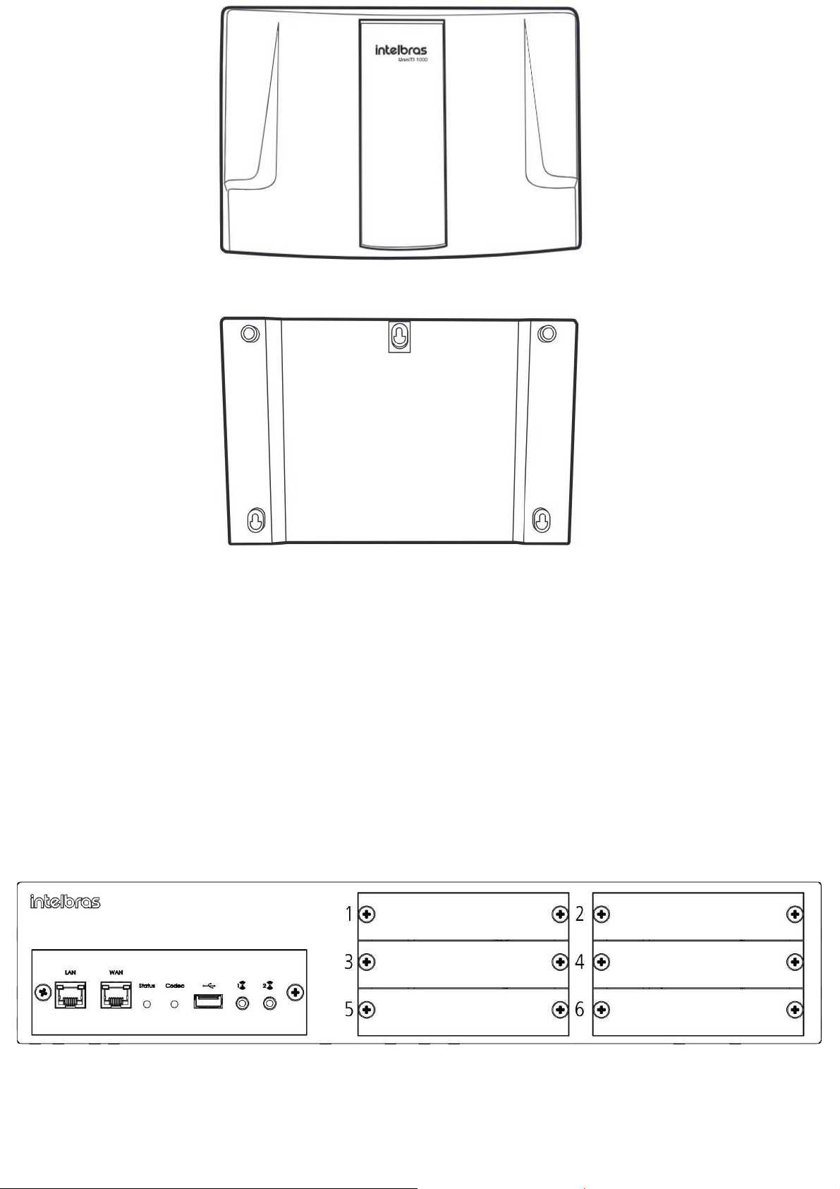
UnniTI 2000
The UnniTI 2000 consists of a CPU with embedded IP communication technology and 6 more slots for connecting the
interfaces: analog extensions, analog trunks, digital extensions, digital trunks (E1), GSM/3G trunks, mixed extensions (analog
and digital) and call recording. Interface E1 should be connected only in slot 1, the other interfaces in any position. The on-
off switch and power connector (operating range: 90~240 Vac) are on the back of the equipment. The following figures show
the front and back views of the product.
Front view
Rear view
If the UnniTI 2000 is set to factory default, the first time it is turned on with one or more cards attached, they will be
automatically recognized. Example: an E1 card was connected in position 1 and an analog extension card in position 2, when
it is connected the first time with these cards and with the factory default, the control panel will automatically recognize these
interfaces,E1 position 1 and analog extension position 2, after that, if any more cardis added, it will be necessary to configure
it in the slot to which it was connected. All control panel and user configuration settings are stored in flash memory and are
not lost in the event of a power outage.
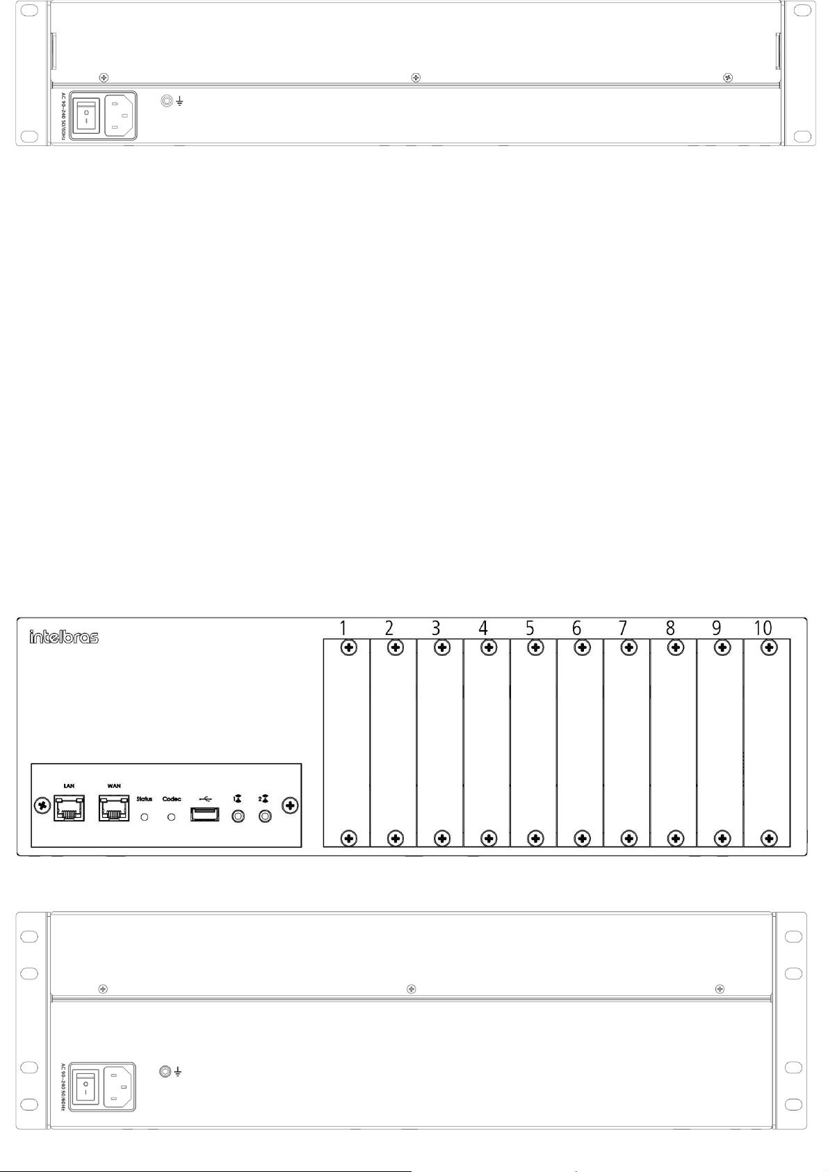
UnniTI 3000
The UnniTI 3000 consists of a CPU with embedded IP communication technology and 10 more slots for connecting the
interfaces: analog extensions, analog trunks, digital extensions, digital trunks (E1), GSM/3G trunks, mixed extensions (analog
and digital) and call recording. Interface E1 should be connected only in slot 1, the other interfaces in any position. On the
back of the product is the power connector (operating range: 90~240 Vac) and the on-off switch. The following figures show
the front and back views of the product.
Front view
Rear view

If the UnniTI 3000 is set to factory default, the first time it is turned on with one or more cards attached, they will be
automatically recognized. Example: an E1 card was connected in position 1 and an analog extension card in position 2, when
it is connected the first time with these cards and with the factory default, the control panel will automatically recognize these
interfaces,E1 position 1 and analog extension position 2, after that, if any more cardis added, it will be necessary to configure
it in the slot to which it was connected. All control panel and user configuration settings are stored in flash memory and are
not lost in the event of a power outage.
Electrical Protections
The power supply has protection against transients and oscillations in the electrical power grid. The branches and trunks
have protections against electrical transients.
Extension numbering
The factory default numberings are created from 2000 up to the number of extensions configured in UnniTI. E.g.: if there is
an extension card configured on the UnniTI 1000, the factory default numbering will be from 2000 to 2003, if configured on
the UnniTI 2000 and Unniti 3000 switchboards, the factory default numbering will be from 2000 to 2015. This numbering can
be changed.
Branch and trunk capacity
Type of
UnniTI 1000
Board/Interface
UnniTI 2000
UnniTI 3000
Extensions Up to 32 extensions
Analog
Up to 96 extensions
Up to 160 extensions
Digital Extensions IN
Up to 48 extensions1
Up to 48 extensions1
Up to 8 digital extensions1
and 24
Mixed Extensions Analog Extensions
Up to 24 digital extensions1
and 72
Analog Extensions
Up to 40 digital extensions1 and
120
Analog Extensions
IP Extensions Up to 250 extensions2
Up to 250 extensions2
Up to 250 extensions2
Trunks Up to 6 trunks
Analog
Up to 24 trunks
Up to 24 trunks
Digital Trunking Up to 30 channels
1E1
Up to 30 channels
Up to 30 channels
Digital Trunking IN
2E1
Up to 60 channels
Up to 60 channels
Trunks Up to 2 SIM cards
GSM/3G
Up to 24 SIM cards
Up to 24 SIM cards
IP Trunks Up to 50 trunks2
Up to 60 trunks2
Up to 60 trunks2

1TI 5000 model.
2With codec board 60 from version 21.06.29.
Maximum quantity of plates
Board/Interface Type
UnniTI 1000
UnniTI 2000
UnniTI 3000
Analog Extensions
8
6
10
Digital Extensions
IN
4
4
Mixed Extensions
8
6
10
Analog Trunks
3
3
3
1E1 Digital Trunks
1
1
1
2E1 Digital Trunks
IN
1
1
GSM/3G Trunks
1
3
3
Engraving board
1
1
1
Extensions coupled to analog trunks in the absence
of electrical power
In the absence of electricity, some analog lines are coupled to the analog branches, as shown in the following table:
Model Branch attached to the trunk in the absence of power
Last branch of slot 1 with the 1st trunk of slot 9
UnniTI 10001
Last extension of slot 2 with the 1st trunk of slot
10 Last extension of slot 3 with the 1st trunk of
slot 11
UnniTI 2000 Last branch of slot 2 with the 1st trunk of slot 6 or Last branch of slot 6 with the 1st trunk of slot 2
Last branch of slot 2 with the 1st trunk of slot 8 or Last branch of slot 8 with the 1st trunk of slot 2
UnniTI 3000 Last branch of slot 3 with the 1st trunk of slot 9 or Last branch of slot 9 with the 1st trunk of slot 3
Last branch of slot 4 with the 1st trunk of slot 10 or Last branch of slot 10 with the 1st trunk of slot 4
Slot 9/CN 25
Slot 10/CN 24
Slot 11/CN 15
1 If the last positions of the extensions are muted, check the configuration of the jumpers

W
i
t
h
o
u
t
J
1
6
a
n
d
J
1
7
p
l
a
t
e
c
l
o
s
e
d
W
i
t
h
J
1
6
and J17 plates open Without
J14 and J15 plate closed With
J14 and J15 plates open
Without J11 and J10 plate
closed

With open J11 and J10 plates
CPU
UnniTI 1000 CPU
The CPU board has the interfaces of LAN, WAN, USB, P2 Connector (AUX1) and SD microcard connections. You need to
remove the case cover to access them internally.
The following figure shows the inside of the CPU board.
Internal view of the UnniTI 1000 CPU
1 - Slot 1 to Slot 8: Connection of extension cards.
2 - USB connector for hardware key.
3 - MicroSD connector for memory card.
4 - P2 Connector: External Input/Music or Person Output/Search.
5 - Central grounding connector.
6 - Slot 9 through Slot 11: Connection of analog trunk cards.
7 - J17/J16, J15/J14 and J11/J10: Jumper for line coupling.

Slot Trunk Jumper
without plate J17/J16 Closed
9 with plate J17/J16 open
without plate J15/J14 Closed
10 with plate J15/J14 open
without plate J11/J10 Closed
11 with plate J11/J10 open
8 - Slot 12: E1 Digital Trunk Card Connection.
9 - OPC slot: GSM/3G trunk card connection.
10 - LAN network interface.
11- WAN network interface.
12 - Jumper Recover
13 - Connector for CODEC 10/60 Board.
14 - Jumper Reset
15 - Jumper Watch Dog
16 - Battery Jumper
17 - Power supply connector.
Interior view of UnniTI 1000 LEDs
If the last positions of the extensions are muted, check the jumper configuration

1 - AC Power LED.
2 - FPGA LED.
3 - Status LED.
4 - CDC LED –VoIP Codec.
5 - LED VoIP Status.
6 - ACT - WAN.
7 - LINK - WAN.
8 - ACT - LAN.
9 - LINK –LAN.
10 - SD Card Communication Status.
Power LED
Description
Demonstration
Lit
Central connected to the mains - AC
Extinct
Central not connected to the mains –AC
FPGA LED - Flashes once when powering on the
control panel
Description
Demonstration
Lit
Not configured
Extinct
Configured
LED de Status CPU Description Demonstration
Always lit Recovery Mode
Always Off Plant failure
Flashing too fast (15ms ON / 30ms OFF) Initializing
Fast flashing (50ms ON / 50ms OFF) Configuring
Moderate flashing (100ms ON / 100ms OFF) Waiting for System1
Slow flashing (300ms ON / 300ms OFF) Initialized Central
Flashing too slow (1000ms ON / 1000ms OFF) Corrupted flash images
flashing intermittently (500ms ON / 100ms OFF) Recovery attempt
1 If the LED indicates the status Waiting for system for more than 10 minutes and does not progress to the Central status
initialized, perform the procedure described in the Frequently Asked Questions section > Recover Startup ().
LED CDC –Codec VoIP Description Demonstration
Always lit Module Detected but Not Initialized
Always Off Module Not Detected
Fast flashing (100ms ON / 100ms OFF) Module Initializing:
Slow Flashing (300ms ON/300ms OFF) Initialized Module
Flashing flashing (1400ms ON / 100ms OFF) Module Initialization Failure
This manual suits for next models
1
Other Intelbras Telephone System manuals

Popular Telephone System manuals by other brands


Syscom Video
Syscom Video AV Series user guide

Lucent Technologies
Lucent Technologies R4.2 Administration

Toshiba
Toshiba Strata VI Series installation instructions

Aristel
Aristel DV-22 installation manual

Toshiba
Toshiba Strata CTX Attendant Console Quick reference guide

Panasonic
Panasonic KX-TSC14B Service manual


