Intelect 2778 User manual

Mobile Stim & Combo Therapy Systems
SERVICE MANUAL
© 2005 Encore Medical, L.P.
Model- 2777
Mobile Stim
Therapy System
Applies to Serial numbers 1000 and above
Model- 2778
Mobile Combo
Therapy System
Applies to Serial numbers 1000 and above

Intelect® Mobile Stim and Combo Therapy Systems
TABLE OF CONTENTS
FOREWORD . .. .. .. .. .. .. .. .. .. .. .. .. .. .. .. .. .. .. .. .. .. .. .. 1
1 SAFETY PRECAUTIONS .. .. .. .. .. .. .. .. .. .. .. .. .. .. .. 2
1.1 PRECAUTIONARY SYMBOL DEFINITIONS. .. 2
1.2 SAFETY PRECAUTIONS.. .. .. .. .. .. .. .. .. .. .. .. .. 2
2 THEORY OF OPERATION .. .. .. .. .. .. .. .. .. .. .. .. .. .. 5
2.1 OVERVIEW . .. .. .. .. .. .. .. .. .. .. .. .. .. .. .. .. .. .. .. .. 5
2.2 POWER SUPPLY CIRCUIT.. .. .. .. .. .. .. .. .. .. .. .. 5
2.3 CONTROL BOARD .. .. .. .. .. .. .. .. .. .. .. .. .. .. .. .. 5
2.4 STIM BOARDS. .. .. .. .. .. .. .. .. .. .. .. .. .. .. .. .. .. .. 5
2.5 ULTRASOUND BOARD AND APPLICATOR
COMBINATION SYSTEMS ONLY . .. .. .. .. .. .. 5
2.6 USER INTERFACE AND ACCESSORIES .. .. .. .. 5
2.7 NIMH BATTERY . .. .. .. .. .. .. .. .. .. .. .. .. .. .. .. .. .. 5
3 NOMENCLATURE . .. .. .. .. .. .. .. .. .. .. .. .. .. .. .. .. .. .. 6
3.1 COMPONENT AND CONTROLS .. .. .. .. .. .. .. .. 6
3.2 HARDWARE AND SOFTWARE
SYMBOL DEFINITIONS .. .. .. .. .. .. .. .. .. .. .. .. .. 8
4 SPECIFICATIONS .. .. .. .. .. .. .. .. .. .. .. .. .. .. .. .. .. .. .. 9
4.1 INTELECT MOBILE COMBO SYSTEM.. .. .. .. .. 9
4.2 INTELECT MOBILE STIM SYSTEM . .. .. .. .. .. 10
4.3 INTELECT ELECTROTHERAPY
WAVEFORM SPECIFICATIONS . .. .. .. .. .. .. .. 11
4.4 INTELECT MOBILE COMBO
ULTRASOUND SPECIFICATIONS .. .. .. .. .. .. 17
5 TROUBLESHOOTING. .. .. .. .. .. .. .. .. .. .. .. .. .. .. .. 18
5.1 INTELECT MOBILE STIM AND
COMBO ERROR MESSAGES. .. .. .. .. .. .. .. .. 18
5.2 INTELECT MOBILE STIM AND
COMBO SYSTEM TESTING .. .. .. .. .. .. .. .. .. 21
5.3 VISUAL INSPECTION . .. .. .. .. .. .. .. .. .. .. .. .. 22
5.4 LEAKAGE TESTS. .. .. .. .. .. .. .. .. .. .. .. .. .. .. .. 22
5.5 UNIT STARTUP AND FAN TESTING .. .. .. .. 22
5.6 ELECTRICAL STIMULATOR TEST
SYSTEM SETUP .. .. .. .. .. .. .. .. .. .. .. .. .. .. .. .. 23
5.7 VMS™ MODE TEST .. .. .. .. .. .. .. .. .. .. .. .. .. .. 23
5.8 INTERFERENTIAL MODE TEST.. .. .. .. .. .. .. 24
5.9 PREMODULATED MODE TEST.. .. .. .. .. .. .. 24
5.10 RUSSIAN MODE TEST .. .. .. .. .. .. .. .. .. .. .. .. 25
5.11 MICROCURRENT MODE TEST .. .. .. .. .. .. .. 26
5.12 HIGH VOLTAGE PULSED CURRENT
HVPC MODE TEST .. .. .. .. .. .. .. .. .. .. .. .. .. 27
5.13 ULTRASOUND TESTS. .. .. .. .. .. .. .. .. .. .. .. .. 28
5.14 ULTRASOUND APPLICATOR
IDENTIFICATION TEST . .. .. .. .. .. .. .. .. .. .. .. 28
5.15 ULTRASOUND APPLICATOR
OUTPUT TEST.. .. .. .. .. .. .. .. .. .. .. .. .. .. .. .. .. 29
5.16 ULTRASOUND DUTY CYCLE TEST . .. .. .. .. 30
5.17 COMBO OPERATION TEST .. .. .. .. .. .. .. .. .. 31
6 REMOVAL & REPLACEMENT.. .. .. .. .. .. .. .. .. .. .. 32
6.1 SEPARATING TOP & BOTTOM .. .. .. .. .. .. .. .. 32
6.2 THERAPY SYSTEM FAN .. .. .. .. .. .. .. .. .. .. .. .. 33
6.3 POWER SUPPLY .. .. .. .. .. .. .. .. .. .. .. .. .. .. .. .. . 34
6.4 CHANNEL 1 STIM BOARD.. .. .. .. .. .. .. .. .. .. . 36
6.5 CHANNEL 2 STIM BOARD.. .. .. .. .. .. .. .. .. .. ..37
6.6 ULTRASOUND BOARD
COMBO SYSTEMS ONLY . .. .. .. .. .. .. .. .. .. .. ..38
6.7 CONTROL BOARD ASSEMBLY .. .. .. .. .. .. .. ..39
6.8 KEYMAT ASSEMBLY AND ON/OFF
BUTTON KEYMAT .. .. .. .. .. .. .. .. .. .. .. .. .. .. .. 40
7 GENERAL MAINTENANCE .. .. .. .. .. .. .. .. .. .. .. .. 41
7.1 CLEANING THE SYSTEM .. .. .. .. .. .. .. .. .. .. .. 41
7.2 CALIBRATION REQUIREMENTS.. .. .. .. .. .. .. 41
7.3 FIELD SERVICE .. .. .. .. .. .. .. .. .. .. .. .. .. .. .. .. .. 41
7.4 FACTORY SERVICE.. .. .. .. .. .. .. .. .. .. .. .. .. .. .. 41
8 ULTRASOUND APPLICATOR CALIBRATION . .. 42
8.1 GENERAL PROCEDURES .. .. .. .. .. .. .. .. .. .. .. 42
9 PARTS . .. .. .. .. .. .. .. .. .. .. .. .. .. .. .. .. .. .. .. .. .. .. .. .. 43
10 SCHEMATICS. .. .. .. .. .. .. .. .. .. .. .. .. .. .. .. .. .. .. .. 51
11 WARRANTY. .. .. .. .. .. .. .. .. .. .. .. .. .. .. .. .. .. .. .. .. 68

1
Intelect® Mobile Stim and Combo Therapy Systems
Read, understand, and follow the Safety Precautions and all other information contained in this
manual.
This manual contains the necessary safety and field service information for those field service
technicians, certified by Chattanooga Group, to perform field service on the Intelect Mobile Stim or
Combo Therapy Systems.
At the time of publication, the information contained herein was current and up-to-date. However,
due to continual technological improvements and increased clinical knowledge in the field of
electrotherapy, as well as Chattanooga Group’s policy of continual improvement, Chattanooga
Group reserves the right to make periodic changes and improvements to their equipment and
documentation without any obligation on the part of Chattanooga Group.
FOREWORD
©2005 Encore Medical Corporation or its affiliates, Austin, Texas, USA. Any use of editorial, pictorial or layout composition of this publication without express written consent from the Chattanooga Group of Encore
Medical, L.P. is strictly prohibited. This publication was written, illustrated and prepared for print by the Chattanooga Group of Encore Medical, L.P.
2
Intelect® Mobile Stim and Combo Therapy Systems
1.1 PRECAUTIONARY SYMBOL DEFINITIONS
The precautionary instructions found in this manual are indicated by specific
symbols. Understand these symbols and their definitions before operating or
servicing this equipment. The definitions of these symbols are as follows:
A. CAUTION
Text with a“CAUTION”indicator will explain possible safety infractions
that have the potential to cause minor to moderate injury or damage
to equipment.
B. WARNING
Text with a“WARNING”indicator will explain possible safety
infractions that will potentially cause serious injury and equipment
damage.
C. DANGER
Text with a“DANGER”indicator will explain possible safety infractions
that are imminently hazardous situations that would result in death
or serious injury.
D. DANGEROUS VOLTAGE
Text with a“Dangerous Voltage”indicator serves to inform the user
of possible hazards resulting in the electrical charge delivered to the
patient in certain treatment configurations ofTENS waveforms.
E. CORROSIVE HAZARD NIMH BATTERY
Text with a“Corrosive Hazard”indicator will explain possible safety
infractions if the chemical components of this product are exposed to
air, skin, or other materials.
F. NOTE:
Throughout this manual“NOTE”may be found.These Notes
are helpful information to aid in the particular area or function being
described.
1.2 SAFETY PRECAUTIONS
Read, understand, and follow all safety precautions found in this manual.
Below are general safety precautions that must be read and understood before
attempting any service techniques on these systems.
Read, understand, and practice the precautionary and operating instructions.
Know the limitations and hazards associated with using any electrical
stimulation or ultrasound device. Observe the precautionary and operational
decals placed on the unit.
DO NOT operate the Intelect Stim or Combo System when connected to any
unit other than Chattanooga Group devices. Do not operate the unit in an
environment of short-waveform diathermy use.
The Ultrasound modality should be routinely checked before each use to
determine that all controls function normally; especially that the intensity
control properly adjusts the intensity of the ultrasonic power output in a
stable manner. Also, determine that the treatment time control actually
terminates ultrasonic power output when the timer reaches zero.
Use of controls or adjustments or performance of procedures other than
those specified herein may result in hazardous exposure to ultrasonic energy.
DO NOT use sharp objects such as a pencil point or ballpoint pen to operate
the buttons on the control panel as damage may result.
Operate, transport, and store this unit in temperatures between 59 °F and
104 °F (15 °C and 40 °C), with Relative Humidity ranging from 30%-60%.
Inappropriate handling of, and subjecting the ultrasound applicator to
physical abuse, may adversely affect its characteristics.
Inspect Sound Head and Applicator handle for cracks, which may allow the
ingress of conductive fluid before each use.
Inspect all cables, leads, and associated connectors before each use.
Never disconnect Applicator Cable, Lead Wires, Patient Switches, and Mains
Power Cord from the system by pulling the cable or wire. Pulling cable or
wire may cause system or accessory damage and result in injury to patient
and personnel.
•
•
•
•
•
•
•
•
•
•
1 SAFETY PRECAUTIONS
3
Intelect® Mobile Stim and Combo Therapy Systems
1 SAFETY PRECAUTIONS
These devices are restricted to sale by, or on the order of, a
physician or licensed practitioner. This device should be used
only under the continued supervision of a physician or licensed
practitioner.
For continued protection against fire hazard, replace fuses
only with ones of the same type and rating.
Make certain the unit is electrically grounded by connecting
only to a grounded electrical service receptacle conforming to
the applicable national and local electrical codes.
Care must be taken when operating this equipment around
other equipment. Potential electromagnetic or other
interference could occur to this or to the other equipment. Try
to minimize this interference by not using other equipment in
conjunction with it.
The safety of TENS waveforms for use during pregnancy or
birth has not been established.
TENS is not effective for pain of central origin. This includes
headache.
TENS should be used only under the continued supervision of
a physician or licensed practitioner.
TENS waveforms have no curative value.
TENS is a symptomatic treatment, and as such, suppresses the
sensation of pain which would otherwise serve as a protective
mechanism.
The user must keep the device out of the reach of children.
Electronic monitoring equipment (such as ECG monitors and
ECG alarms) may not operate properly when TENS stimulation
is in use.
Powered muscle stimulators should be used only with
the leads and electrodes recommended for use by the
manufacturer.
In the event that an Error message or Warning appears
beginning with a 2 or 3, immediately stop all use of the
system and contact the dealer or Chattanooga Group for
service. Errors and Warnings in these categories indicate an
internal problem with the system that must be tested by
Chattanooga Group or a Field Service Technician certified by
Chattanooga Group before any further operation or use of the
system. Use of a system that indicates an Error or Warning in
these categories may pose a risk of injury to the patient, user
or cause extensive internal damage to the system.
Use of controls or adjustments or performance of procedures
other than those specified herein may result in hazardous
exposure to ultrasonic energy.
Before administering any treatment to a patient you should
become acquainted with the operating procedures for
each mode of treatment available, as well as the indications,
contraindications, warnings, and precautions. Consult other
resources for additional information regarding the application
of Electrotherapy and Ultrasound.
To prevent electrical shock, disconnect the unit from
the power source before attempting any maintenance
procedures.
Keep electrodes separated during treatment. Electrodes in
contact with each other could result in improper stimulation
or skin burns.
Long term effects of chronic electrical stimulation are
unknown.
Stimulation should not be applied over the anterior neck
or mouth. Severe spasm of the laryngeal and pharyngeal
muscles may occur and the contractions may be strong
enough to close the airway or cause difficulty in breathing.
•
•
•
•
•
•
•
•
•
•
•
•
•
•
•
•
•
•
•
Stimulation should not be applied transthoracically in that
the introduction of electrical current into the heart may cause
cardiac arrhythmia.
Stimulation should not be applied over swollen, infected,
and inflamed areas or skin eruptions, (e.g., phlebitis,
thrombophlebitis, varicose veins, etc.).
Stimulation should not be applied over, or in proximity to,
cancerous lesions.
Output current density is related to electrode size. Improper
application may result in patient injury. If any question arises
as to the proper electrode size, consult a licensed practitioner
prior to therapy.
Unplug the unit from the power source before attempting
removal or replacement procedures to prevent electrical
shock.
Use only Degassed Water in Power Meter for testing Ultrasound
Applicators. Use of other types of water will cause false test
results. Refer to page 21 for Degassed Water Recipes.
Do not aerate water when filling Power Meter.
Unit failing Dielectric Withstand Test or Leakage Test could
indicate serious internal problems! Do not place unit back into
service! Send unit to factory for repair! Do not attempt to repair.
•
•
•
•
•
•
•
•
1.2 SAFETY PRECAUTIONS (continued)

4
Intelect® Mobile Stim and Combo Therapy Systems
1 SAFETY PRECAUTIONS
Stimulus delivered by the TENS waveforms of this
device, in certain configurations, will deliver a charge of
25 microcoulombs (μC) or greater per pulse and may
be sufficient to cause electrocution. Electrical current
of this magnitude must not flow through the thorax
because it may cause a cardiac arrhythmia.
Patients with an implanted neurostimulation device
must not be treated with or be in close proximity to
any shortwave diathermy, microwave diathermy,
therapeutic ultrasound diathermy, or laser diathermy
anywhere on their body. Energy from diathermy
(shortwave, microwave, ultrasound, and laser) can be
transferred through the implanted neurostimulation
system, can cause tissue damage, and can result in
severe injury or death. Injury, damage, or death can
occur during diathermy therapy even if the implanted
neurostimulation system is turned “off.”
1.2 SAFETY PRECAUTIONS (continued)

5
Intelect® Mobile Stim and Combo Therapy Systems
2.1 OVERVIEW
The Intelect Mobile Therapy Systems are comprised of several PC board assemblies housed within a common
enclosure. These assemblies each support a distinct function in the product. The basic elements are User
Interface, Control Board, Stim Boards, Ultrasound Board (Combo only), Ultrasound Applicator (Combo only),
and Power Supply Circuits.
2.2 POWER SUPPLY CIRCUIT
A universal 75 Watt input power supply provides each system with the required 24 volts DC. The supply is
connected to the mains at all times when the Mains Power Cord is attached and plugged into an outlet
supplying 100 - 240 VAC. The 24 V supply is regulated locally at each PC board as required.
2.3 CONTROL BOARD
The Control Board serves just as its name implies. It controls the operation of the Stim Boards, Ultrasound
Board, User Interface, and Accessories. The Control Board communicates to the Stim Boards and Ultrasound
Board through a proprietary bus. The Control Board drives the display. The Control Board reads the menu
buttons. The Control Board also reads the amplitude and the Contrast Control on the systems. Sound output
is generated by the Control Board and routed to an internal speaker.
2.4 STIM BOARDS
The Stim Boards create all muscle stimulation output. Communication to the Stim Boards is via a
proprietary bus. A Processor on each Stim Board acts on messages passed to it by the Control Board
to set up waveforms and adjust output amplitude. Information can likewise be passed from each
Stim Board back to the Control Board for monitoring current, etc. If a Stim Board does not respond as
expected to a command from the Control Board, output is stopped and an Error Message is generated.
2.5 ULTRASOUND BOARD AND APPLICATOR COMBINATION SYSTEMS ONLY
The Ultrasound Board generates the 1 or 3.3 MHz output to drive the Sound Head of the Applicator. The
Ultrasound Board is accessed through the proprietary bus by the Control Board. It can provide current
and voltage information about the ultrasound output of the board. The calibration data for the Sound Head
is passed through the Ultrasound Board from the Applicator to the Control Board. By storing the calibration
data in the Applicator, there is no calibration necessary for the Ultrasound Board and any
calibrated Chattanooga Group Intelect Advanced or Intelect Mobile Ultrasound Applicator can be connected
and operated to provide accurate coupling and output.
2.6 USER INTERFACE AND ACCESSORIES
The LCD display panel provides the operator visible feedback in the way of menu choices. Pressing the
User Interface buttons makes selections from the menus. The Control Board interprets these user inputs and
responds accordingly. Audible feedback is given for such events as key presses and end of treatment.
2.7 NIMH BATTERY
The NiMH Battery Module incorporates a Nickel Metal Hydride (NiMH) Battery Pack and a PC Board. The
PC Board monitors the Battery Charge Level. The Battery Pack supplies the required 24 VDC to the system
which is then distributed to the respective PCB’s through the Universal Power Supply. The Battery
Pack is interfaced with the system via a Wire Harness that facilitates communication with the Control
Board and delivery of power to an Electrotherapy or Combination Therapy System. When the Therapy
System is connected to a Mains Power Supply via the Mains Power Cord, the NiMH Battery Pack will charge.
Once the Battery Pack is fully charged, the software will stop the charging process, eliminating the possibility
of overcharging. Battery power is used only when the Therapy System is not connected to a Mains Power
Supply.
2 THEORY OF OPERATION

6
Intelect® Mobile Stim and Combo Therapy Systems
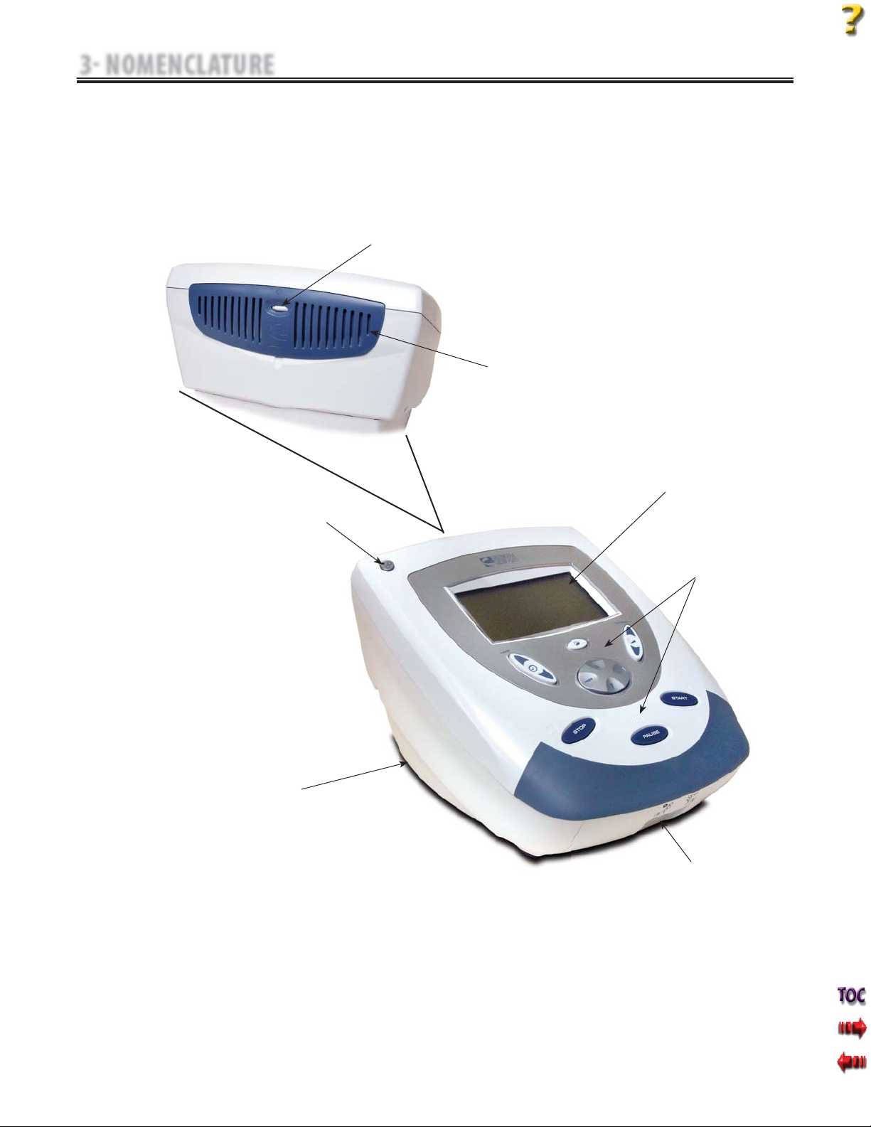
A. Intelect Mobile Combo System
The nomenclature graphics below, Figure 3.1, indicate the general
locations of the exterior components of theTwo Channel Intelect
Mobile Combo System.
Know the components and their functions before performing any
operation of or service to the Intelect Mobile Combo System.
FIGURE 3.1
3 NOMENCLATURE
3.1 COMPONENT AND CONTROLS
FAN VENT
CONTRAST
CONTROL
LCD
USER INTERFACE
ULTRASOUND
APPLICATOR
PLYNTH
ULTRASOUND
RECEPTACLE
ELECTROTHERAPY
LEAD WIRE
RECEPTACLES
ON/OFF
POWER
SWITCH
7
Intelect® Mobile Stim and Combo Therapy Systems
B. Intelect Mobile Stim System
The nomenclature graphics below, Figure 3.2, indicate the general
locations of the exterior components of theTwo Channel Intelect
Mobile Electrotherapy System.
Know the components and their functions before performing any
operation of or service to the Intelect Mobile Stim system.
FIGURE 3.2
3 NOMENCLATURE
3.1 COMPONENT AND CONTROLS LOCATION (continued)
FAN VENT
CONTRAST
CONTROL
LCD
USER INTERFACE
PLYNTH
ELECTROTHERAPY
LEAD WIRE
RECEPTACLES
ON/OFF
POWER
SWITCH

8
Intelect® Mobile Stim and Combo Therapy Systems
The symbols below are found on the system as well as within the
software. These symbols are defined for the purpose of recognition and
functionality when operating or performing service on the Intelect
Mobile Combo or Stim Systems.
Know the symbols and their definitions before performing
any operation of or service to the Intelect Mobile Combo or Stim
Systems.
ON/OFF
SWITCH
DATA
PORT
STOP
TREATMENT
PAUSE
TREATMENT
START
TREATMENT
A. Intelect Mobile Combo and Stim Therapy System Hardware Symbols
CHANNEL 1
LEAD WIRES
CHANNEL 2
LEAD WIRES
ULTRASOUND
APPLICATOR
CLINICAL
RESOURCES
BACK
CONTRAST CONTROL
INCREASE
DECREASE
CHARGE LEVEL
BATTERY
CHARGING
3 NOMENCLATURE
3.2 HARDWARE AND SOFTWARE SYMBOL DEFINITIONS
TREATMENT TIME
INTENSITY
PARAMETER DISPLAY/ENTER
DOWN ARROW
UP ARROW
9
Intelect® Mobile Stim and Combo Therapy Systems
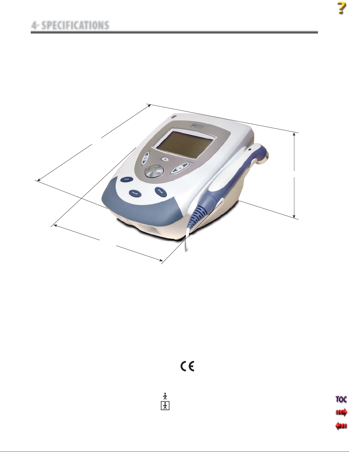
Figure 4.1 below provides physical details of the Intelect Mobile Combo.
This section also provides waveform specifications to aid in
troubleshooting.
Refer to this section when performing troubleshooting,
replacement, and repair of the Intelect Mobile Combo System.
A. Intelect Mobile Combination Therapy System Physical Specifications
Dimensions
Width.. .. .. .. .. .. .. .. .. .. .. .. .. .. .. .. .. .. .. .. .. .. .. .. .. .. .. .. ..25.7 cm (10.125 in)
Height. .. .. .. .. .. .. .. .. .. .. .. .. .. .. .. .. .. .. .. .. .. .. .. .. .. .. .. .. 18.4 cm (7.250 in)
Depth.. .. .. .. .. .. .. .. .. .. .. .. .. .. .. .. .. .. .. .. .. .. .. .. .. .. .. .. .. .. 29.2 cm (11.5 in)
Weight
Standard Weight (with base) .. .. .. .. .. .. .. .. .. .. .. .. .. .. .. .. .. .. 2.3 kg (5.07 lb)
Battery Pack. .. .. .. .. .. .. .. .. .. .. .. .. .. .. .. .. .. .. .. .. .. .. .. .. .. .. . 0.85 kg (1.87 lb)
Power
Input. .. .. .. .. .. .. .. .. .. .. .. .. .. .. .. . 100 - 240 VAC, 1.0 A, 50/60 Hz 100 W Max
Output. .. .. .. .. .. .. .. .. .. .. .. .. .. .. .. .. .. .. .. .. .. .. .. .. .. .. .. .. .. .. +24 V, 3.125 A
Fuses .. .. .. .. .. .. .. .. .. .. .. .. .. .. .. .. .. .. 3.15 A Time Lag (not user serviceable)
Electrical Class .. .. .. .. .. .. .. .. .. .. .. .. .. .. .. .. .. .. .. .. .. .. .. .. .. .. .. .. .. .. .. CLASS I
Electrical Type
UltrasoundTYPE B .. .. .. .. .. .. .. .. .. .. .. .. .. .. .. .. .. .. .. .. .. .. .. .. .. .. .. .. .. .. .
Electrotherapy TYPE BF. .. .. .. .. .. .. .. .. .. .. .. .. .. .. .. .. .. .. .. .. .. .. .. .. .. .. .. .
Battery Type. .. .. .. .. .. .. .. .. .. .. .. .. .. .. .. .. .. .. .. .. Nickel Metal Hydride (NiMH)
(1.2 V x 20 size AA)
Operating Environment
Temperature .. .. .. .. .. .. .. .. .. .. .. .. .. .. .. .. .. .. .. .. .. .. Between 15° C and 40° C
(59° F and 104° F)
Relative Humidity .. .. .. .. .. .. .. .. .. .. .. .. .. .. .. .. .. .. .. .. .. .. .. .. .. .. .. 30%-60%
Atmospheric Pressure .. .. .. .. .. .. .. .. .. .. .. .. .. .. .. .. .. .. .. .. .. .. . 950-1,050 h Pa
Complies with:
UL/IEC/EN 60601-1
IEC/EN 60601-1-2
IEC 60601-2-10
IEC 60601-2-5
FIGURE 4.1
4 SPECIFICATIONS
0413
4.1 INTELECT MOBILE COMBO SYSTEM
WIDTH
WIDTH
HEIGHT
HEIGHT
DEPTH
DEPTH

10
Intelect® Mobile Stim and Combo Therapy Systems
Figure 4.2 below provides the physical details of the Intelect
Mobile Stim.This section also provides waveform specifications to aid in
troubleshooting.
Refer to this section when performing troubleshooting,
replacement, and repair of the Intelect Mobile Stim .
A. Intelect Mobile Stim Therapy System Physical Specifications
Dimensions
Width.. .. .. .. .. .. .. .. .. .. .. .. .. .. .. .. .. .. .. .. .. .. .. .. .. .. .. .. ..25.7 cm (10.125 in)
Height. .. .. .. .. .. .. .. .. .. .. .. .. .. .. .. .. .. .. .. .. .. .. .. .. .. .. .. .. 16.8 cm (6.625 in)
Depth.. .. .. .. .. .. .. .. .. .. .. .. .. .. .. .. .. .. .. .. .. .. .. .. .. .. .. .. .. .. 29.2 cm (11.5 in)
Weight
Standard Weight (with base) .. .. .. .. .. .. .. .. .. .. .. .. .. .. .. .. .. .. 2.3 kg (5.07 lb)
Battery Pack. .. .. .. .. .. .. .. .. .. .. .. .. .. .. .. .. .. .. .. .. .. .. .. .. .. .. . 0.85 kg (1.87 lb)
Power
Input. .. .. .. .. .. .. .. .. .. .. .. .. .. .. .. . 100 - 240 VAC, 1.0 A, 50/60 Hz 100 W Max
Output. .. .. .. .. .. .. .. .. .. .. .. .. .. .. .. .. .. .. .. .. .. .. .. .. .. .. .. .. .. .. +24 V, 3.125 A
Fuses .. .. .. .. .. .. .. .. .. .. .. .. .. .. .. .. .. .. 3.15 A Time Lag (not user serviceable)
Electrical Class .. .. .. .. .. .. .. .. .. .. .. .. .. .. .. .. .. .. .. .. .. .. .. .. .. .. .. .. .. .. .. CLASS I
Electrical Type
Electrotherapy TYPE BF. .. .. .. .. .. .. .. .. .. .. .. .. .. .. .. .. .. .. .. .. .. .. .. .. .. .. .. .
Battery Type. .. .. .. .. .. .. .. .. .. .. .. .. .. .. .. .. .. .. .. .. Nickel Metal Hydride (NiMH)
(1.2 V x 20 size AA)
Operating Environment
Temperature .. .. .. .. .. .. .. .. .. .. .. .. .. .. .. .. .. .. .. .. .. .. Between 15° C and 40° C
(59° F and 104° F)
Relative Humidity .. .. .. .. .. .. .. .. .. .. .. .. .. .. .. .. .. .. .. .. .. .. .. .. .. .. .. 30%-60%
Atmospheric Pressure .. .. .. .. .. .. .. .. .. .. .. .. .. .. .. .. .. .. .. .. .. .. . 950-1,050 h Pa
Complies with:
UL/IEC/EN 60601-1
IEC/EN 60601-1-2
IEC 60601-2-10
IEC 60601-2-5
FIGURE 4.2
4 SPECIFICATIONS
0413
4.2 INTELECT MOBILE STIM SYSTEM
WIDTH
WIDTH
HEIGHT
HEIGHT
DEPTH
DEPTH

11
Intelect® Mobile Stim and Combo Therapy Systems
A. IFC (Interferential) Traditional (4 Pole)- Figure 4.3
Interferential Current is a medium frequency waveform. Current is
distributed from two channels (four electrodes). The currents cross
in the body within the area being treated. The two currents interfere
with each other at this crossing point, resulting in a modulation
of the intensity (the current intensity increases and decreases at a
regular frequency).
Output Mode. . . . . . . . . . . . . . . . . . . . . . . . . . . . . . . . . . . . . . . Electrodes
Output Intensity . . . . . . . . . . . . . . . . . . . . . . . . . . . . . . . . . . . . 0-100 mA
Carrier Frequency . . . . . . . . . . . . . . . . . . . . . . . . . . . . . 2,000-10,000 Hz
Beat Frequency . . . . . . . . . . . . . . . . . . . . . . . . . . . . . . . . . . . . . .1-200 Hz
Sweep Time . . . . . . . . . . . . . . . . . . . . . . . . . . . . . . . . . . . . . . . 15 seconds
Sweep Low Beat Frequency. . . . . . . . . . . . . . . . . . . . . . . . . . . .1-200 Hz
Sweep High Beat Frequency . . . . . . . . . . . . . . . . . . . . . . . . . . . 1-200 Hz
Scan Percentage . . . . . . . . . . . . . . . . . . . . . . . . .Static, 40%, and 100%
Treatment Time . . . . . . . . . . . . . . . . . . . . . . . . . . . . . . . . . . 1-60 Minutes
B. TENS- Asymmetrical Biphasic- Figure 4.4
The Asymmetrical Biphasic waveform has a short pulse duration. It
is capable of strong stimulation of the nerve fibers in the skin as well
as of muscle tissue.This waveform is often used in TENS devices.
Because of its short pulse, the patient typically tolerates the current
well, even at relatively high intensities.
Output Mode. . . . . . . . . . . . . . . . . . . . . . . . . . . . . . . . . . . . . . . Electrodes
Output Intensity . . . . . . . . . . . . . . . . . . . . . . . . . . . . . . . . . . . . 0-110 mA
Phase Duration . . . . . . . . . . . . . . . . . . . . . . . . . . . . . . . . . 20-1,000 μsec
Frequency. . . . . . . . . . . . . . . . . . . . . . . . . . . . . . . . . . . . . . . . . . .1-250 Hz
Mode Selection. . . . . . . . . . . . . . . . . . . . . . . . . . . . . . . . . . . . . CC or CV*
Burst Frequency. . . . . . . . . . . . . . . . . . . . . . . . . . . . . . . . . . . . . . 0-25 bps
Frequency Modulation. . . . . . . . . . . . . . . . . . . . . . . . . . . . . . . .0-250 Hz
Amplitude Modulation. . . . . . . . . . . Off, 40%, 60%, 80%, and 100%
Treatment Time . . . . . . . . . . . . . . . . . . . . . . . . . . . . . . . . . . 1-60 Minutes
The specifications found in this section provide the necessary waveform
specifications to aid in troubleshooting. A waveform graphic from an
oscilloscope is also provided for clarification.
Refer to this section when performing troubleshooting, replacement, and
repair of the Intelect Mobile Stim and Combo Systems.
NOTE:
All waveforms except HighVoltage Pulsed Current (HVPC) of the Intelect
Mobile Therapy System have been designed with a 200 mA current limit.
VMS™, and all TENS waveform output intensities are measured, specified, and
listed to peak, not peak to peak.
All Waveforms are available on all channels.
FIGURE 4.3
FIGURE 4.4
*CC= Constant Current
CV= Constant Voltage
4.3 INTELECT ELECTROTHERAPY WAVEFORM SPECIFICATIONS
Stimulus delivered by the TENS waveforms of this device, in
certain configurations, will deliver a charge of 25 microcoulombs
(μC) or greater per pulse and may be sufficient to cause
electrocution. Electrical current of this magnitude must not flow
through the thorax because it may cause a cardiac arrhythmia.
4 SPECIFICATIONS

12
Intelect® Mobile Stim and Combo Therapy Systems
C. TENS- Symmetrical Biphasic- Figure 4.5
The Symmetrical Biphasic waveform has a short pulse duration and
is capable of strong stimulation of nerve fibers in the skin and in
muscle.This waveform is often used in portable muscle stimulation
units and some TENS devices. Because of its short pulse duration,
the patient typically tolerates the current well, even at relatively high
intensities.
Output Mode. . . . . . . . . . . . . . . . . . . . . . . . . . . . . . . . . . . . . . . Electrodes
Output Intensity . . . . . . . . . . . . . . . . . . . . . . . . . . . . . . . . . . . . 0-100 mA
Phase Duration . . . . . . . . . . . . . . . . . . . . . . . . . . . . . . . . . 20-1,000 μsec
Frequency. . . . . . . . . . . . . . . . . . . . . . . . . . . . . . . . . . . . . . . . . . .1-250 Hz
Mode Selection. . . . . . . . . . . . . . . . . . . . . . . . . . . . . . . . . . . . . CC or CV*
Burst Frequency. . . . . . . . . . . . . . . . . . . . . . . . . . . . . . . . . . . . . . 0-25 bps
Frequency Modulation. . . . . . . . . . . . . . . . . . . . . . . . . . . . . . . .0-250 Hz
Amplitude Modulation. . . . . . . . . . . Off, 40%, 60%, 80%, and 100%
Treatment Time . . . . . . . . . . . . . . . . . . . . . . . . . . . . . . . . . . 1-60 Minutes
D. High Voltage Pulsed Current (HVPC)- Figure 4.6
The HighVoltage Pulsed Current (HVPC) has a very brief pulse
duration characterized by 2 distinct peaks delivered at high voltage.
The waveform is monophasic (current flows in one direction only).
The high voltage causes a decreased skin resistance, making the
current comfortable and easy to tolerate.
Output Mode . . . . . . . . . . . . . . . . . . . . . . . . . . . . . . . Electrodes or Probe
Output Intensity. . . . . . . . . . . . . . . . . . . . . . . . . . . . . . . . . . . . . . . 0-500V
Polarity . . . . . . . . . . . . . . . . . . . . . . . . . . . . . . . . . . . .Positive or Negative
Ramp. . . . . . . . . . . . . . . .0.5 seconds, 1 seconds, 2 seconds, 5 seconds
Display. . . . . . . . . . . . . . . . . . . . . . . . . . . . . . . . . . . . Peak Current or Volts
Sweep . . . . . . . . . . . . . . Continuous, 80/120 pps, 1/120 pps, 1/10 pps
Frequency . . . . . . . . . . . . . . . . . . . . . . . . . . . . . . . . . . . . . . . . . .10-120 Hz
Cycle Time . . . . . . . . . . . . . . . . . . . . . . . 5/5, 4/12, 10/10, 10/20, 10/30,
10/50, and Continuous
Treatment Time. . . . . . . . . . . . . . . . . . . . . . . . . . . . . . . . . . . 1-99 Minutes
E. VMS™- Figure 4.7
VMS is a symmetrical biphasic waveform with a 100 μsec interphase
interval. Because the pulse is relatively short, the waveform has
a low skin load, making it suitable for applications requiring high
intensities such as in muscle strengthening protocols.
Output Mode. . . . . . . . . . . . . . . . . . . . . . . . . . . . . . . . . . . . . . . Electrodes
Output Intensity . . . . . . . . . . . . . . . . . . . . . . . . . . . . . . . . . . . . 0-200 mA
Channel Mode. . . . . . . . . . . . . . . . . . . . Single, Reciprocal, Co-Contract
Phase Duration . . . . . . . . . . . . . . . . . . . . . . . . . . . . . . . . . . 20-1000 μsec
Mode Selection. . . . . . . . . . . . . . . . . . . . . . . . . . . . . . . . . . . . . CC or CV*
Anti-Fatigue. . . . . . . . . . . . . . . . . . . . . . . . . . . . . . . . . . . . . . . . . Off or On
Set Intensity. . .Individual Channel Intensity Setting in Reciprocal and
Co-Contract modes
Cycle Time . . . . . . . . . . . . . . . . . . . . . . . . Continuous, 5/5, 4/12, 10/10,
10/20, 10/30, 10/50
Frequency. . . . . . . . . . . . . . . . . . . . . . . . . . . . . . . . . . . . . . . . . 1-200 pps
Ramp . . . . . . . . . . . . . . .0.5 seconds, 1 seconds, 2 seconds, 5 seconds
Treatment Time . . . . . . . . . . . . . . . . . . . . . . . . . . . . . . . . . . 1-60 Minutes
FIGURE 4.5
FIGURE 4.6
*CC= Constant Current
CV= Constant Voltage
FIGURE 4.7
4 SPECIFICATIONS
4.3 INTELECT ELECTROTHERAPY WAVEFORM SPECIFICATIONS (continued)
13
Intelect® Mobile Stim and Combo Therapy Systems
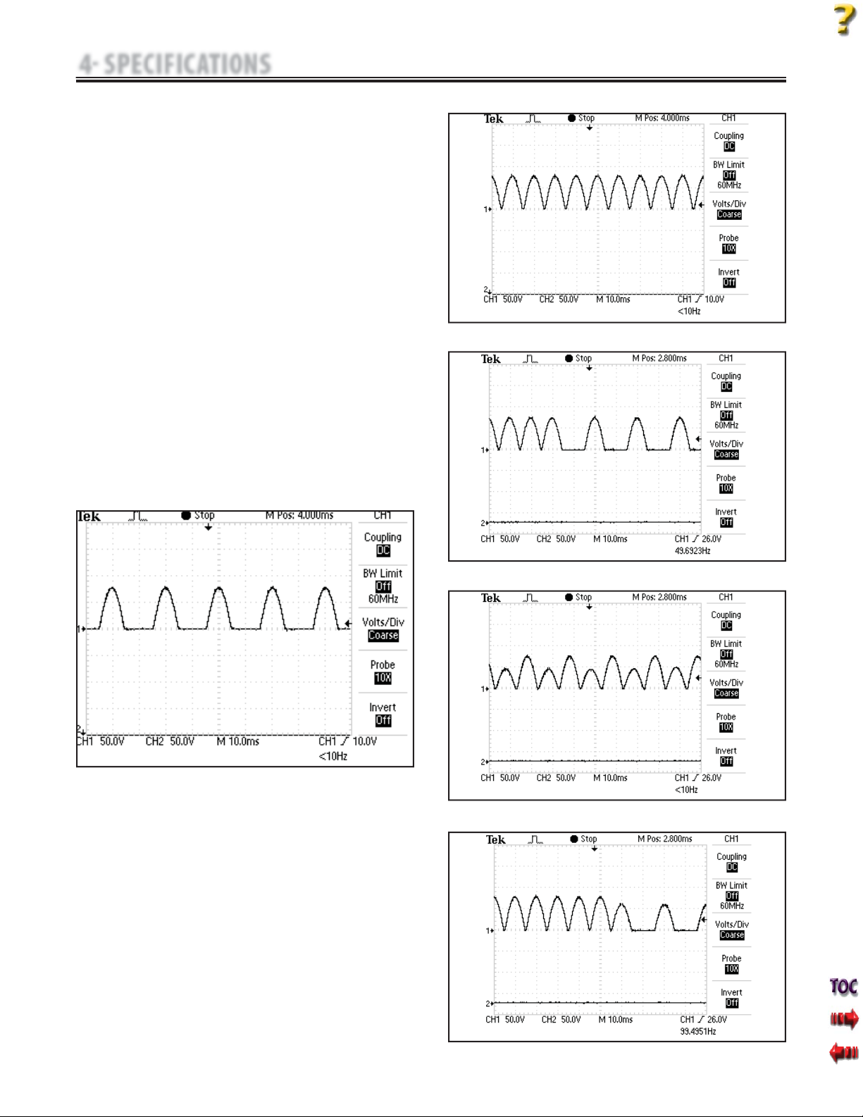
F. Diadynamic Waveforms- Figures 4.8 - 4.12
The Diadynamic waveforms are rectified alternating currents.The
alternating current is modified (rectified) to allow the current to flow
in one direction only.
Output Mode. . . . . . . . . . . . . . . . . . . . . . . . . . . . . . . . . . . . . . . . Electrodes
Output Intensity . . . . . . . . . . . . . . . . . . . . . . . . . . . . . . . . . . . . . . 0-80 mA
Treatment Time. . . . . . . . . . . . . . . . . . . . . . . . . . . . . . . . . . . 1-60 Minutes
MF: (Monophasé Fixe)- Figure 4.8
Frequency of 50 Hz: phase duration of 10 ms followed by a pause of
10 ms.
DF: (Diphasé Fixe)- Figure 4.9
Frequency of 100 Hz: phase duration of 10 ms followed immediately
by another identical phase of 10 ms.
CP: Modulé en Courtes Périodes- Figure 4.10
1 second of MF followed abruptly by 1 second of DF.
LP: (Modulé en Longues Périodes)- Figure 4.11
Rhythmical fluctuation between 2 MF currents.
CP-iso: (Courtes Periodes Isodynamic)- Figure 4.12
A combination of MF and DF waveforms.
FIGURE 4.9
*CC= Constant Current
CV= Constant Voltage
FIGURE 4.8
FIGURE 4.10
FIGURE 4.11
FIGURE 4.12
4 SPECIFICATIONS
4.3 INTELECT ELECTROTHERAPY WAVEFORM SPECIFICATIONS (continued)
14
Intelect® Mobile Stim and Combo Therapy Systems
G. IFC (Interferential) Premodulated (2p)-
Figure 4.13
Premodulated Current is a medium frequency waveform. Current is
distributed from one channel (two electrodes). The current intensity
is modulated: it increases and decreases at a regular frequency (the
Amplitude Modulation Frequency).
Output Mode . . . . . . . . . . . . . . . . . . . . . . . . . . . . . . . . . . . . . . . Electrodes
Output Intensity. . . . . . . . . . . . . . . . . . . . . . . . . . . . . . . . . . . . . 0-100 mA
Carrier Frequency . . . . . . . . . . . . . . . . . . . . . . . . . . . . . . 2,000-10,000 Hz
Beat Fixed (Sweep Off). . . . . . . . . . . . . . . . . . . . . . . . . . . . . . . .1-200 Hz
Sweep Low Beat Frequency . . . . . . . . . . . . . . . . . . . . . . . . . . . .1-199 Hz
Sweep High Beat Frequency . . . . . . . . . . . . . . . . . . . . . . . . . . .2-200 Hz
Cycle Time . . . . . . . . . . . . . . . . . . . . . . . . Continuous, 5/5, 4/12, 10/10,
10/20, 10/30, and 10/50
Mode Selection . . . . . . . . . . . . . . . . . . . . . . . . . . . . . . . . . . . . . CC or CV*
Treatment Time. . . . . . . . . . . . . . . . . . . . . . . . . . . . . . . . . . . 1-60 Minutes
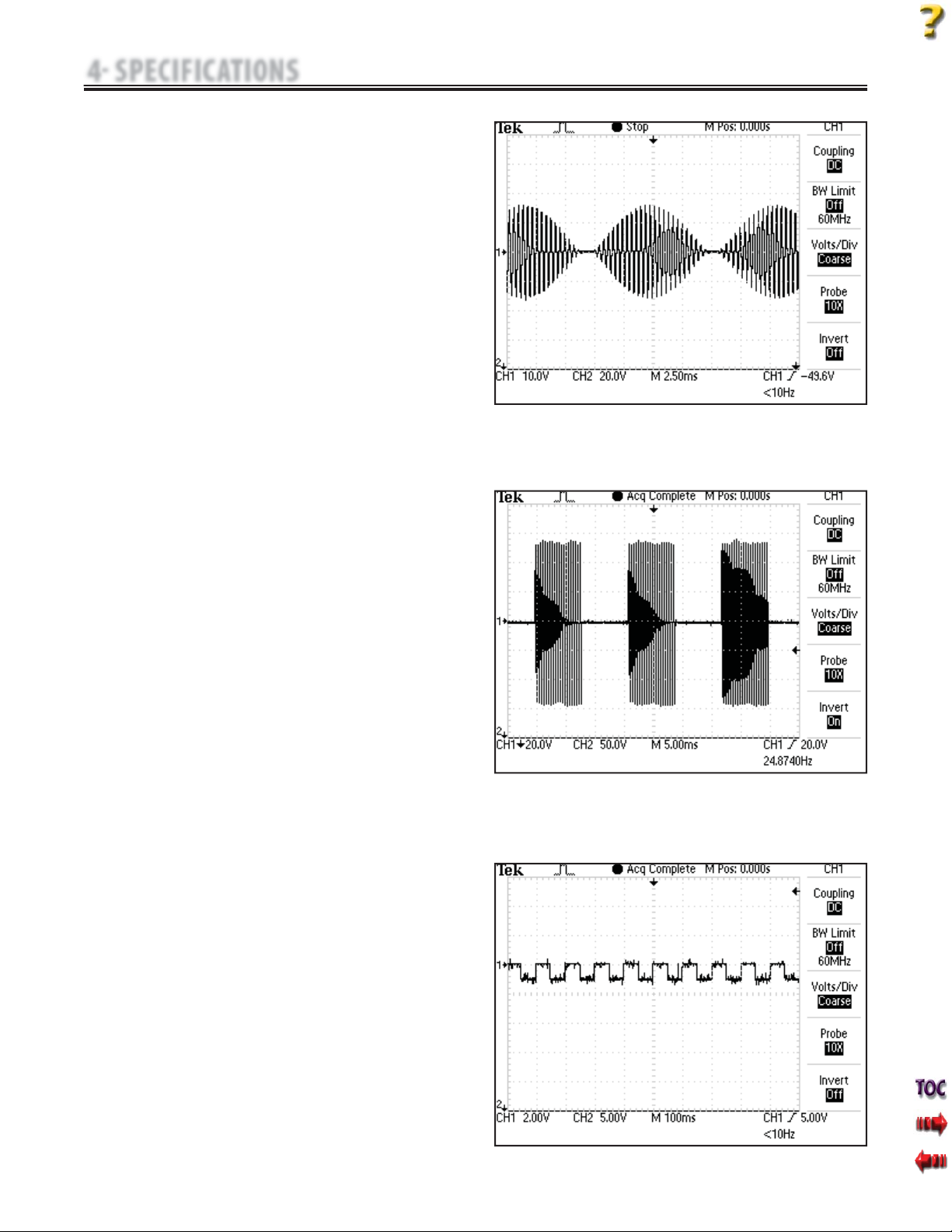
H. Russian- Figure 4.14
Russian Current is a sinusoidal waveform delivered in bursts or series
of pulses.This method was claimed by its author (Kots) to produce
maximal muscle strengthening effects without significant discomfort
to the patient.
Output Mode . . . . . . . . . . . . . . . . . . . . . . . . . . . . . . . . . . . . . . . Electrodes
Output Intensity. . . . . . . . . . . . . . . . . . . . . . . . . . . . . . . . . . . . . 0-100 mA
Channel Mode . . . . . . . . . . . . . . . . . . . . Single, Reciprocal, Co-Contract
Duty Cycle . . . . . . . . . . . . . . . . . . . . . .10%, 20%, 30%, 40%, and 50%
Mode Selection . . . . . . . . . . . . . . . . . . . . . . . . . . . . . . . . . . . . . CC or CV*
Anti-Fatigue . . . . . . . . . . . . . . . . . . . . . . . . . . . . . . . . . . . . . . . . . Off or On
Cycle Time . . . . . . . . . . . . . . . . . . . . . . . . . . . . . .5/5, 4/12, 10/10, 10/20,
10/30, 10/50, and Continuous
Burst Frequency (Anti-Fatigue Off). . . . . . . . . . . . . . . . . . . .20-100 pps
Ramp. . . . . . . . . . . . . . . .0.5 seconds, 1 seconds, 2 seconds, 5 seconds
Treatment Time. . . . . . . . . . . . . . . . . . . . . . . . . . . . . . . . . . . 1-60 Minutes
I. Microcurrent- Figure 4.15
Microcurrent is a monophasic waveform of very low intensity. The
literature reports beneficial effects of this waveform in the treatment
of wounds. The physiological working mechanism of this effect is as
yet not clearly understood. It is thought to promote tissue healing by
stimulating the "current of injury": a current which naturally occurs
in healing tissue.
Output Mode . . . . . . . . . . . . . . . . . . . . . . . . . . . . . . . Electrodes or Probe
Output Intensity. . . . . . . . . . . . . . . . . . . . . . . . . . . . . . . . . . 0-1,000.0 μA
Polarity . . . . . . . . . . . . . . . . . . . . . . . . .Positive, Negative, or Alternating
Treatment Time. . . . . . . . . . . . . . . . . . . . . . . . . . . . . . . . . . . 1-60 Minutes
*CC= Constant Current
CV= Constant Voltage
FIGURE 4.13
FIGURE 4.14
FIGURE 4.15
4 SPECIFICATIONS
4.3 INTELECT ELECTROTHERAPY WAVEFORM SPECIFICATIONS (continued)
15
Intelect® Mobile Stim and Combo Therapy Systems
*CC= Constant Current
CV= Constant Voltage
FIGURE 4.16
FIGURE 4.17
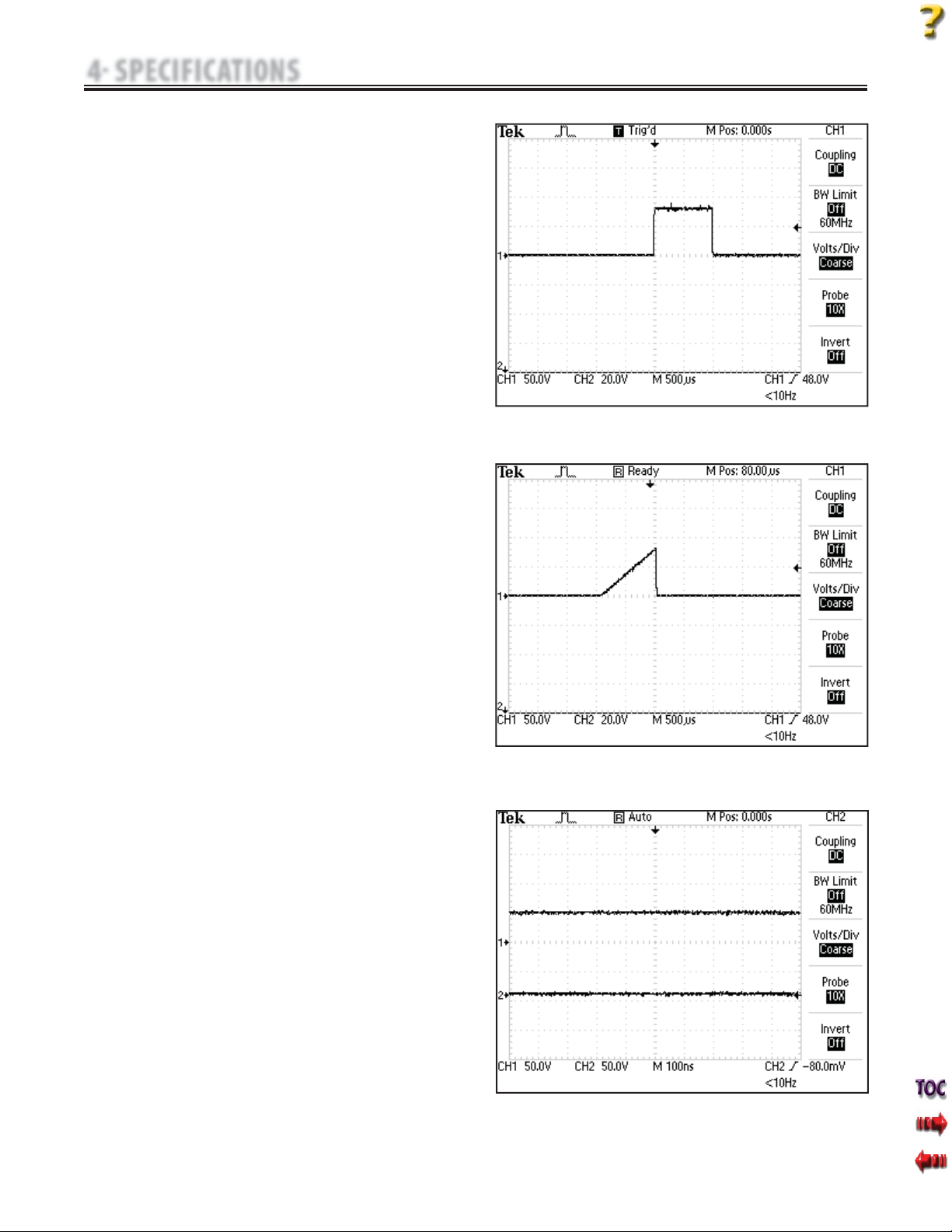
J. MONOPHASIC: Monophasic Rectangular Pulsed
Figure 4.16
The Monophasic Rectangular Pulsed waveform is an interrupted
unidirectional current with a rectangular pulse shape.
Output Mode. . . . . . . . . . . . . . . . . . . . . . . . . . . . . . . . . . . . . . . . Electrodes
Output Intensity . . . . . . . . . . . . . . . . . . . . . . . . . . . . . . . . . . . . . . 0-80 mA
Phase Duration . . . . . . . . . . . . . . . . . . . . . . . . . . . . . . . . . . . 0.1-500.0 ms
Phase Interval . . . . . . . . . . . . . . . . . . . . . . . . . . . . . . . . . . . . . .5-5,000 ms
Treatment Time . . . . . . . . . . . . . . . . . . . . . . . . . . . . . . . . . . . 1-60 Minutes
K. MONOPHASIC: Monophasic Triangular Pulsed
Figure 4.17
The MonophasicTriangular Pulsed waveform is an interrupted
unidirectional current with a triangular pulse shape.
Output Mode . . . . . . . . . . . . . . . . . . . . . . . . . . . . . . . . . . . . . . . Electrodes
Output Intensity. . . . . . . . . . . . . . . . . . . . . . . . . . . . . . . . . . . . . . 0-80 mA
Phase Duration . . . . . . . . . . . . . . . . . . . . . . . . . . . . . . . . . . 0.1-500.0 ms
Phase Interval . . . . . . . . . . . . . . . . . . . . . . . . . . . . . . . . . . . . .5-5,000 ms
Treatment Time . . . . . . . . . . . . . . . . . . . . . . . . . . . . . . . . . . 1-60 Minutes
L. GALVANIC: Continuous- Figure 4.18
Continuous Galvanic Current is a direct current flowing in one
direction only.
Output Mode. . . . . . . . . . . . . . . . . . . . . . . . . . . . . . . . . . . . . . . .Electrodes
Output Intensity . . . . . . . . . . . . . . . . . . . . . . . . . . . . . . . . . . . . . .0-80 mA
Polarity Reversal . . . . . . . . . . . . . . . . . . . . . . . . . . . . . . . . . . . . . .On or Off
With Polarity Reversal On, Polarity will change after
50% of treatment time.
Cycle Time . . . . . . . . . . . . . . . . . . . . . . . . . Continuous, 5/60, and 10/60
Treatment Time. . . . . . . . . . . . . . . . . . . . . . . . . . . . . . . . . . .1-60 Minutes
4 SPECIFICATIONS
FIGURE 4.18
4.3 INTELECT ELECTROTHERAPY WAVEFORM SPECIFICATIONS (continued)
16
Intelect® Mobile Stim and Combo Therapy Systems
FIGURE 4.19
FIGURE 4.20
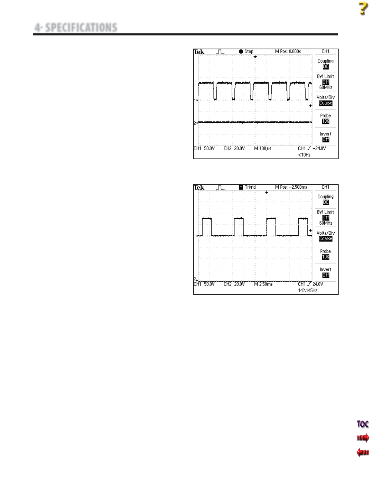
M. GALVANIC: Interrupted- Figure 4.19
Interrupted Galvanic Current is a direct current flowing in one
direction only. The current is delivered in pulses.
Output Mode. . . . . . . . . . . . . . . . . . . . . . . . . . . . . . . . . . . . . . .Electrodes
Output Intensity . . . . . . . . . . . . . . . . . . . . . . . . . . . . . . . . . . . . .0-80 mA
Polarity Reversal . . . . . . . . . . . . . . . . . . . . . . . . . . . . . . . . . . . . .On or Off
With Polarity Reversal On, Polarity will change after
50% of treatment time
Cycle Time. . . . . . . . . . . . . . . . . . . . . . . . . Continuous, 5/60, and 10/60
Frequency. . . . . . . . . . . . . . . . . . . . . . . . . . . . . . . . . . . . . . . . . . .8,000 Hz
Duty Cycle . . . . . . . . . . . . . . . . . . . . . . . . . . . . . . . . . . . . . . . . . . . . . 95%
Treatment Time . . . . . . . . . . . . . . . . . . . . . . . . . . . . . . . . . .1-60 Minutes
N. Träbert (Ultrareiz)- Figure 4.20
Träbert is a monophasic waveform with a phase duration of 2 ms
and a pause of 5 ms resulting in a frequency of approximately 143
Hz.
Output Mode. . . . . . . . . . . . . . . . . . . . . . . . . . . . . . . . . . . . . . .Electrodes
Output Intensity . . . . . . . . . . . . . . . . . . . . . . . . . . . . . . . . . . . . .0-80 mA
Polarity Reversal . . . . . . . . . . . . . . . . . . . . . . . . . . . . . . . . . . . . .On or Off
With Polarity Reversal On, Polarity will change after
50% of treatment time.
Treatment Time . . . . . . . . . . . . . . . . . . . . . . . . . . . . . . . . . .1-60 Minutes
4 SPECIFICATIONS
4.3 INTELECT ELECTROTHERAPY WAVEFORM SPECIFICATIONS (continued)
17
Intelect® Mobile Stim and Combo Therapy Systems
A. Ultrasound
Frequency. . . . . . . . . . . . . . . . . . . . . . . . 1 MHz, ± 5%; 3.3 MHz, ±5%
Duty Cycles. . . . . . . . . . . . . . . . . . . . 10%, 20%, 50%, and Continuous
Pulse Frequency . . . . . . . . . . . . . . . . . . . . . . . . . . .16 Hz, 48 Hz, 100 Hz
Pulse Duration. . . . . . . . . . . . . . . . . . . 1 mSec, ±20%; 2 mSec, ±20%
5 mSec, ±20%
Output Power
10 cm2Crystal. . . . . . . . . . . . . . . . . . . . . . . . . . . . .0-20Watts at 1 MHz,
0-10 Watts at 3.3 MHz
5 cm2Crystal. . . . . . . . . . . . . . . . . . . . . . . . 0-10 Watts, 1 and 3.3 MHz
2 cm2Crystal. . . . . . . . . . . . . . . . . . . . . . . . . .0-4 Watts, 1 and 3.3 MHz
1 cm2Crystal. . . . . . . . . . . . . . . . . . . . . . . . . . . 0-2 Watts 3.3 MHz Only
Amplitude . . . . . . . . . . . . . . . . . . . 0 - 2.5 w/cm2in Continuous mode,
0-3 w/cm2in Pulsed modes
Output accuracy . . . . . . . . . . . . . . . . ± 20% above 10% of maximum
Temporal Peak to Average Ratios:
2:1, ± 20%, at 50% Duty Cycle
5:1, ± 20%, at 20% Duty Cycle
9:1, ± 20%, at 10% Duty Cycle
Beam Nonuniformity Ratio. . . . . . . . . . 5.0 : 1 maximum
Beam Type . . . . . . . . . . . . . . . . . . . . . . . . . . . . . . . . . . . . . . . . Collimating
Effective Radiating Areas . . . . . . . . . . .10 cm2Crystal - 8.5 cm2, ±1.5
5 cm2Crystal - 4.0 cm2, ±1.0
2 cm2Crystal - 1.8 cm2, +0.2/-0.4
1 cm2Crystal - 0.8 cm2, +0.2/-0.4
Treatment Time . . . . . . . . . . . . . . . . . . . . . . . . . . . . . . . . . . 1-30 Minutes
B. Head Warming Feature Specifications
The HeadWarming feature of an Intelect Combination Therapy
System utilizes Ultrasound output resulting in warming of the Sound
Head to increase patient comfort.
With Head Warming enabled, ultrasound is emitted without pressing
the START button.The Applicator LED will not illuminate during the
Head Warming period. US Channel will indicate "Warming".
Output .. .. .. .. .. .. .. .. .. .. .. .. .. ..0 - 50% Cycling of maximum power
Frequency. . . . . . . . . . . . . . . . . . . . . . . . . . . . . . . . . . . . . . . . . . . . 3.3 Mhz
This section provides the necessary Ultrasound
Specifications to aid in troubleshooting.
Refer to these specifications as necessary when
troubleshooting the Ultrasound PC Board and Applicators.
Do not apply the Ultrasound Applicator to the patient during the Head
Warming period. Applicator must remain in Applicator Hook during the
Head Warming period.
4.4 INTELECT MOBILE COMBO ULTRASOUND SPECIFICATIONS
4 SPECIFICATIONS
18
Intelect® Mobile Stim and Combo Therapy Systems
A. The following information is provided as an aid in defining the
Software Error Messages of the Intelect MobileTherapy System. Once
a particular Error Message is defined, the information will also list
probable causes and possible remedies. Once the problem area is
determined, subsequent tests for verification will be necessary to
determine a“Bad Board”.
All Troubleshooting and tests will be to validate a“Bad Board”
only. No component level troubleshooting information is or will be
provided by Chattanooga Group for field troubleshooting of board
components.
B. Once a particular PC Board has been determined as bad, refer to the
appropriate Removal and Replacement Section for the board affected
and follow the instructions for replacement of the board.
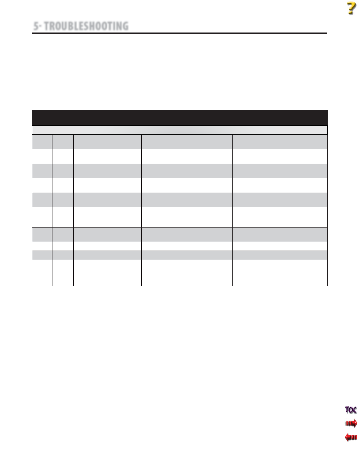
5.1 INTELECT MOBILE STIM AND COMBO ERROR MESSAGES
5 TROUBLESHOOTING
ERROR
CODE
ERROR
TYPE
DEFINITION PROBABLE CAUSES POSSIBLE REMEDY
USER CORRECTABLE WARNING MESSAGES
100 WARNING Ultrasound Applicator became unplugged. Ultrasound Applicator was unplugged while an Ultrasound
treatment was running.
Plug Ultrasound Applicator into proper receptacle on unit
making certain it is completely seated.
101 WARNING Ultrasound Applicator unplugged. User attempted to start an Ultrasound treatment, but no
Ultrasound Applicator was plugged into unit.
Plug Ultrasound Applicator into proper receptacle on unit
making certain it is completely seated.
102 WARNING Ultrasound Applicator not calibrated. The Ultrasound Applicator plugged into the unit needs to
be calibrated.
Contact dealer or Chattanooga Group for service.
103 WARNING Ultrasound Channel not available. User attempted to select Combo treatment, but the
Ultrasound Channel was already in use.
Wait until Ultrasound treatment is completed or stop
Ultrasound treatment and try again.
104 WARNING Stim Channel not available. User attempted to select an Electrotherapy or Combo
treatment, but all Stim Channels are in use.
Wait until Electrotherapy treatment is completed or stop
Electrotherapy treatment and try again.
105 WARNING Stim Channels not available. User attempted to select a two channel Electrotherapy
treatment, but at least one of the two stim channels were
already in use.
Wait until Electrotherapy treatment is completed or stop
Electrotherapy treatment and try again.
106 WARNING Overcurrent Stim channel has exceeded allowed current level and the
treatment has been stopped.
Reset treatement parameters and attempt session again.
107 WARNING Bad Contact Quality. Electrode contact is poor. Apply new electrodes to the treatment area.
108 WARNING Shorted LeadWires LeadWires are bad. Replace with new lead wires.
109 WARNING Power Supply current limit. User attempted to start two channels of Electrotherapy
while running an Ultrasound treatment with a 10 cm2
Ultrasound Applicator and Ultrasound Output is currently
set to greater than 15Watts..
Wait until Ultrasound treatment is completed or stop
Ultrasound treatment and try again or decrease ultrasound
output to less than 15Watts.
This manual suits for next models
1
Table of contents
Other Intelect Medical Equipment manuals


Popular Medical Equipment manuals by other brands


Getinge
Getinge Arjohuntleigh Nimbus 3 Professional Instructions for use

Mettler Electronics
Mettler Electronics Sonicator 730 Maintenance manual

Pressalit Care
Pressalit Care R1100 Mounting instruction

Denas MS
Denas MS DENAS-T operating manual

bort medical
bort medical ActiveColor quick guide

AccuVein
AccuVein AV400 user manual


