Intelight KASJOPEJA LED User manual
4 KTM 97133 - Instruction KASJOPEJA, EN, ver.20221123 1
FAULTY OPERATION AND ITS POSSIBLE DIAGNOSIS
Green LED (POWER) indicator does not li ht up
AC power failure.
Yellow LED (CHARGE) li hts up
Battery during charging process. LED will go off after the battery is full.
Red LED (FAULT) indicator li hts up
Battery not connected or damaged.
The luminaire does not operate in emer ency mode the required time for a selected model
It is possible that the battery re uires a full charge cycle (24h). If after 24 hours of charging the luminaire still does not keep a
predefined autonomy, it is possible that the battery is run-down or damaged due to possible incorrect formatting and needs to be
replaced.
RECOMMENDED PERIODICAL MAINTENANCE
The luminaire should be tested on regular basis in accordance with valid laws and regulations. The results of the tests should be
recorded and stored for the use of a fire safety inspector.
One time daily
It is suggested to check visually if the LED (POWER) indicator in the luminaire lights up in green.
One time each month
It is necessary to perform a function test by disconnecting the AC power supply and checking whether the luminaire is operating in
emergency mode - the green LED indicator should turn off, and LEDs light up.
One time each year
In order to make an autonomy test, disconnect the AC power supply and test if the luminaire operates in emergency mode for a
specified time. If the autonomy time of emergency operation is not sufficient, the battery needs to be fully recharged and the test
is to be carried out again. If the result of the test continues to be negative, the battery needs to be replaced.
CAUTION!
All damage that might occur as a result of the device being used not in accordance to this instruction will result in loss of guarantee.
Used or damaged lamps including batteries, are subject to be recycled. They should be delivered to the point of collection of
electrical and battery waste or to the manufacturer.
The light source contained in this
luminaire shall only be replaced by the
manufacturer or his service agent or a
similar ualified person.
Handlin of obsolete equipment
Pursuant to the Act of 29 July 2005 on waste
electrical and electronic e uipment and the Act
of 24 April 2009 on batteries and accumulators,
the presented device, after use, due to
hazardous substances contained in it, is subject
to collection of waste electrical and electronic
e uipment. Detailed information on WEEE
collection can be obtained from municipal
authorities.
Inteli ht Sp. z o.o.
19, Gwiaździsta str.
01-651 Warsaw, Poland
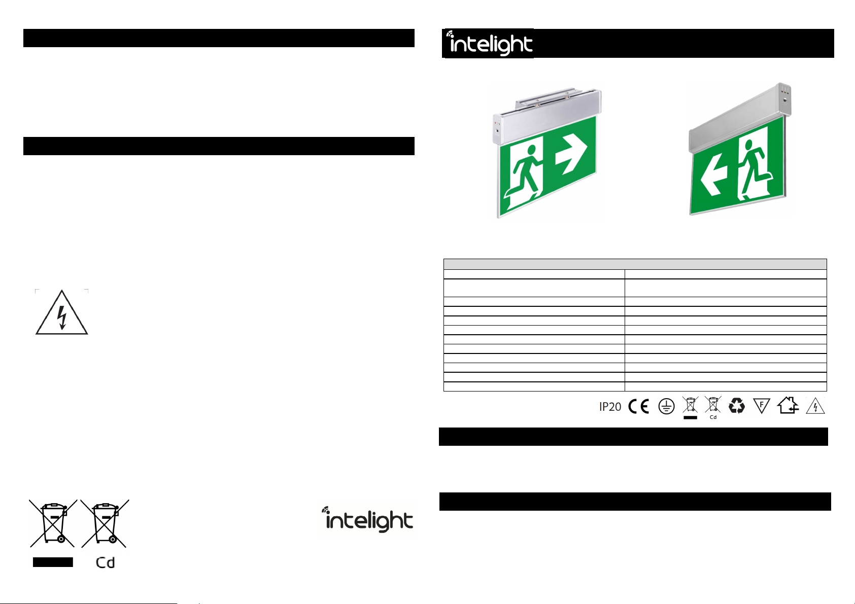
KASJOPEJA LED EMERGENCY LUMINAIRE
Inst ll tion nd m inten nce instructions
KASJOPEJA LED
OV
TECHNICAL SPECIFICATIONS:
Light source (user non-replaceable): White LED
Operating modes *: SA (M) - mains and emergency operation or
A (NM) - emergency operation
Test versions: MT – manual test
Emergency autonomy *: 1h, 2h or 3h
Battery (user non-replaceable) *: NiCd or NiMH 3.6V 400mAh ÷ 800 mAh
Battery charging duration max.: 24h
Power supply *: 220-240V AC 50Hz (for MT) or 230V AC / 220V DC (for CB)
Max. power: 2W
Module: Kasjopeja LED
Visibility: 30 metres
Enclosure IP rating: IP20
Ambient temperature: 10°C ÷ 40°C
*- depending on model
INTRODUCTION
1. The lamp should be installed when power supply is off. Safety rules, construction and electrical installation standards should
be followed all the time.
2. The luminaire should not be powered with circuits connected to inductive power-receiving devices at the same time. This type
of solution may cause damage to the electronic module of the luminaire.
3. The luminaire should be used indoors.
INSTALLATION
1. Before installation one has to make sure that the luminaire will be connected to 220-240VAC power supply by the use of a
minimum 1,5mm2 wire.
2. Connecting the battery:
- the battery should be already connected;
- if it is not connected, one need to remove housing’s plastic end cap from the signal panel’s side, then slide off housing’s
aluminium cover and insert white battery plug into its socket; after connection one need to slide the housing’s cover and the
cap back into their positions.

2 3
3. Using a supplied mounting bracket the luminaire can be mounted either on ceiling or on wall.
4. In order to fix the installation bracket, one need to use screws (max. Ø6 for a ceiling installation or max. Ø5 for a wall
installation), according to the below drawings.
5. Before installing the luminaire’s housing one need to stick desired pictograms on to a diffuser plate.
6. Then, one need to insert installation bracket’s spring grips, one after another, into the housing’s profile, by means of
dedicated round hole in its upper part, according to the below drawings (a – inserting first grip, b – sliding the luminaire, c –
inserting second grip, d – positioning the luminaire).
Important – one need to install the luminaire in a way that makes the information label visible for people who will carry out
testing in future.
7. Prepare power cable and connect all the wires to the appropriate terminal block entries.
8. The description of luminaire’s wires:
L - phase wire - brown or black insulation colour; power source for Maintained operation and battery charging; presence
signaled by the green LED
N - neutral wire - blue insulation colour
PE - earth wire - yellow and green insulation colour
Important – one need always to remember about connecting the protection earth wire (PE)
9. EMERGENCY OPERATION. If a luminaire is made as Non-Maintained version (A/NM), after proper wiring (connecting L, N and
PE wires, NM jumper removed) it should be constantly supplied by power - voltage drop will result in emergency mode
activation, the luminaire will light up.
10. MAINS AND EMERGENCY OPERATION. If a luminaire is made as Maintained version (SA/M), after proper wiring (connecting L,
N and PE wires) it should be constantly supplied by power - voltage drop will result in emergency mode activation, the
luminaire will switch from mains to battery supply, being still lit up.
11. It is suggested to indicate the date of installation on the label attached to the battery pack or in another place visible for
maintenance staff.
12. For uick operation testing – switch on the AC power supply. The green LED indicator should light up, signaling proper work
and battery charging.
13. First-time charge of the luminaire battery pack should be carried out continuously for 48 hours. This will allow appropriate
formatting of the battery pack. During the first-time charge, no testing should be carried out and power supply should not be
disconnected for any other purpose. Power supply should be disconnected after 48 hours for the first time. The luminaire
should complete a full emergency operation cycle, after which it should be connected to power supply for another 36 hours.
This se uence shall complete the formatting cycle.
OPERATION
Emer ency operation mode
In this mode (A / NM) the luminaire does not light when powered by AC supply voltage. Correct operation of the device is
confirmed by LED (POWER) indicator lighting up in green. The battery is being continuously trickle charged for the purpose of a
possible emergency operation, what is signalled by LED (CHARGE) indicator lighting up in yellow. When AC power supply is off, the
luminaire automatically starts operating in emergency mode and the source of light is activated for the period specific for a
particular model.
Mains and emer ency operation mode
In this mode (SA / M) the luminaire lights up when powered by AC supply voltage. Correct operation of the
device is also confirmed by LED (POWER) indicator lighting up in green. The battery is being continuously trickle charged for the
purpose of possible emergency operation, what is signalled by LED (CHARGE) indicator lighting up in yellow. When AC power supply
is off, the luminaire automatically starts operating in emergency mode and the source of light is switched from mains to battery
supply, for a period specific for a particular model.
Information on lamp operation
The luminaire operates correctly and charging circuit works if the LED (POWER) indicator lights up in green. During basic charging
cycle, additionally LED (CHARGE) indicator lights up in yellow, it goes off after a battery is fully charged. If green LED (POWER) is off,
it means that the luminaire is not operating with AC supply on. If LED (FAULT) indicator becomes red, it means that the luminaire is
not working correctly, e.g. the battery is not connected, damaged or worn.
Battery pack
The luminaire is e uipped with a rechargeable Ni-Cd or Ni-MH battery pack. Please remember to carry out the correct first-time
charge cycle. After such a formatting cycle it achieves its capacity and is prepared to perform a possible full time emergency
operation. It is recommended to replace the battery once every four years of operation or in a case of poor test results. Obsolete
batteries, similarly to packaging, fluorescent lamps or electronics, are recyclable products that should be disposed to a recyclable
waste collection point.
TESTING
KASJOPEJA LED luminaire is e uipped with a TEST button, which enables to test emergency operation of the luminaire.
MT manual test function
When the emergency luminaire is connected to mains and there is no voltage drop, pressing and holding TEST button will result in
activation of the “voltage drop” mode, the green LED (POWER) will go off and the luminaire should light up. When the button is
released - the luminaire will switch back into its standard operation mode.
The above action means that in a case of emergency mode version the luminaire will go from unlit to illuminated. In a case of mains
and emergency mode the luminaire will change a power source, from mains to a battery supply, the switch-over moment should be
visible as a uick blink – during a very short while the light source will be off.
CB central battery version
Note – CB version can be e uipped in a test button, however it is in this case inactive. The button pressing will not cause any
luminaire’s reaction.
CB version is being monitored directly by a central battery system controller, in a way depending on such system’s possibilities and
settings.
WALL INSTALLATI
ON
CEILING INSTALLATION
a
a
b
c
c
d
Other Intelight Lantern manuals

Popular Lantern manuals by other brands


eLEDing
eLEDing EE818plus user manual

Elgo
Elgo LINESMART OLN 402 Installation and operating instruction

Patriot Lighting
Patriot Lighting DJ9014BK installation instructions

Eterna
Eterna HL60B installation instructions

Smartwares
Smartwares GWS-001-DS instructions

McLED
McLED Orbis ML-611.318.17.0 installation manual

Deluce Lighting
Deluce Lighting LED RGB IP65 Strip Kit Fitting instructions

IKEA
IKEA SOLVINDEN J2007 quick start guide

LUG
LUG CRUISER 2 LB LED DALI Installation instruction

Selux
Selux Connect M60 LED SX 116 Mounting instructions

Lenmar
Lenmar SOLV17 owner's manual

Heitronic
Heitronic Frankfurt 501312 Installation and operating instructions