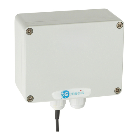
IntellyGreenPV ZR-REP-E230M Installation guide

Specifications of the device
Size: 90 mm x 100 mm x 36 mm
Weight: 130 g
Power supply: 230 Vac (±10%); 20mA; 50/60Hz
Operating Range: -10°C ÷ +60°C; <80%
Protection Degree: IP 55
Radio: Transmission Power 10 mW (10 dBm)
2405 -2480 MHz frequency
Sensitivity -97 dBm
External antenna with a gain of 5.5 dBm
DSSS Modulation
Ember Chip EM250,
Stack Zigbee PRO Ember
Range: 50m (indoor) / 200m (outdoor)
The Repeater ZR-REP-E230M serves to extend the radio range of a
network of devices of the IntellyGreenPV family.
Its use is necessary when the presence of obstacles or excessive
distance disturb the communication between the sensors (Radio
Transmitter and SIS sensor) and the data concentrator (In-house
Display).
The presence of one or more repeaters also allows greater network
redundancy, making it more reliable.
The device must be continuously powered by 230V.
The device consists of:
(1) no. 1 repeater ZR-REP-E230M including
(2) no. 1 2-pin European plug (CEE 7/16), wired with a 2m cable
(3) no. 1 Antenna.
Overview of the device ZR-REP-E230M
The repeater consists of three parts:
A) Cover
B) Box with built-in electronics
C) Antenna
1. Turn the cover (A) counter clockwise to open the device
2. Secure the box (B) to the wall
3. Screw in the antenna (C) vertical to the floor
4. When the assembling is completed close the cover (A) by
turning it clockwise.
Caution! The box (B) contains electronic components.
Do not knock the components. Handle with care.
Assembling the device
Caution! Connect the device to a line adequately protected
against short circuits and overloads exceeding the maximum
power handling.
Caution! Connect the equipment as established by national law.
Installation Notes
The radio range of the repeater reaches two hundred meters outdoor,
i.e. in absence of obstacles.
Indoor environments, the range is severely limited and highly variable
depending on the case.
Thick walls or reinforced slabs can be a hard obstacle to overcome.
The best position of the Repeater is hard to define, in some cases it
must be found by trial and error.
Basic rules of installation:
Install the repeater in an intermediate position between the
In-house Display and the sensor (SIS sensor or other
sensors).
Install the repeater in an elevated position above the floor.
Install the Repeater away from metallic objects, especially
if large.
Install the repeater, if possible, so that the devices are in
sight.
Verify the installation:
After the installation and association, turn on the repeater and after
one minute of operation check if the flashing of the LEDs means the
actual connection to the In-house Display (see "light signals").
Finally, verify on the In-house Display that the data from the most
remote of the sensors (for example, the sensor SIS) is present and
has a good signal.
Powering the device
(3)
(1)
(2)
IntellyGreenPV
Assembling Instructions
4-noks s.r.l. –Francenigo di Gaiarine (TV) - Italy
(A) (B) (C)

Operating controls specifications
Button
If pressed for longer than 10 seconds the repeater is reset to the original
state (disconnected device).
This action causes the loss of data relating to the network radio
communication and the loss of connection with the Remote Display and
all devices connected to it.
Light signals
Led
State
Description
LD1
LD2
LD3
Solid light of all the
LEDs with a brief
flash every 20
seconds.
Indicates that the transmitter is
not connected to any radio
network.
LD1
Flashing light.
Slow flashing indicates that the
transmitter is operating normally.
Quick flashing indicates that the
network is open and therefore
allows the association of new
devices.
LD2
Flashing light.
The flashing indicates the device
is connected via radio to the
Remote Display
The number of flashes indicates
the number of connected devices
with strong radio signal.
Install the device in proper position and turn it on.
When you first switch on the device, verify that it is not attached to any
radio network (the LEDs are all switched on and perform a quick flash for
two seconds every 20 seconds), otherwise disconnect the device by
pressing the button for more than 10 seconds.
Acting on the Remote Display, open the radio network (menu/Radio
Management/ Open Radio Network) following these steps:
A few seconds after opening the network, the repeater should connect to
the radio network of the remote display. The operation's success is
evidenced by the flashing of led LD1 of the device.
If the Repeater is still disconnected after 30 seconds of the network
opening, probably the location chosen for the device is not suitable; in that
case bring the repeater closer to the remote display or to another repeater.
When finished, close the radio network by In-house Display.
Association to the In-house Display (network Joining)
Standards
Regulations: 2006/95/CE, 89/336/CE, 99/5/CE
Standards: EN 300 328, EN 301 489,
EN 61000-6-2, EN 6100-6-3,EN 60950-1
In case of disposal, the products must be disposed of separately in
accordance with applicable local laws.
Disposal
Warranty Conditions
The warranty period is 2 years from the date of installation or 30 months
from the date of manufacture.
The warranty applies only in UK.
The manufacturer agrees to replace or repair the components that are
found defective.
Damage caused by improper installation, by a power supply not
compliant with the CEI EN 50160 standard, by the incorrect use or
failure to comply with the instructions contained in the Assembling
Installation is not covered by the warranty.
Note:
INSTRUCTIONS
INPV
SERIES
001
VERSION
1.3
Date
03/2011
Confirm this request to open
the In-house Display radio
network.
At the end of the
association, confirm this
request to close the In-
house Display's radio
network.
Press the button under
"Menu".
Select the "Radio
Management" menu
Select "Open Radio
Network"
4-noks s.r.l. –Francenigo di Gaiarine (TV) - Italy
LD1
LD2
LD3
