9
a
d
e
bc
C
F
F
D
E
A
B
Service - maintenance
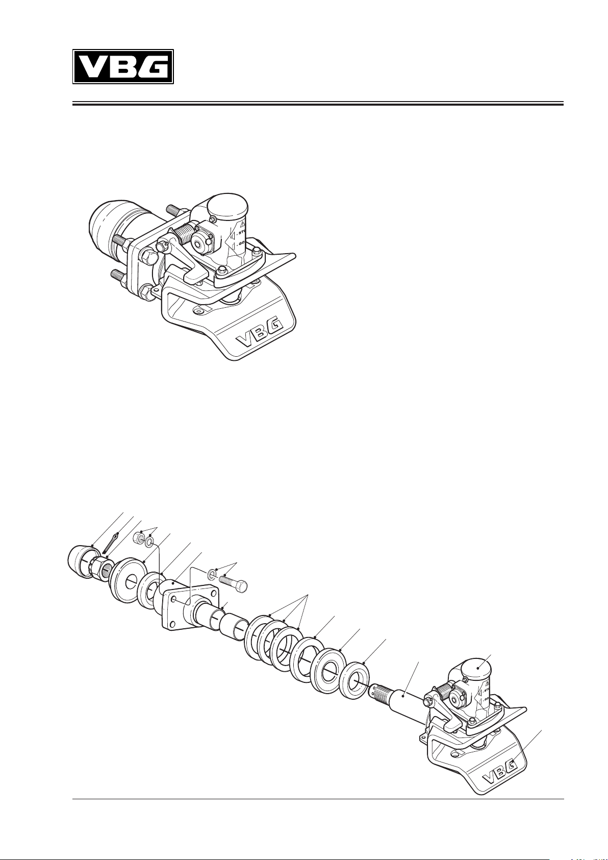
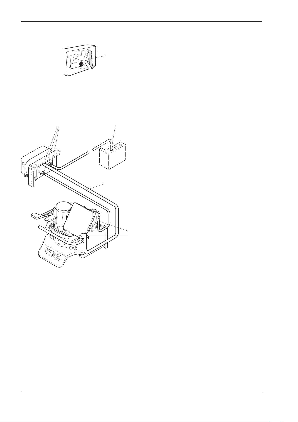
Change of mechanism and bushings
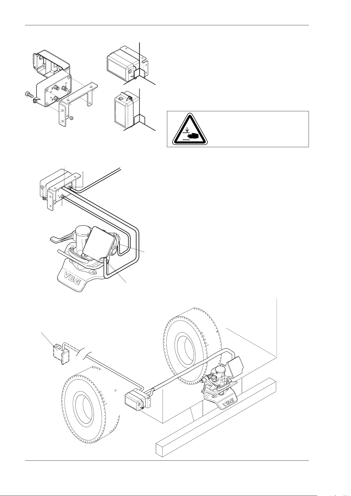
If the coupling is equipped with a power actuator, the air
supply to the control box must be cut off before work
with the coupling is started.
• Remove the mechanism by loosening the four screws
and lift the mechanism from the coupling jaw.
• Remove the wear plate.
Wear parts
(a) Mechanism
(b) Upper and lower jaw bushings
(c) Drawbar eye wear ring
(d) Rubber bearings and drawbeam sleeve bushings
(e) Wear plate
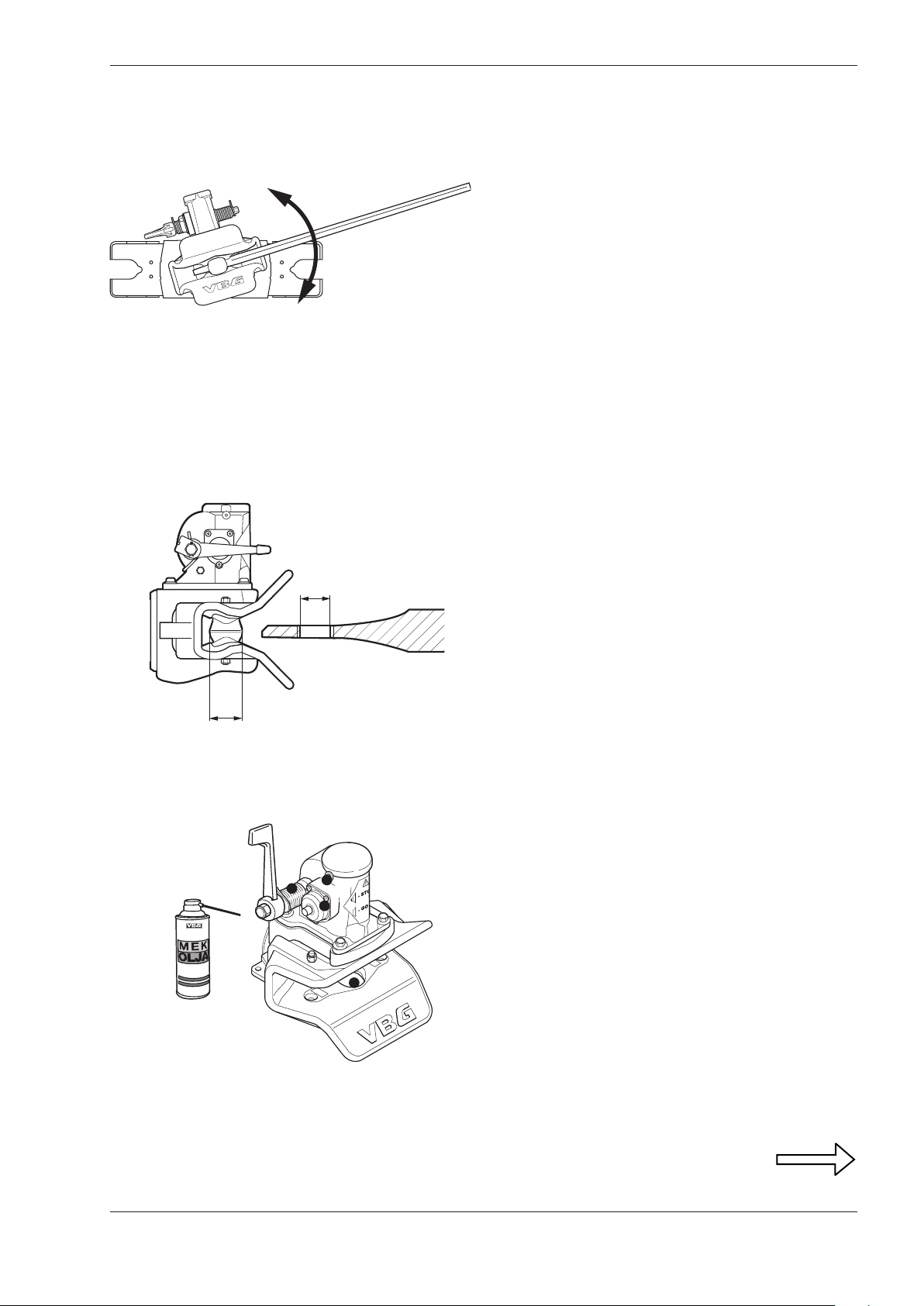
Wear limits
A inner diameter max 59.5 mm
B outer diameter min 57.0 mm
C inner diameter max 45.7 mm
D outer diameter min 42.5 mm
E outer diameter min 55.0 mm
F Wear plate mark on wear plate
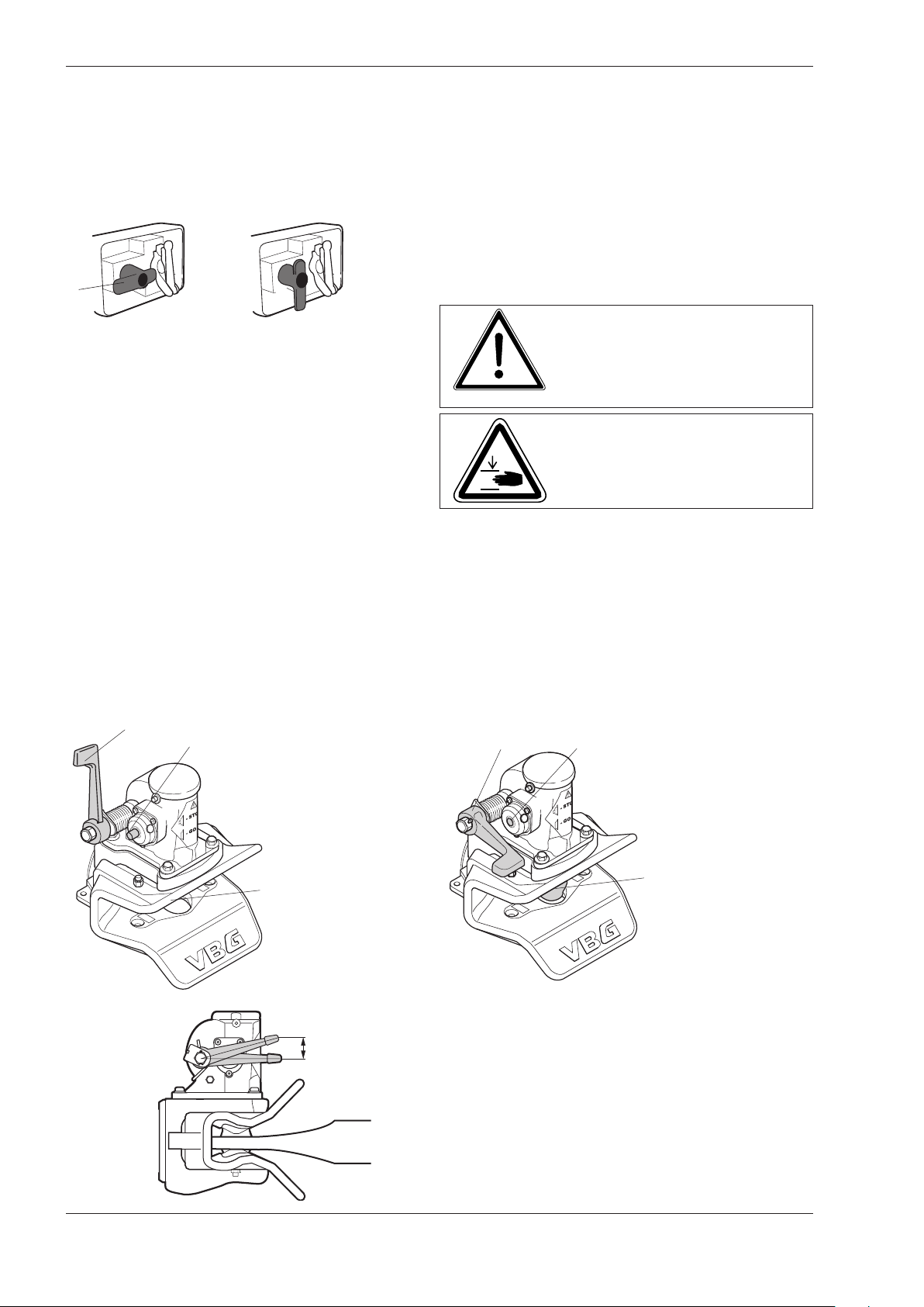
Vertical play
in the coupling bolt max 5.0 mm
• It is important to remember that a coupling is a safety
critical item and should be treated as such. Proper
preventive maintenance, inspection and lubrication are
essential for a long, safe and trouble-free service life.
• The length of service intervals depends on the type of
trailer, load, road- and weather conditions etc. Servicing
can best be carried out when other work or inspection
of the vehicle is done, for example every 60 000 or 90
000 km.
• At least once a year the coupling must be dismounted
and inspected for wear, corrosion, cracks or de-forma-
tion. Worn out or damaged parts must be replaced.
• If the daily overhaul or safety check shows that any
of the wear limits have been exceeded or that the
coupling´s function is reduced, repairs must be carried
out immediately.
• The fact that one of the coupling´s wear limits have
been exceeded indicates that other parts need service
as well. Therefore, always remove the coupling from the
drawbeam when changing the mechanism and bush-
ings. Check the mounting parts and the drawbeam and
replace worn out rubber bearings and bushings.