International Electronics 212iL User manual

6060720 Rev. 1.1
1
212iL
6060720 Rev. 1.1
2
212iL (illuminated Luxury) Keypad
Single Unit Keypad- Control Installation Manual
Features:
v120 User Capability
vIlluminated Backlit Hardened Keys
vProgrammable 00-99 Second Relay Activation Time
vRemote Trigger Input (REX)
vHeavy Traffic Application
vFlush Mount
vIndoor Applications
Installation:
qSection 1: Unpacking and checking the packing list
qSection 2: Mounting the 212iL
qSection 3: Wiring the 212iL
qSection 4: Power Up
qSection 5: Programming the 212iL
qSection 6: Troubleshooting
qSection 1: Unpacking and checking the packing list
Open the box, and inside you will find:
1212iL keypad
16 Wire conductor harness
21 1/4" black, socket cap flat head machine screws
21 1/4" black, Phillips flat head sheet metal screws
111/64" Allen wrench
1Installation Manual for 212iL
Please check the contents of this package and verify all components in the packing list are present.
Taking this inventory will familiarize you with the components as well as ensure that you have a
complete parts list.
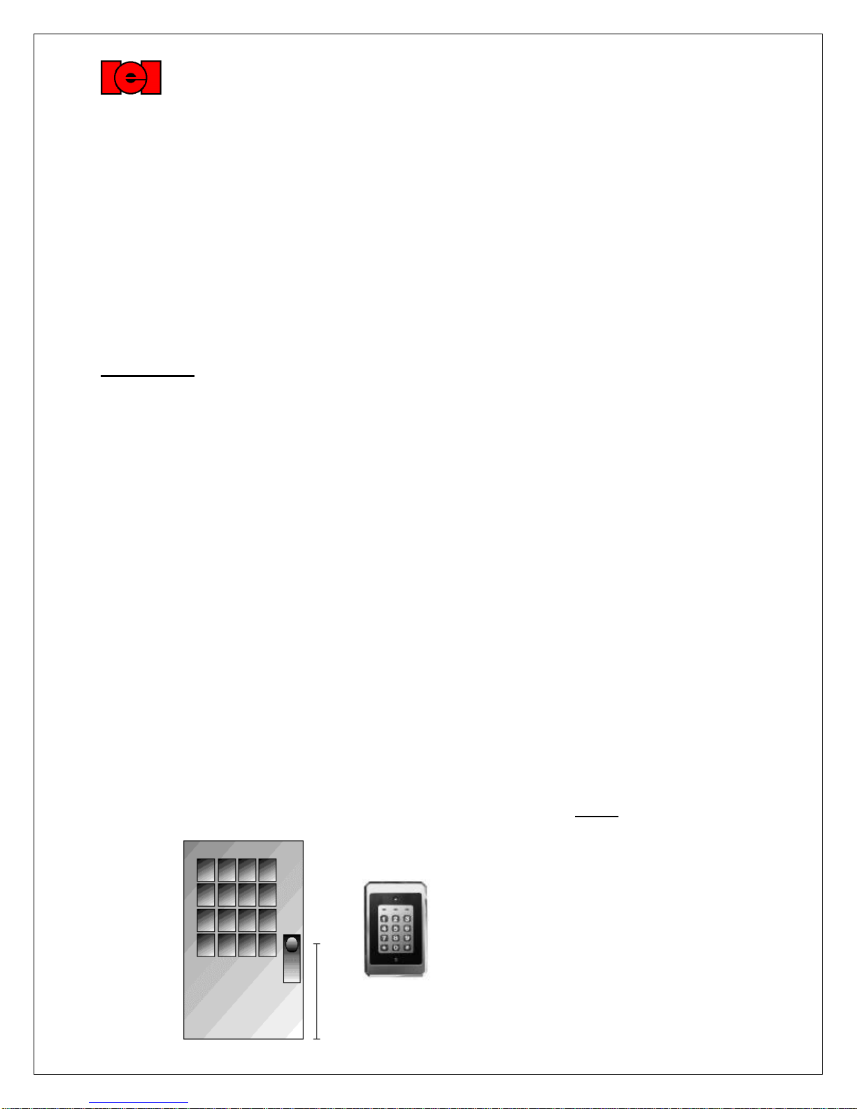
qSection 2: Mounting the 212iL (212iL Dimensions: 3 3/8" x 5 1/8" x 5/8")
1. Select the appropriate location for the 212iL. Mounting height is the same for an electrical
switch, 48" on center. Be sure that the 212iL is mounted indoors ONLY!
International Electronics, Inc.
427 Turnpike Street
Canton, Massachusetts 02021
48"
6060720 Rev. 1.1
3
The 212iL should be mounted to a standard single gang electrical box (with the small slot in the
trim ring facing down), but it also is able to mount directly to a flat indoor surface with the provided
mounting screws.
qSection 3: Wiring
Electrical Specifications:
Operating Voltages: 12-24 VDC only on input voltage.
Maximum Current Draw @ allowed voltages: 140mA.
Temperature Tolerance: Standard, -20° to 130°F.
1. Attach the 6-conductor wire harness to the plug in connector on the back of the 212iL.
2. Next you will need to attach the relay wires (white/yellow, blue, and brown) to the wire run that is
connected to the locking device.
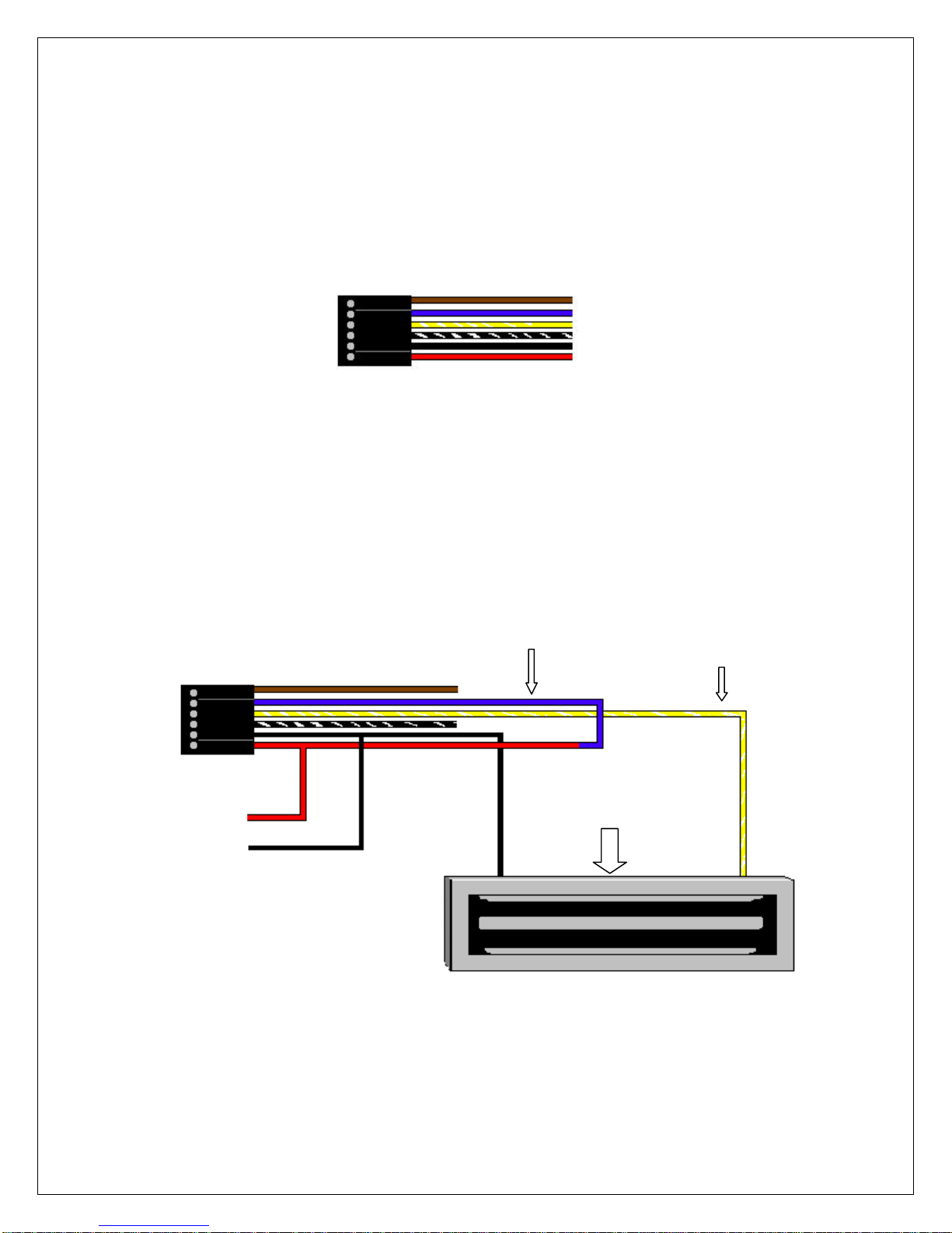
Wiring to a Magnetic Lock: (see below)
If you are sharing the same DC voltage power supply with the 212iL and the magnetic lock, (that is to
say if you have only one power supply for both the 212iL and the lock device), you need to run voltage
through the common (Blue) wire on the 6 conductor wire harness of the 212iL. The reason is that the
212iL is equipped with a Form C, Dry contact relay on board. This means that there is no voltage running
through the relay. (Until you supply the common leg of the relay with voltage).
Step 1: Splice together the Blue Relay Common wire from the 212iL harness to the Red wire on
the 212iL harness. (Positive voltage coming from the power supply.)
Step 2: Connect the White /Yellow wire (Normally Closed) from the 212iL harness to the Positive
connection on the Magnetic lock.
Step 3: Splice together the Black Negative voltage wire on the 212iL harness (negative voltage
coming from the power supply) to the Negative connection on the Magnetic lock.
Wiring to an Electric Strike: (see below)
If you are sharing the same DC voltage power supply with the 212iL and the Electric Strike, (that
is to say if you have only one power supply for both the 212iL and the lock device), you need to run
voltage through the common (Blue) wire on the 6 conductor wire harness of the 212iL. The reason is that
Magnetic Lock
(Fail Safe)
Blue (C) Wire
White/Yellow (N/C) Wire
V+
V
-
V
-
V+
Brown (N/O) Wire
Blue (Common) Wire
White/Yellow (N/C) Wire
White/Black (REX) Wire
Black (Negative) Wire Input
Red (Positive) Wire Input

6060720 Rev. 1.1
4
the 212iL is equipped with a Form C, Dry contact relay on board. This means that there is no voltage
running through the relay. (Until you supply the common leg of the relay with voltage).
Step 1: Splice together the Blue Relay Common wire from the 212iL harness to the Red wire on
the 212iL harness. (Positive voltage coming from the power supply.)
Step 2: Connect the Brown (Normally Open) wire from the 212iL harness to the Positive voltage
connection on the Electric door strike.
Step 3: Splice together the Black Negative voltage wire on the 212iL harness (negative voltage
coming from the power supply) to the Negative connection on the Electric door strike.
Shunting a Normally Closed Zone: (see below)
Step 1: Connect the Blue (Common) Relay wire from the 212iL harness to the Common
connection on the door position switch.
Step 2: Connect the Brown (Normally Open) Relay wire from the 212iL harness to the Normally
closed connection on the Door position switch.
Electric Strike
(Fail Secure)
Brown (N/O)
Wire
V+
V
-
Blue (C) Wire
V+
V
-
Brown (N/O)
Wire
Blue (Common) Wire
Normally
Closed
Door
Position
Contacts
V+
V
-
To Alarm Panel
To Alarm Panel
6060720 Rev. 1.1
5
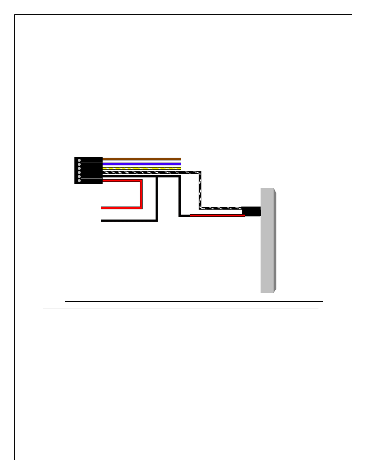
Wiring to a Request to Exit (Push to release):
The 212iL keypad may be wired to monitor a remote-switching device, and is meant to be
installed on the secured side of the door. This is a momentary input that will engage the main relay for
the same amount of time that the master code is programmed with. This input requires a momentary
closure between the White with a Black trace wire and the Black wire. The only time the REX won't follow
the main relay time is if the Master code has been programmed to latch the main relay. In this case, the
REX will operate with the default time of 5 seconds. You may wire in several devices parallel to release
the door from different locations. There is no programming required for this option.
Step 1: Connect the White with Black trace wire on the 212iL harness to the common connection
on the REX device.
Step 2: Splice a wire to the Black (negative) wire on the 212iL harness and connect to the
Normally Open connection on the REX device.
Example wiring to an IEI request to exit device (part # EZ-REX):
If your REX device sends voltage when it is pressed, you must connect an external relay to
the wires coming from the REX, then connect the 212iL REX connections to the common and the
normally open connections on the external relay.
qSection 4: Power Up
Making the Power Connections: (The 212iL is powered with 12-24 VDC ONLY)
Step 1: Connect the Red (Positive voltage input) wire from the 212iL harness to the
positive voltage output connection on the power supply.
Step 2: Connect the Black (Negative voltage input) wire from the 212iL harness to the
negative voltage output connection on the power supply.
Upon power up, the 212iL will cycle through the LED's from left to right twice to indicate proper keypad
operation. (If the LED's continue to flash, refer to the trouble shooting section of this manual). The
Backlighting will now be on and will dim 15 seconds after the last keypress or 5 seconds after the
programming mode has been exited. Perform the Self-Test by pressing 7890#123456*. The LED’s will
cycle from Green to Yellow to Red and then the sounder will beep three times.
White/Black Wire
Black (Negative) Wire
V
-
V+

6060720 Rev. 1.1
6
qSection 5: Programming the 212iL
The 212iL supports 120 user codes that will operate the keypad and energize the main relay. A user
code is stored in the memory of the 212iL with an individual user location, and may be 1 to 6 digits in
length. Each user code has an associated user location. To help with the understanding of user
locations, think of them like shelves. The 212iL has 120 shelves (user locations) in it, and each user
code gets put into its own shelf (user location). For example: the Master code, factory defaulted to
1234, is always stored with user location 1. Every time a new user code is added, the user location
must be advanced by one digit. To do any programming the 212iL must be put into the Programming
Mode.
Step 1: Entering the Programming Mode.
Programming is accessed by entering the command that tells the 212iL that programming is the
desired function. The command is always as follows:
99 followed by the # key.
Next the current Master Code has to be entered.
Then finish the command by pressing the * key.
Example: 99 # 1234 *
If the programming command was done successfully, the 212iL will start flashing the yellow LED
slowly, indicating that it is now in the programming mode. If the yellow does not come on
flashing, that is an indication that the incorrect Master code was entered. (Validate the Master
code).
Step 2: Changing the Master Code.
The 212iL comes with the factory programmed Master code of 1234. This may be changed to
any code that has 1 to 6 digits in length. The 212iL also comes set from the factory with a 5
second relay activation time that may be changed to any time from 01 to 99 seconds.
The 212iL has to be in programming mode before you can change the Master code.
To Change the Master code:
Enter Programming Mode: 99# (Master code) * (Yellow LED flashing slowly).
Next enter user location "1" which is always the Master code’s user number.
Next enter in the new Master code followed by the * key (Yellow LED flashes rapidly).
Repeat the new Master code followed by the * key. (Yellow LED will flash slowly).
If the change was successful, the yellow LED will still be flashing.
Example: 1 # 4321 * 4321 *
To Change the Main Relay Activation Time:
Enter Programming Mode: 99# (Master code) * (Yellow LED flashing slowly).
Next enter the relay activation time in a two digit format "08" for 8 seconds.
Next enter user location "1" which is always the Master code’s user number.
Next enter in the Master code followed by the * key (Yellow LED flashes rapidly).
Repeat the Master code followed by the * key. (Yellow LED will flash slowly).
If the change was successful, the yellow LED will still be flashing.
Example: 08 # 1 # 4321 * 4321 *
To exit the programming mode press the * key. Or continue for more programming.

6060720 Rev. 1.1
7
Step 3: Adding or Changing User Codes.
User codes may be 1 to 6 digits in length.
The 212iL has to be in programming mode to add or change users
To program:
Enter Programming Mode: 99# (Master code) *
Next enter the user location. (2, 3, 4, …)
Now enter the new code followed by the * key (Yellow LED flashes rapidly).
Repeat the new code followed by the * key (Yellow LED will flash slowly).
If the change was successful, the yellow LED will still be flashing slowly. Codes entered in this
fashion will hold the relay time programmed with the master code.
Example: 2 # 6789 * 6789 *
3 # 5378 * 5378 *
4 # 23966 * 23966 *
To exit the programming mode press the * key. Or continue for more programming.
Step 4: Creating a User Code to Latch the Main Relay.
A latching user code is used when the need to have the device that is being controlled by the
212iL activate or deactivate for an indefinite amount of time. This operates much like a light
switch. When you enter a latching user code, the Main relay will activate and stay activated until
the same code or a like latching user code is entered to deactivate the relay.
To program:
Enter Programming Mode: 99# (Master code) *
Next enter the relay time of "00"
Next enter the user location. (2, 3, 4, …)
Now enter the new code followed by the * key (Yellow LED flashes rapidly).
Repeat the new code followed by the * key (Yellow LED will flash slowly).
If the change was successful, the yellow LED will still be flashing slowly.
Example: 00 # 12 # 7788 * 7788 *
00 # 55 # 6632 * 6632 *
00 # 93 # 78651 * 78651 *
To exit the programming mode press the * key. Or continue for more programming
Step 5: Changing the 212iL Feedback Options.
The 212iL has two key-press feed back options that you may choose from. One is an audio feed
back. This will activate the on board sounder every time that a key is pressed. The other is a
visual feed back. This will flash the yellow LED on the front of the keypad every time that a key is
pressed. These two options are used to verify that a key has been successfully pressed. Both of
these options may be used together.
Audio Option:
To program:
Enter Programming Mode: 99# (Master code) *
Next press Command number 30 followed by the # key.
Next press "0" for the audio feed back option followed by the # key.
Next press "0" to Disable or "1" to Enable the audio option followed by the # key.
Next press the * key (Yellow LED flashes rapidly).
Next press the * key (Yellow LED will flash slowly).
Example: 30 # 0 # 0 # * * (This will disable the sounder from activating every time a key is pressed).

6060720 Rev. 1.1
8
Visual Option:
To program:
Enter Programming Mode: 99# (Master code) *
Next press Command number 30 followed by the # key.
Next press "1" for the visual feed back option followed by the # key.
Next press "0" to Disable or "1" to Enable the visual option followed by the # key.
Next press the * key (Yellow LED flashes rapidly).
Next press the * key (Yellow LED will flash slowly).
If the change was successful, the yellow LED will still be flashing slowly.
Example: 30 # 1 # 0 # * * (This will disable the yellow led from activating every time a key is pressed).
Step 6: Auto-Entry.
Auto entry is used when the need for the code not to be followed by the * key is desired. The
user only needs to enter their code number and the relay will activate for the programmed relay
time. To use this feature, the user codes must be the same length as the Master code.
The 212iL has to be in programming mode to change any option.
To program:
Enter Programming Mode: 99# (Master code) *
Next press Command number 30 followed by the # key.
Next press "2" for the Auto-Entry option followed by the # key.
Next press "0" to Disable or "1" to Enable the Auto-Entry option followed by the # key.
Next press the * key (Yellow LED flashes rapidly).
Next press the * key (Yellow LED will flash slowly).
If the change was successful, the yellow LED will still be flashing slowly.
Example: 30 # 2 # 1 # * * (This will remove the * key from the code).
Step 7: Reset to Factory Default.
This command is used when the user numbers are not known which makes it possible to change
or delete the codes. When this command has been done successfully the 212iL will be reset to
the factory default settings of 1234 as the Master code and 05 seconds as the relay activation
time.
To program:
Enter Programming Mode: 99# (Master code) *
Next press Command number 46 followed by the # key.
Next press the "0" key five times followed by the # key.
Next press the "0" key five times followed by the # key.
Next press the * key (Yellow LED flashes rapidly).
Next press the * key (Yellow LED will flash slowly).
If the change was successful, the yellow LED will still be flashing slowly.
Example: 46 # 00000 # 00000 # * *
If the Master code is not working or has been forgotten, power down the 212iL and connect the
White with Black trace wire to the Red wire and power up the 212iL. This will put the 212iL into
program mode indicated by the flashing yellow LED. Next enter 46#00000#00000# * * to default
the keypad. Power down to remove the White/Black wire from the Red wire.

6060720 Rev. 1.1
9
Programming Options Chart
If the pre-programmed default values must be changed
Or additional functions are desired, the following options may be programmed.
1. Enter programming mode Press 99 # (master code) *
2. Changing the master code Press 1#(new code) *(repeat code) *
3. Change the main relay activation timeNOTE 1 Press (relay time) #1#(master code) *(repeat code) *
Example: Master code with a 8 second relay time Press (08) # 1 # 1234 *1234 *
4. Add or change user codesNOTE 2 Press (user location) #(new code) *(repeat Code) *
5. Add a user to latch the main relayNOTE 1 Press (00) #(user location) #(new code) *(repeat code) *
6. Turn audible keypress feedback ON Press 30 # 0# 1# * *
7. Turn audible keypress feedback OFF Press 30 # 0# 0# * *
8. Turn visual keypress feedback ON Press 30 # 1# 1# * *
9. Turn visual keypress feedback OFF Press 30 # 1# 0# * *
10. Turn Auto-Entry ON Press 30 # 2# 1# * *
11. Turn Auto-Entry OFF Press 30 # 2# 0# * *
12. Erase keypad memory and reset defaults Press 46 # 00000 # 00000 # * *
NOTES:
NOTE 1. Relay time must be represented in a two-digit format. For example 5 seconds is entered as 05.
Latching relay time is entered with a time of 00.
NOTE 2. Codes entered in this fashion will hold the relay time that the master code is programmed with.
For a detailed explanation of each option please refer to prior pages 5-7.

6060720 Rev. 1.1
10
qSection 6: Trouble Shooting.
Refer to this section if the 212iL is not responding correctly to the operation outlined in this instruction
manual. The 212iL has been designed to operate with 12-24 VDC only. Verify that the voltage
powering this keypad is within these parameters.
Situation 1: LED's are slowly cycling from right to left and the Backlighting is off.
Reason: The 212iL has been designed to monitor for low voltage. Once the low voltage
has been detected, the keypad shuts down some of its options like backlighting
to ensure operation of the keypad until the problem can be attended to.
Solution: Check the output voltage of the power supply with a meter to verify the output
voltage rating listed for that device. If it is below the voltage threshold of 9 VDC,
you must increase the voltage beyond the minimum rating of 9 VDC.
Situation 2: LED's are rapidly cycling from left to right and the keypad has lost all
operation.
Reason: The 212iL has been designed to monitor for over voltage. This is a very "severe"
condition and therefore significantly affects the keypad’s operation. Once the
over voltage has been detected, the keypad shuts down all operation and will not
operate until the voltage irregularity has been corrected.
Solution: Check the output voltage of the power supply with a meter to verify the output
voltage rating listed for that device. If it is over the voltage threshold of 30 VDC,
you must reduce the output below the threshold.
Situation 3: The Master code is not allowing access to the programming mode.
Reason: There are a few reasons that this situation could occur. The most common is
that the Master code was programmed incorrectly. That is to say that someone
used the incorrect user number to add a user code. The Master code is always
kept in memory with user number "1".
The other reason this could happen is that the code was simply forgotten.
Solution: Power down the keypad, connect the white/black wire to the Red wire on the
212iL wire harness and power back up. The yellow LED will be flashing
indicating that the keypad is now in programming mode. Change the Master
code by press 1 # (New Master Code) * (Repeat Master Code) * *. When
finished with programming, power down the unit, separate the white/black wire
from the Red wire on the 212iL harness and power back up. The keypad is now
ready to use.
Situation 4: No LED's are lit on the keypad
Reason: Power is not reaching the keypad.
Solution: With a meter check the voltage connection at the 212iL keypad on the Red &
Black wires. Confirm that there is actually voltage at the keypad. If there is no
voltage reading at the keypad, use the meter on the power supply to verify that
voltage is leaving the power supply. If there is no voltage coming out of the
power supply, call the manufacturer of that power supply. If there is voltage at
the power supply, but not at the keypad, use the meter to test each of the wires
for a break in the wire.

6060720 Rev. 1.1
11
International Electronics Incorporated (IEI) warrants its products to be free
from defects in material and workmanship, when they have been installed in
accordance with the manufacturer’s instructions, and have not been modified or
tampered with. IEI does not assume any responsibility for damage or injury to person or
property due to improper care, storage handling, abuse, misuse, normal wear and tear,
or an act of God.
IEI’s sole responsibility is limited to the repair (at IEI’s option) or the replacement of the
defective product or part when sent to IEI’s facility (freight and insurance charges
prepaid), after obtaining IEI’s Return Merchandise Authorization. IEI will not be liable to
the purchaser or any one else for incidental or consequential damages arising from any
defect in, or malfunction of, it’s products.
This warranty shall expire two years after shipping date for Door Gard Keypads. Except
as stated above, IEI makes no warranties, either expressed or implied, as to any matter
whatsoever, including, without limitation to, the condition of its products, their
merchantability, or fitness for any particular application.
INTERNATIONAL
ELECTRONICS, INC.
427 Turnpike Street
Canton, MA 02021 U.S.A.
Phone:(781) 821-5566
(800) 733-9502 Sales in MA
(800) 343-9502 Sales
FAX: (781) 821-4443
Visit our Web Site at www.ieib.com
Table of contents
Other International Electronics Keypad manuals


