manuals.online logo
Brands
  1. Home
  2. •
  3. Brands
  4. •
  5. GE
  6. •
  7. Keypad
  8. •
  9. GE Interlogix Aritech ATS1155 User manual

GE Interlogix Aritech ATS1155 User manual

Other GE Keypad manuals

GE NX-1300E User manual

GE

GE NX-1300E User manual

GE NX-148E - Security NetworX LCD Keypad User manual

GE

GE NX-148E - Security NetworX LCD Keypad User manual

GE KTD-404 Operating instructions

GE

GE KTD-404 Operating instructions

GE NX-148E-RF - Security NetworX NX-8E System User manual

GE

GE NX-148E-RF - Security NetworX NX-8E System User manual

GE 60-924-3-01 - ITI Simon 3 Wireless Touch Talk... Instruction sheet

GE

GE 60-924-3-01 - ITI Simon 3 Wireless Touch Talk... Instruction sheet

GE Interlogix Aritech ATS1155 User manual

GE

GE Interlogix Aritech ATS1155 User manual

GE NX-148E - Security NetworX LCD Keypad Manual

GE

GE NX-148E - Security NetworX LCD Keypad Manual

GE LCD Keypad User manual

GE

GE LCD Keypad User manual

GE NX-1448E - Security NetworX 48-Zone Fixed User manual

GE

GE NX-1448E - Security NetworX 48-Zone Fixed User manual

GE NetworX NX-1192E User manual

GE

GE NetworX NX-1192E User manual

GE AL-1111 User manual

GE

GE AL-1111 User manual

GE NetworX NX-1500E User manual

GE

GE NetworX NX-1500E User manual

GE KTD-405 User manual

GE

GE KTD-405 User manual

GE NetworX NX-1500E User manual

GE

GE NetworX NX-1500E User manual

GE NX-148E - Security NetworX LCD Keypad User manual

GE

GE NX-148E - Security NetworX LCD Keypad User manual

GE IC754VSI06SKD User manual

GE

GE IC754VSI06SKD User manual

GE NX-1348E-ICON User manual

GE

GE NX-1348E-ICON User manual

GE NetworX NX-1600E Series User manual

GE

GE NetworX NX-1600E Series User manual

GE Dialog QS1500 00 Touchtalk User manual

GE

GE Dialog QS1500 00 Touchtalk User manual

GE KTD-405 User manual

GE

GE KTD-405 User manual

GE AL-1103 User manual

GE

GE AL-1103 User manual

GE AL-1103 User manual

GE

GE AL-1103 User manual

GE NX-148E - Security NetworX LCD Keypad User manual

GE

GE NX-148E - Security NetworX LCD Keypad User manual

GE 45146- - Keypad Transmitter Remote User manual

GE

GE 45146- - Keypad Transmitter Remote User manual

Popular Keypad manuals by other brands

AAA 6150RFAAA Installation and setup guide

AAA

AAA 6150RFAAA Installation and setup guide

Fermax MDS Installation and programming manual

Fermax

Fermax MDS Installation and programming manual

ACT ACT PRO 1030 manual

ACT

ACT ACT PRO 1030 manual

Cardin SSB Series manual

Cardin

Cardin SSB Series manual

Harman Kardon KP 1 Specifications

Harman Kardon

Harman Kardon KP 1 Specifications

CYP CR-KP1 Operation manual

CYP

CYP CR-KP1 Operation manual

Aeware k-35 Series Quick reference card

Aeware

Aeware k-35 Series Quick reference card

Aritech CS-175 Series user guide

Aritech

Aritech CS-175 Series user guide

Lenze AC Tech MC SERIES installation instructions

Lenze AC Tech

Lenze AC Tech MC SERIES installation instructions

Burg Wächter secuENTRY 7711 operating instructions

Burg Wächter

Burg Wächter secuENTRY 7711 operating instructions

Aeware in.k450 Tech book

Aeware

Aeware in.k450 Tech book

Lenze EPM-H410 operating instructions

Lenze

Lenze EPM-H410 operating instructions

Toshiba RKP007Z user manual

Toshiba

Toshiba RKP007Z user manual

Elmes Electronic KB1 quick start guide

Elmes Electronic

Elmes Electronic KB1 quick start guide

Clare Controls ClareOne CLR-C1-PNC Installation sheet

Clare Controls

Clare Controls ClareOne CLR-C1-PNC Installation sheet

FM Electronics 4180 quick start guide

FM Electronics

FM Electronics 4180 quick start guide

AMX MIO-PRESTIGE-S Dimensional drawing

AMX

AMX MIO-PRESTIGE-S Dimensional drawing

why pro WHY-KP user manual

why pro

why pro WHY-KP user manual

manuals.online logo
manuals.online logoBrands
  • About & Mission
  • Contact us
  • Privacy Policy
  • Terms and Conditions

Copyright 2025 Manuals.Online. All Rights Reserved.

© 2003 GE Interlogix B.V. MAINST-ATS1155
All rights reserved 07/2003
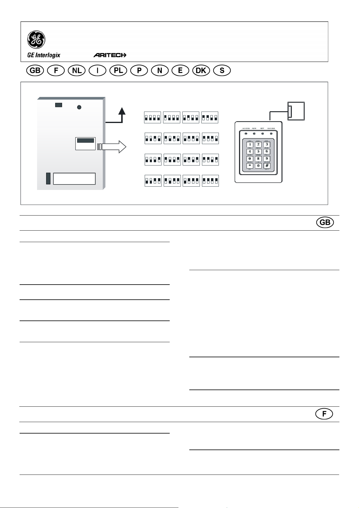
Dipswitches
1234
ON
RAS 1
1234
ON
RAS 2
1234
ON
RAS 3
1234
ON
RAS 4
1234
ON
RAS 5
1234
ON
RAS 6
1234
ON
RAS 7
1234
ON
RAS 8
1234
ON
RAS 9
1234
ON
RAS 10
1234
ON
RAS 11
1234
ON
RAS 12
1234
ON
RAS 13
1234
ON
RAS 14
1234
ON
RAS 15
1234
ON
RAS 16
J10
ATS4000


IN OUT D- D+ - +
1 2 3 4
{
|
}
~


Heavy Duty 4 LED RAS
MOUNTING THE UNIT
The unit is supplied as a kit consisting of a keypad and separate
electronics. It can be mounted on the surface, or if required, installed
in a custom enclosure.
Note: Mount the unit at an acceptable height so that it is easy
to operate without needing to reach up, and the LED’s
can be easily seen.
CONNECTING CONTROL PANEL TO KEYPAD (FIGURE )
Refer to the ATS control panel installation guide for instructions.
RAS DIP SWITCH SETTINGS (FIGURE )
{SW1 "ADDRESS" dip switches 1 to 4 are used to identify this RAS
number.
LED’S (FIGURE )
TX LED flashes to indicate the arming station (RAS) is replying
to polling from the ATS control panel.
LED INDICATIONS ON KEYPAD (FIGURE )
ACCESS (Disarmed) Illuminates when at least one of the areas
assigned to the arming station is disarmed, and when a
PIN is used to open a door, the LED flashes for the unlock
time.
ALM (Alarm) Illuminates when an alarm has occurred in one of
the areas assigned to the arming station.
RDY •When connected to the control panel, it illuminates when
the area is ready to be armed (system clear). ie. all inputs
normal, or
•When connected to an 4-door/4-lift DGP, it illuminates
when ready to accept a PIN code.
SECURE Illuminates when the area is armed.
When All LED’s are flashing, the arming station is not being polled.
CONNECTIONS J2 TERMINALS (FIGURE )
Power supply. If the distance between the arming station
and the control panel does not exceed 100m, then the
arming station can be powered using the Comms + and –
from the control panel. Otherwise use AUX PWR from
DGP’s or an auxiliary power supply.
D+ Data positive and data negative connection of the databus.
D - Remote units can be up to 1.5 km from the ATS control
panel.
IN A request to exit button (normally open, momentary push-
button switch) can be connected across “IN” and “-“. When
pressed, this button controls the request to exit function.
OUT Open collector output, 50 mA maximum. It is the first
output of the output control group that is assigned to this
arming station.
LINKS (FIGURE )
~GND Must remain fitted.
TERM Fitted if this device is the last device on the system
databus. For more details see the ATS control panel
installation guide.
CONNECTION FROM ELECTRONICS TO KEYPAD |(FIGURE )
Via a standard cable supplied with this product.
RAS renforcée à 4 voyants
MONTAGE DE L’UNITE
L’unité est fournie sous forme de kit, comprenant un clavier et une
électronique séparée. Elle peut être montée en saillie ou, si besoin
est, installée dans un coffret personnalisé.
Remarque :Installez l’unité à une hauteur appropriée afin qu’elle soit
bien à votre portée pour que vous puissiez la faire
fonctionner et voir sans problème les voyants lumineux.
RACCORDEMENT DE LA CENTRALE AU CLAVIER (FIGURE )
Reportez-vous au guide d’installation de la centrale ATS pour obtenir
des instructions à ce sujet.
+
-
ATS1155
Heavy Duty 4 LED RAS
Technical Data Specifications
techniques
Technische specificaties Specifiche Tecniche
Power supply Alimentation Voedingsspanning Tensione di alimentazione 10,5 - 13,8 V.
Current consumption Consommation électrique Stroomverbruik Assorbimento 70 mA max.
Dimensions (H x W) Dimensions (H x L) Afmetingen (H x B) Dimensioni (l x h x p) 118 mm x 75 mm.
Operating temperature: Température de
fonctionnement
Bedrijfstemperatuur: Temperatura di esercizio 0°C to + 50°C.
Humidity: Non condensing. Humidité sans
condensation
Vochtigheidsgraad:
condensvrij
Umidità senza condensa 95%
Dane Techniczne Dados técnicos Tekniske spesifikasjoner Especificaciones
técnicas
Napięcie zasilania Tensão de alimentação Forsyningsspenning Tensión de alimentación 10,5 - 13,8 V.
Pobór prądu Consumo de corrente Strømforbruk Consumo de corriente 70 mA max.
Wymiary (W x S) Dimensões (A x L) Størrelse (B x H Dimensiones (alto x ancho) 118 mm x 75 mm.
Temperatura pracy: Temperatura de operação Driftstemperatur Temperatura de
funcionamiento:
0°C to + 50°C.
Wilgotność: bez
kondensacji
Humidade: Sem
condensação.
Kondensfri fuktighetsgrad Humedad: sin
condensación.
95%
Tekniske Data Teknisk specifikation
Strømforsyning Spänningsmatning
10,5 - 13,8 V.
Strømforbrug Strömförbrukning 70 mA max.
Mål (H x B) Mått (H x B) 118 mm x 75 mm.
Driftstemperatur: Drifttemperatur 0°C to + 50°C.
Fugtighed: Ingen
kondensdannelse
Luftfuktighet: Ej
kondenserande
95%