Essex Electronics K1 Series Service manual

Essex Electronics, Inc. | 805.684.7601 | 800.KEY-LESS | fax 805.684.0232 | keyless.com
INSTALLATION & INSTRUCTION MANUAL
K1 Series
All-In-One 12-Pad

Essex Electronics, Inc. | 805.684.7601 | 800.KEY-LESS | fax 805.684.0232 | keyless.com
i
All rights reserved. No part of this documentation may be reproduced in any
form, without prior written consent of Essex Electronics, Inc. Essex Elec-
tronics shall not be liable for errors contained in this manual. The informa-
tion in this document is subject to change without notice. Essex Electronics,
Inc. reserves the right to modify this documentation and to make improve-
ments or changes to the product(s) contained in this documentation at any
time.
Document Information
IOMK1 Installation/Operations Manual for the K1 Series All-In-One 12-Pad
3x4 and 2x6 - July 2016. This documentation is also applicable to prior revi-
sions except where noted.
Product Information
This device complies with Part 15 of the FCC rules. Operation is subject to
the following two conditions: (1) This device may not cause harmful interfer-
ence, and (2) this device must accept any interference including interfer-
ence that may cause undesired operation.
Trademarks
Keyless Entry® is a registered trademark of Essex Electronics, Inc.
Contact Information
Essex Electronics, Incorporated
1130 Mark Avenue, Carpinteria, CA 93013
(805) 684-7601 or (800) 539-5377 (KEY-LESS)
FAX (805) 684-0232
Website: keyless.com
Copyright© 2005 Essex Electronics, Inc. All rights reserved.
K1 Series All-In-One 12-Pad
Multi-Format Keypad Reader

Essex Electronics, Inc. | 805.684.7601 | 800.KEY-LESS | fax 805.684.0232 | keyless.com
ii
Introduction....................................................................................1
Overview - The K1 Series................................................................1
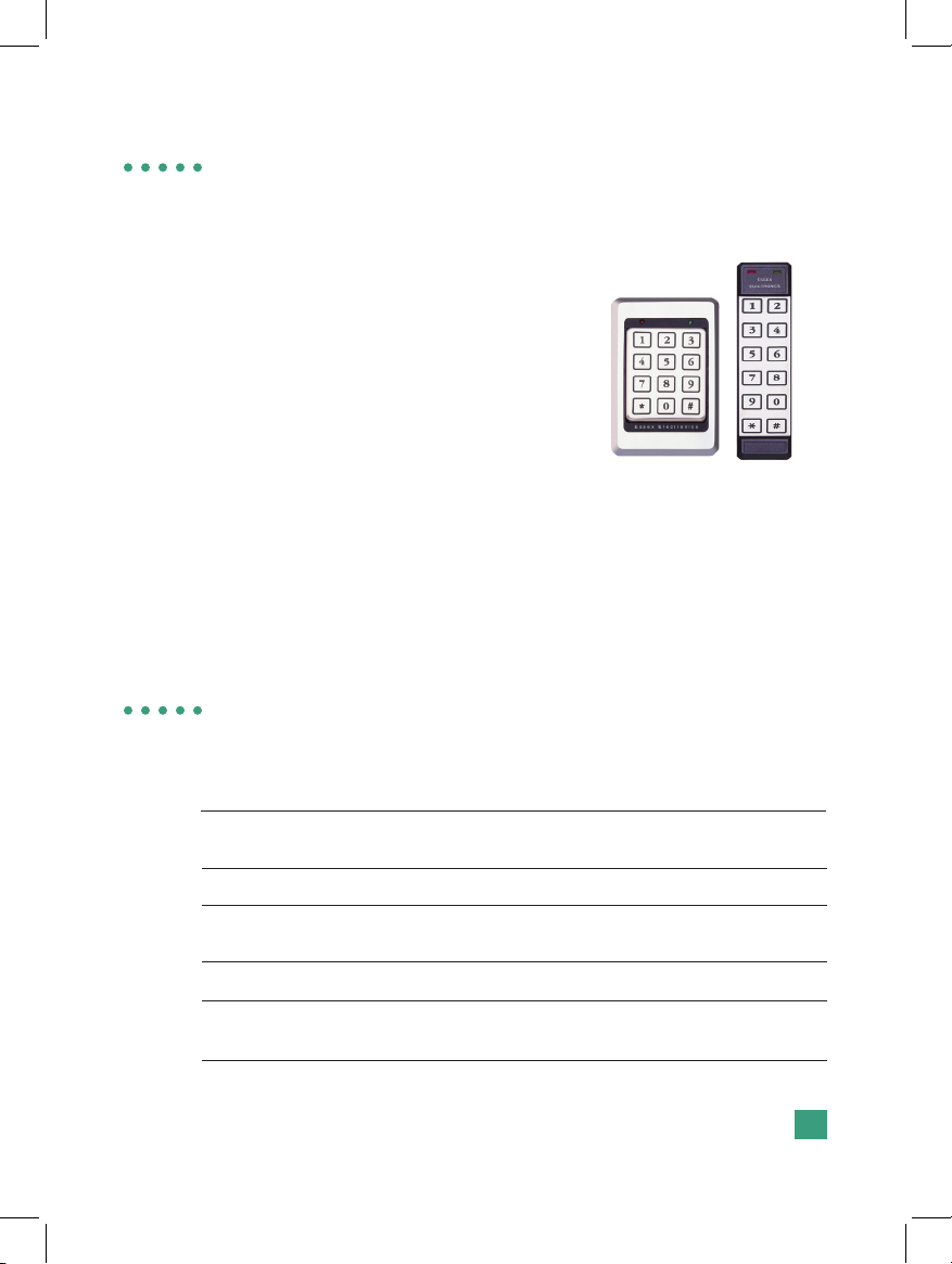
Keypad ............................................................................................1
Keypad Specications .....................................................................1
Keypad Part Numbers .....................................................................2
Keypad Conguration......................................................................3
26 Bit Wiegand Keypad Reader....................................................7
26 Bit Wiegand Specications.........................................................7
26 Bit Wiegand Connector Wiring ................................................... 9
8 Bit Word Keypad Reader ......................................................... 11
8 Bit Word Specications............................................................... 11
8 Bit Word Connector Wiring.........................................................12
BCD Keypad Reader....................................................................14
BCD Specications........................................................................14
BCD Connector Wiring ..................................................................15
Serial ASCII Keypad Reader .......................................................16
Serial ASCII Specications ............................................................ 16
Serial ASCII Connector Wiring ......................................................19
ABA Track II Clock & Data Reader .............................................20
ABA Track II Specications............................................................ 20
ABA Track II Connector Wiring......................................................21
4 Bit Word Keypad Reader ....................................................22
4 Bit Word Specications..........................................................22
4 Bit Word Connector Wiring....................................................23
Warranty & Repairs .....................................................................28
Table of Contents

Essex Electronics, Inc. | 805.684.7601 | 800.KEY-LESS | fax 805.684.0232 | keyless.com
iii

1
Essex Electronics, Inc. | 805.684.7601 | 800.KEY-LESS | fax 805.684.0232 | keyless.com
Introduction
Overview – The K1 Series
3x4 Keypad (left) and 2x6
Keypad (right)
The Essex K1 Series All-In-One 12-Pad
Multi-Format is an extremely versatile
Keypad that can be congured in the eld
as any one of the following:
26 Bit Wiegand Keypad Reader
8 Bit Word Keypad Reader
BCD Keypad Reader
Serial ASCII Keypad Reader
ABA Track II Clock & Data Reader
4 Bit Word Keypad Reader
500 user-code, stand-alone Keyless Entry® System (See
the “K1 Series All-In-One 12-Pad Self-contained Keyless
Entry® System” manual)
Input Voltage: 5VDC or 12 to 24VDC (Jumper
Selectable)
Standby Current Draw: 25mA
Outputs: 4 Open Collector, 1/4 A Max to
Ground
Keypad Switch Life: >1 Billion Cycles
Keypad Operating Environment: -40°C to +70°C (-40°F to +160°F),
100% Relative Humidity
Keypad
Keypad Specications

Essex Electronics, Inc. | 805.684.7601 | 800.KEY-LESS | fax 805.684.0232 | keyless.com
2
Keypad
Keypad Specications, cont’d.
3x4 Keypad Dimensions: 5-1/8”H x 3-3/8”W x 7/16”D
(13 x 8.6 x 1.1 cm)
2x6 Keypad Dimensions: 7-1/8”H x 1-3/4”W x 3/4”D
(13 x 8.6 x 1.1 cm)
3x4 Keypad Weight: 16 oz (454 gm)
2x6 Keypad Weight: 4.4 oz (125 gm)
LED’s: 1 Red, 1 Green
Keypad Part Numbers
3x4 Keypad
K1-34S Stainless Steel Bezel
K1-34K Black Bezel
K1-34X No Bezel
2x6 Keypad
K1-26I Illuminated
K1-26S Stainless Steel Overlay

3
Essex Electronics, Inc. | 805.684.7601 | 800.KEY-LESS | fax 805.684.0232 | keyless.com
Keypad Conguration
Voltage Selection
The factory default setting for the Keypad voltage is 12-24VDC.
Verify that the jumper is removed or placed over only one pin. For
5VDC, the jumper should be placed across both pins. If changing
the voltage is necessary, make sure the power is removed rst.
Keypad Output Selection
Once the voltage jumper is veried or correctly set:
1. Remove power.
2. Jumper the two pins above the connector labeled “CONFIG.”
3. Apply appropriate power. (You should hear 4 beeps and the
RED LED will ash and the GREEN LED will be solid.)
4. Now that the Keypad is in conguration mode, select the de-
sired output by entering the conguration number followed by #.
a. Keypad Output
Keypad Output Conguration Site Code
26 Bit Wiegand (default) 1 # 000
8 Bit Word 2 #
BCD 3 #
Serial ASCII 4 #
ABA Track II Clock & Data 5 #
4 Bit Word 6 #
Self-contained- ERM-3* 98 #
Self-contained- Non-encoded 99 #
*Requires Essex Encoded Relay Module. Refer to the manual for
the “K1-ERM Encoded Keyless Entry® Access Control System.”

Essex Electronics, Inc. | 805.684.7601 | 800.KEY-LESS | fax 805.684.0232 | keyless.com
4
b. To change the audible beep, enter
Code Audible Beep
201 # Normal Beep (factory default)
200 # Short Click (quieter)
c. To change the illumination on the K1-26 only, enter the
code as follows:
Code Standby Mode Normal Operation
210 # Off (factory default) Off (factory default)
211 # Off Dim
212 # Off Bright
213 # Dim Dim
214 # Dim Bright
You should hear 3 beeps indicating successful conguration
(the RED LED will continue to ash and the GREEN LED will be
solid). If you hear a long error beep, re-enter the conguration
number followed by #.
5. Remove power.
6. Remove conguration jumper.
7. Re-apply power.
8. RED LED on, GREEN LED off.
IMPORTANT: Once the conguration is selected, you must re-
move power, remove the conguration jumper and then re-apply
power in order to complete the conguration procedure. Note: If
the conguration jumper is not removed, the LED’s will ash and
the Keypad will beep continuously.

5
Essex Electronics, Inc. | 805.684.7601 | 800.KEY-LESS | fax 805.684.0232 | keyless.com
1. Remove power.
2. Jumper the two pins above the connector labeled “CONFIG.”
3. Apply appropriate power. (You should hear 4 beeps and the
RED LED will ash and the GREEN LED will be solid).
4. Once the Keypad is in conguration mode, enter 0099#. The
Keypad will beep twice and both LEDS will ash for approxi-
mately 10 seconds. (During this time, the Keypad will appear
dead. Do NOT remove power!)
5. Once the reset is complete, you will hear 4 beeps and the RED
LED will ash and the GREEN LED will be solid.
6. Enter the conguration number followed by #.
a. Keypad Output
Keypad Output Conguration Site Code
26 Bit Wiegand (default) 1 # 000
8 Bit Word 2 #
BCD 3 #
Serial ASCII 4 #
ABA Track II Clock & Data 5 #
4 Bit Word 6 #
Keypad Reset
In certain cases you may want to erase all user codes and restore
system defaults. To perform this procedure:
CAUTION: This procedure completely erases the memory and
restores factory defaults! Once the memory is cleared, all pro-
grammed User Codes are erased and factory default settings are
restored.

Essex Electronics, Inc. | 805.684.7601 | 800.KEY-LESS | fax 805.684.0232 | keyless.com
6
a. Keypad Output cont’d.
Keypad Output Conguration Site Code
Self-contained- ERM-3* 98 #
Self-contained- Non-encoded 99 #
*Requires Essex Encoded Relay Module, which contains a serial
interface to connect a computer for programming and reading
codes, or a printer for real-time print-out of activities. Refer to the
manual for the “K1-ERM Encoded Keyless Entry® Access Control
System.”
b. To change the audible beep, enter
Code Audible Beep
201 # Normal Beep (factory default)
200 # Short Click (quieter)
c. To change the illumination on the K1-26 only, enter the
code as follows:
Code Standby Mode Normal Operation
210 # Off (factory default) Off (factory default)
211 # Off Dim
212 # Off Bright
213 # Dim Dim
214 # Dim Bright
You should hear 3 beeps indicating successful conguration
(the RED LED will continue to ash and the GREEN LED will be
solid). If you hear a long error beep, re-enter the conguration
number followed by #.
7. Remove power.
8. Remove conguration jumper.
9. Re-apply power.
10. RED LED on, GREEN LED off.

7
Essex Electronics, Inc. | 805.684.7601 | 800.KEY-LESS | fax 805.684.0232 | keyless.com
26 Bit Wiegand Keypad Reader
26 Bit Wiegand Specications
The All-In-One 12-Pad is capable of generating standard 26 Bit Wie-
gand data. DATA 1 and DATA 0 signals are open collector outputs
with 2.2K pull-ups to the internal +5v. The data is sent at
1 msec per bit with a pulse duration of 50 usec. An annunciator
beeps with each key press. When the LED control input is pulled
low, the GREEN LED will be on and the RED LED will be off. When
the input goes high the RED LED is on and the GREEN LED is off.
The LED that is illuminated will blink off with every key press. The
LED control input is pulled to the internal +5v with a 2.2K resistor. An
output is generated with each key press, which can be used to drive
a CCTV or Security Light. Located through the Blue wire (see Con-
nector Wiring), this is an open collector output capable of sinking 1/4
A with a 30 second on time.
The following WIEGAND output is sent each time the # (enter) key
is pressed:
P S S S S S S S S N N N N N N N N N N N N N N N N P
BIT 1 2 9 10 25 26
BIT 1 is an even parity for the following 12 bits.
The sum of bits 1-13 is even.
BITS 2-9 are the SITE CODE.
BITS 10-25 This is the number(PIN) entered prior to pressing # enter).
Leading 0’s are added as required. Bit 10 is most signicant.
BIT 26 is an odd parity over the previous 12 bits. The sum of bits 14-26
is odd.

Essex Electronics, Inc. | 805.684.7601 | 800.KEY-LESS | fax 805.684.0232 | keyless.com
8
Example: Site Code of 004 and a code of 123 entered
1 0 0 0 0 0 1 0 0 0 0 0 0 0 0 0 0 0 1 1 1 1 0 1 1 1
Note: An error code, which sends all binary 1’s to your panel, is
generated by any of the following:
a. Pressing the # key with no preceding digits.
b. Pressing any number of only 0’s prior to pressing the # key.
c. Pressing 65,535 or any number above 65,535. Do NOT
program your panel to accept code number 65,535.

9
Essex Electronics, Inc. | 805.684.7601 | 800.KEY-LESS | fax 805.684.0232 | keyless.com
PINK- Site Code Program
This Keypad is capable of having the SITE CODE programmed in
the eld. The PINK wire is used for this procedure.
With no voltage applied to the Keypad, connect the PINK wire
to the BLACK wire on the wiring harness. Apply the appropriate
voltage to the RED and BLACK wires. You will hear 4 rapid audible
beeps and both the RED and GREEN LED’s will ash at the same
rate.
Enter the desired SITE CODE (between 0 and 255) on the Key-
pad and press # for enter. You will again hear 4 rapid audible beeps.
CONFIGURATION
PINS- “CONFIG”
VOLTAGE SELECT
(Do NOT apply voltage)
12-24V (default)- Jumper on
one pin only
5V- Jumper on both pins
YELLOW- Audio Control
(Do NOT apply voltage)
PINK- Site Code PGM
(Do NOT apply voltage)
BLUE- CCTV
BROWN- LED Control
(Do NOT apply voltage)
TAN- Earth Ground
BLACK- Ground
ORANGE- Buffered Input
(Do NOT apply voltage)
VIOLET- NOT USED
RED- Input Voltage
WHITE- Data 1’s
GREEN- Data 0’s
26 Bit Wiegand Connector Wiring
NOTE: The 2x6 connector is rotated 180 degrees

Essex Electronics, Inc. | 805.684.7601 | 800.KEY-LESS | fax 805.684.0232 | keyless.com
10
At this point the Keypad will appear non-functional and will not
accept any entries. (If the wrong key is pressed during the program-
ming sequence, pressing the * key will clear the entry. You will then
hear 2 rapid beeps and both LED’s will ash at the same rate. The
Keypad will generate an error tone if you enter a SITE CODE over
255.)
Disconnect power to the RED wire and disconnect the PINK wire
from the BLACK wire.
Now you can connect the standard Wiegand 5 wires to the Keypad
and the programmed SITE CODE will be generated as part of the 26
Bit data when the enter key (#) is pressed.
This procedure may be repeated to change the SITE CODE.
The factory default site code is 000.
BLUE- CCTV
Pressing any position on the Keypad will generate a 30-second,
0.25 Amp, intermittent duty grounding output on the BLUE wire.
ORANGE- Buffered/Hold Line
When the Hold Line or ORANGE wire is pulled low, codes entered
on the Keypad are stored in the buffer. When the Hold Line is re-
leased to a logic high, the buffered code is sent. This input is pulled
high with a 2.2K resistor.
YELLOW- Audio Control
Pulling YELLOW low (grounding) causes the beeper to sound.
TAN- Case Ground
In higher static prone areas, the TAN wire is used to divert static
discharge away from the microprocessor in the Keypad. Ideally,
the TAN wire should be connected to a known Earth Ground at the
Keypad installation point (Do NOT run back to the panel through the
cable).

11
Essex Electronics, Inc. | 805.684.7601 | 800.KEY-LESS | fax 805.684.0232 | keyless.com
8 Bit Word Keypad Reader
8 Bit Word Specications
DATA 1 and DATA 0 signals are open collector outputs with 2.2K
pull-ups to the internal +5V. The data is sent at 1 msec per bit with
a pulse duration of 50 usec. An annunciator beeps with each key
press. An output is generated with each key press which can be
used to drive a CCTV or Security Light. Located through the BLUE
wire (see Connector Wiring), this is an open collector output capable
of sinking 1/4 A with a 30 second on time.
Each key press generates an 8-Bit sequence in the following output
format:
KEY OUTPUT KEY OUTPUT
011110000 610010110
111100001 710000111
211010010 8 01111000
311000011 901101001
410110100 *01011010
510100101 # 01001011

Essex Electronics, Inc. | 805.684.7601 | 800.KEY-LESS | fax 805.684.0232 | keyless.com
12
8 Bit Word Connector Wiring
BLUE - CCTV
Pressing any position on the Keypad will generate a 30 second 0.25
amp intermittent duty grounding output.
ORANGE - LED Control
The ORANGE wire allows the choice of controlling the RED &
GREEN LED’s on the Keypad with either 1 wire (BROWN) or 2
wires (BROWN & YELLOW).
CONFIGURATION
PINS- “CONFIG”
VOLTAGE SELECT
(Do NOT apply voltage)
12-24V (default)- Jumper on
one pin only
5V- Jumper on both pins
YELLOW- LED Control
(Do NOT apply voltage)
PINK- NOT USED
(Do NOT apply voltage)
BLUE- CCTV
BROWN- LED Control
(Do NOT apply voltage)
TAN- Earth Ground
BLACK- Ground
ORANGE- LED Select
(Do NOT apply voltage)
VIOLET- NOT USED
RED- Input Voltage
WHITE- Data 1’s
GREEN- Data 0’s
NOTE: The 2x6 connector is rotated 180 degrees

13
Essex Electronics, Inc. | 805.684.7601 | 800.KEY-LESS | fax 805.684.0232 | keyless.com
ORANGE - LED Control, cont’d.
a. When the ORANGE wire is oating (not connected), two wires
control the LED’s. When the BROWN wire is pulled low (ground-
ed), the GREEN LED is on. When the YELLOW wire is pulled
low, the RED LED is on.
b. To control both LED’s with one wire (BROWN), pull the OR-
ANGE wire low. When the LED control input is pulled low, the
GREEN LED will be on and the RED LED will be off. When the
input goes high, the RED LED will be on and the GREEN LED
will be off. The LED that is illuminated will blink with every key
press. The LED control is pulled to the internal +5 with a 2.2K
resistor.

Essex Electronics, Inc. | 805.684.7601 | 800.KEY-LESS | fax 805.684.0232 | keyless.com
14
BCD Keypad Reader
BCD Specications
An Output is generated with each key press with a pulse duration
of 75 msec. If a longer pulse width is required, grounding the PINK
wire on the connector will increase the pulse width to 150 msec. An
annunciator beeps with each key press.
The output is BCD SINKING with internal 2.2K ohm pull-up resistors.
If a BCD SOURCING output is required, grounding the ORANGE
wire on the connector will convert the output to BCD SOURCING
thru 2.2K ohm resistors. The resistors are pulled up to the internal
5V.
The BCD outputs are:
1 GREEN
2 WHITE
4 VIOLET
8 BLUE
Position “0” is sent as a 10
Position “*” is sent as an 11
Position “#” is sent as a 12

15
Essex Electronics, Inc. | 805.684.7601 | 800.KEY-LESS | fax 805.684.0232 | keyless.com
BCD Connector Wiring
YELLOW - Red LED
Grounding the YELLOW wire on the connector will illuminate the
RED LED. (Do NOT apply voltage.)
BROWN - Green LED
Grounding the BROWN wire on the connector will illuminate the
GREEN LED. (Do NOT apply voltage.)
RED - Input Voltage
The input voltage is 5V or 12-24V.
TAN - Earth Ground
The TAN wire or Earth Ground should be connected to a good
ground close to the Keypad.
CONFIGURATION
PINS- “CONFIG”
VOLTAGE SELECT
(Do NOT apply voltage)
12-24V (default)- Jumper on
one pin only
5V- Jumper on both pins
YELLOW- RED LED
Control (Do NOT apply volt-
age)
PINK- Pulse Width Select
(Do NOT apply voltage)
BLUE- BCD 8
BROWN- GREEN LED Control
(Do NOT apply voltage)
TAN- Earth Ground
BLACK- Ground
ORANGE- Sinking / Sourcing
output Select (Do NOT apply
voltage)
VIOLET- BCD 4
RED- Input Voltage
WHITE- BCD 2
GREEN- BCD 1
NOTE: The 2x6 connector is rotated 180 degrees

Essex Electronics, Inc. | 805.684.7601 | 800.KEY-LESS | fax 805.684.0232 | keyless.com
16
Serial ASCII Keypad Reader
Serial ASCII Specications
Normal Serial and Inverted Serial signals are open collector out-
puts with 2.2K pull-ups to the internal +5v. An annunciator beeps
with each key press. When the LED control input is pulled low, the
GREEN LED will be on and the RED LED will be off. When the input
goes high, the RED LED is on and the GREEN LED is off. The RED
LED will blink with every key press. The LED control input is pulled
to the internal +5v with a 2.2K resistor. An output is generated with
each key press which can be used to drive a CCTV or Security
Light. Available through the BLUE wire (see Connector Wiring), this
is an open collector output capable of sinking 1/4 A with a 30 second
on time. The PINK wire is used to modify the Keypad baud rate, par-
ity and mode. This can be accomplished in the eld.
Modifying the Baud Rate, Parity and Mode
1. Baud Rate (rst digit)
With no voltage applied to the Keypad, connect the PINK wire
to the BLACK wire on the wiring harness. Apply the appropri-
ate voltage to the RED and BLACK wires. You will hear 4 rapid
audible beeps and both the RED and GREEN LED’s will ash
at the same rate. Enter the desired rst digit on the Keypad to
select the baud rate:
1 = 300 5= 4800
2 = 600 6= 9600
3 = 1200 7= 19200
4 = 2400 8= 38400
Note: All baud rates have a timing error of < 0.2% + Xtal Freq
Error.
Other manuals for K1 Series
1
This manual suits for next models
5
Table of contents
Other Essex Electronics Keypad manuals
Popular Keypad manuals by other brands

GE Security
GE Security NetworkX NX-1300E user manual

DSC
DSC HS2ICN installation instructions

Beijer Electronics
Beijer Electronics EXTER K100 installation manual

Burg
Burg B-Smart-Lock operating manual

United Technologies
United Technologies Supra eKEY Fob Series Tips and Frequently Asked Questions

Viking
Viking HID-2 Technical practice