Interpack ipg RSA 2024-TB/2" User manual

RSA 2024-TB/2”
Serial Numbers TM108 XX X XXX
RANDOM SEMI-AUTOMATIC CASE SEALER
Rapid Packaging, Inc.
763-404-8900 | [email protected]
www.RapidPackaging.com

UDM108-01 2 RSA2024-TB/2”
TABLE OF CONTENT
Description RSA 2024-TB/2"............................................................................................................................5
Important Safeguards..........................................................................................................................................6
Specifications...........................................................................................................................................................9
Power Requirements...........................................................................................................................................9
Operating Speed...................................................................................................................................................9
Operating Conditions........................................................................................................................................10
Tape .......................................................................................................................................................................10
Tape Width..........................................................................................................................................................10
Tape Roll Diameter...........................................................................................................................................10
Tape Application Leg length - Standard.....................................................................................................10
Tape Application Leg Length - Optional....................................................................................................10
Box Board............................................................................................................................................................11
Carton Size Capacities......................................................................................................................................11
Machine Dimensions........................................................................................................................................12
Set-Up Recommendations...............................................................................................................................12
Receiving and Handling...................................................................................................................................13
Table Level..........................................................................................................................................................14
Stop/Start Box.....................................................................................................................................................14
Tape Loading ......................................................................................................................................................15
Tape Threading - Upper Tape Head.............................................................................................................16
Tape Threading - Lower Tape Head............................................................................................................16
Electrical Connection........................................................................................................................................16
Air Connection ...................................................................................................................................................17
Pneumatic Adjustment .....................................................................................................................................17
Operating Instructions......................................................................................................................................18
Troubleshooting...................................................................................................................................................19
Recommended Spare Parts List.....................................................................................................................21
Electrical Schematic...........................................................................................................................................22
Pneumatic Schematic.........................................................................................................................................23
Illustrations and Parts Lists............................................................................................................................24

UDM108-01 3 RSA2024-TB/2”
Service Instructions
Service
This is the Interpack Model RSA 2024-TB/2” Uniform Side Belt Case Sealer you ordered. It has been set
up and tested in our factory with Intertape manufactured pressure sensitive tapes. If any problems occur
when setting up or operating this equipment, please contact the authorized distributor from where you
purchased this item.
Should you need to contact Interpack Technical Support, please have the Case Sealer model number
and serial number available. This information can be found on the nameplate of the side panel of the
machine. Interpack Technical Support is available during normal business hours (Eastern Time).
PHONE 813-621-8410 x101
If you have a technical question that does not require an immediate response, you may contact Interpack
by fax.
FAX 813-621-8449
Replacement Parts
Order parts by item number, part name and quantity required. Replacement parts are available from your
Authorized Interpack Distributor exclusively.
Should you require assistance selecting the correct part, you may call:
Intertape Polymer Group
Interpack Machinery
9940 Currie Davis Drive, Suite 23B
Tampa, FL, 33619
Tel: 1-800-474-8273 Option 3
Fax: 1-800-462-1293
MODEL:
SERIAL NUMBER:
DISTRIBUTOR PURCHASED FROM:
DATE OF PURCHASE:

UDM108-01 4 RSA2024-TB/2”
Service Instructions
EQUIPMENT WARRANTY AND LIMITED REMEDY: The following warranty is made in lieu of all other
warranties, express or implied, including, but not limited to, the implied warranty of merchantability, the
implied warranty of fitness for a particular purpose, and any implied warranty arising out of a course of
dealing, a custom or usage of trade:
Intertape sells its Interpack Tape Heads, Case Tapers and Case Erectors with the following warranties:
1. The HSD2000 Tape Heads' knife blades, springs and wipe down rollers will be free from all
defects for a period of ninety (90) days.
2. All other HSD2000 Tape Head parts will be free from all defects for one (1) year after delivery.
3. Water Activated Tapers’ blades and brushes will be free from defects for ninety (90) days after
delivery
4. Drive Belts will be free from defects for ninety (90) days after delivery
5. The Gear Motors will be free from defects for one (1) year after delivery.
6. All other components for Case Tapers and Case Erectors will be free from defects for one (1)
year after delivery.
If any part is proven defective within its warranty period, then the exclusive remedy and Intertape's and
the seller's sole obligation shall be, at Intertype’s option, to repair or replace the part, provided the
defective part is returned immediately to Intertape's factory or an authorized service station designated by
Intertape.
A part will be presumed to have become defective after its warranty period unless the part is received or
Intertape is notified of the problem no later than five (5) calendar days after the warranty period.
If Intertape is unable to repair or replace the part within a reasonable time, then Intertape, at its option,
will replace the equipment or refund the purchase price. Intertape shall have no obligation to install the
repaired or replacement part.
Intertape shall have no obligation to provide or pay for the labor required to install the repaired or
replacement part. Intertape shall have no obligation to repair or replace (1) those parts failing due to:
operator misuse, carelessness, or due to any accidental cause other than equipment failure, or (2) parts
1. Failure or damage is due to misapplication, lack of proper maintenance, abuse, improper
installation or abnormal conditions such as temperature, moisture, dirt or corrosive
matter, etc.
2. Failure due to inadequate cleaning, improper operating environment, improper utilities
or operator error.
3. Failure due to operations above the rated capacities, or in any other improper manner,
either intentional or otherwise.
4. Failure is due to equipment, which has been altered by anyone other than an authorized
representative of Intertape Polymer Group.
5. Failure is due to an attempt by the purchaser to correct alleged defective equipment. In
this event the purchaser is responsible for all expenses incurred.
LIMITTION OF LIABILITY: Intertape and seller shall not be liable for direct, indirect, special, incidental
or consequential damages based upon breach of warranty, breach of contract, negligence, strict liability or
any other legal theory.
The foregoing Equipment Warranty and Limited Remedy and Limitation of Liability may be changed
only by written agreement signed by authorized officers of Intertape and seller.

UDM108-01 5 RSA2024-TB/2”
Description of RSA 2024-TB/2”
Figure 1
Description RSA 2024-TB/2”
The Interpack RSA 2024-TB/2” Carton Sealing Machine with HSD®2000 ET II Tape
Heads is designed to apply Intertape brand Pressure Sensitive carton sealing tape to the
top and bottom center seam of regular slotted corrugated cartons. The RSA 2024-TB/2”
automatically adjusts to a wide range of carton sizes (see Carton Specifications, Page 11).

UDM108-01 6 RSA2024-TB/2”
Important Safeguards
NOTE: IN THE EVENT THESE SAFETY LABELS SHOWN ON PAGES 6-8 ARE
DAMAGED OR DESTROYED, REPLACEMENTS ARE AVAILABLE.
There are a number of safety labels used on Interpack Carton Sealers.
The illustrated label “WARNING SHARP
CUTTING BLADE”, shown in Figure 2 is
attached to the Knife Guard inside the upper
and lower HSD®2000 Tape Head. The label
warns operators and service personnel of the
very sharp knife used to cut the tape at the
end of the tape application.
The HSD®2000 Tape Heads are equipped with
a Knife guard that covers the blade. The Tape Heads
should never be operated with the blade guards removed.
Turn air and electrical supplies off before servicing the tape heads. Figure 2
The “DANGER HAZARDOUS VOLTAGE” label
shown in Figure 3 is attached to the control box. The
label warns the service personnel to unplug the power
supply before attempting any service work on the carton
sealer.
Figure 3

UDM108-01 7 RSA2024-TB/2”
Important Safeguards
The illustrated label “WARNING MOVING PARTS” shown in Figure
4is located on the “EXIT” end of the Left Hand side cover. The label
warns the operators and service personnel of the pinch point at the exit
ends of the machine.
Figure 4
The illustrated label “WARNING - MOVING
MACHINES PARTS” shown in Figure 5 is located on
the “Bottom Chain Guard” at the end of the Top Belt
Drive assembly. The label warns the operators and service
personnel of the pinch point at the exit ends of the
machine and under the guard.
Figure 5
UDM108-01 8 RSA2024-TB/2”
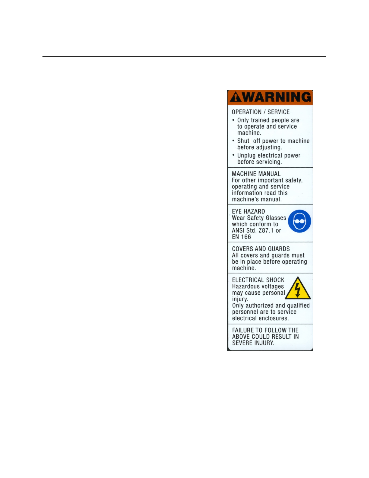
Important Safeguards
The illustrated label “WARNING - OPERATION /
SERVICE”, shown in Figure 6 is located on the side of the
column. This label provides convenient safety instruction for
the operator and service personnel in the operation of the
Interpack Carton Sealing Equipment.
F
Figure 6

UDM108-01 9 RSA2024-TB/2”
Specifications
1. Power Requirements:
Electrical - 115 VAC, 60 HZ, 8.4 A (966 Watts)
This machine comes standard with one (1) 1/6 H.P. and one (1) 1/3 H.P. gear motors and
comes with a standard neoprene covered power cord and a grounded plug. Contact your
Intertape Representative for power requirements not listed above.
2. Operating Speed:
Actual production rate is dependent on operator’s efficiency and the case size mix. Belt
speed is 82’ per minute

UDM108-01 10 RSA2024-TB/2”
Specifications
3. Operating Conditions:
Use in a dry, relatively clean environment at 40to 105F ( 5to 40C) with clean dry
cartons.
IMPORTANT NOTE:
MACHINE SHOULD NOT BE WASHED DOWN OR SUBJECTED TO
CONDITIONS CAUSING CONDENSATION ON COMPONENTS.
4. Tape:
Intertape brand Pressure Sensitive Carton Sealing Tape.
5. Tape Width:
Model RSA2024-TB/2” : 1 ½ inches (36 mm) to 2 inches (48 mm) maximum.
6. Tape Roll Diameter:
Up to 16 inches (405 mm) maximum on a 2 inch (48 mm) diameter core.
(Accommodates all Intertape brand film tape machine roll lengths)
7. Tape Application Leg length - Standard:
2 ½ inches (+1/4”, -0") (63.5 mm, + 6.3 mm, - 0 mm)
8. Tape Application Leg Length - Optional:
2 inches (+1/4”, -0”) ( 50.8 mm, + 6.3 mm, - 0 mm
NOTE: FOR FURTHER SPECIFICATIONS ON HSD®2000 TAPE HEADS,
CONSULT THE HSD®2000 ET II TAPE HEAD MANUAL PROVIDED WITH
THIS MACHINE.

UDM108-01 11 RSA2024-TB/2”
Specifications(Cont’d)
9. Box Board:
Style: regular slotted Containers (RSC)
125 to 275 P.S.I. bursting test, single or double wall B or C flute.
10. Carton Size Capacities:
Height (inches) Width (inches) Length (inches)
Standard
minimum 5 6 6
maximum 24 20 Infinite
Height (inches) Width (inches) Length (inches)
Optional
minimum 2 6 6
maximum 21 20 Infinite
Height (inches) Width (inches) Length (inches)
Optional
minimum 2 8 8
maximum 21 22 Infinite
UDM108-01 12 RSA2024-TB/2”
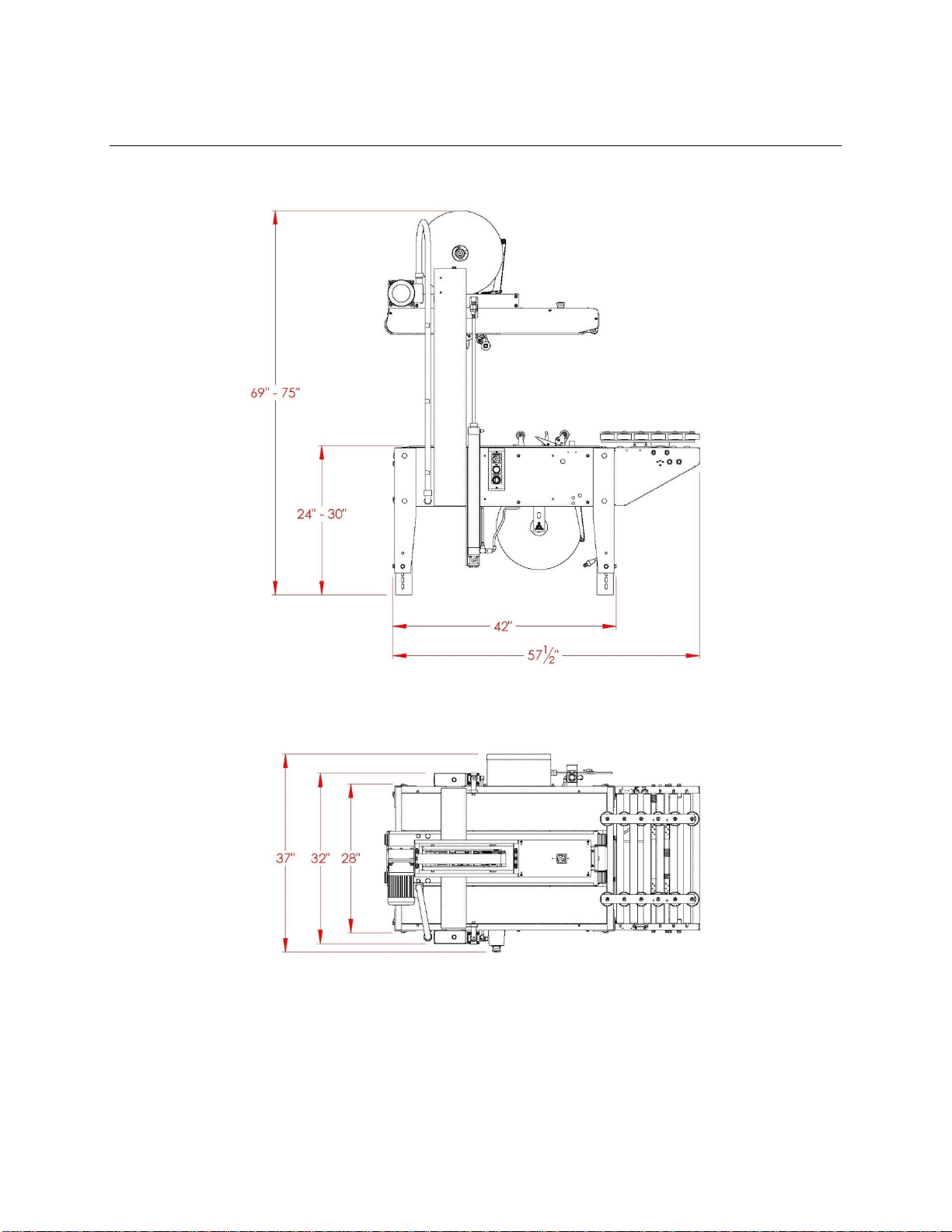
Specifications(Cont’d)
11. Machine Dimensions:
12. Set-Up Recommendations:
The Carton Sealer must be level.
Customer supplied infeed conveyor (if used) should provide straight and level entry.
Customer supplied exit conveyor (if used) should be straight and declined no more
than ¼”/foot away from the machine to convey the sealed cartons away from the
machine.
Figure 7

UDM108-01 13 RSA2024-TB/2”
Set-Up Procedure
Receiving and Handling
After unpacking the machine, look for any damage that may have occurred during shipping.
Should the machine be damaged, file a claim with the transport company and notify your
representative as soon as possible.
The following instructions are presented in the order recommended for setting up and installing
the RSA 2024-TB Carton Sealing machine as well as for learning the operating functions and
adjustments. Following them step by step will result in your thorough understanding of the
machine and an installation in your production line that best utilizes the many features built into
the carton sealer.
1. Lift off cover and sleeve after removing the strapping and staples at bottom.
2. Remove mounting bolts and nuts, which secure the RSA 2024-TB to the shipping pallet
4. Lift machine off pallet and install on your packaging line.
5. Ensure that the machine is level and firmly on the ground (no rocking). Note that the
machines’ roller height can be adjusted with the four (4) adjustment legs to accommodate
conveyor heights from 23 ½" to 29 ½". To adjust the carton sealer, block the machine to
allow adequate leg adjustment. Using a 9/16" box end wrench, loosen and remove the
eight (8) 3/8 hex head bolts, adjust the legs to the desired conveyor height and reinstall
the bolts.
6. Customer supplied infeed and exit conveyors (or rollers) must be level with the machine,
otherwise, the performance of the machine may be affected.
Note: The exit conveyor either gravity fed or driven should be installed with
no more than 1/4" per foot decline.
UDM108-01 14 RSA2024-TB/2”
Set-Up Procedure
Table Level
The Carton Sealer must be installed on a near level ground.
Ensure that the machine is level and firmly on the ground (no rocking). Adjust the roller height
with the four (4) telescopic adjustment legs to accommodate conveyor heights from 24 to 30
inches.
To adjust the Carton Sealer height,
jack up the machine to give ample
room to extend the legs. Using a
3/4" (19 mm) box end wrench, loosen
the eight (8) M10 hex head bolts.
Adjust the legs to the desired
conveyor height and tighten the
bolts. Etched lines on the legs ease
leveling.
Customer supplied infeed and exit conveyors (or rollers) must be level with the machine,
otherwise, the performance of the machine may be affected. The customer-supplied infeed
conveyor (if used) should provide straight and level entry. The customer-supplied exit conveyor
(if used) should be straight and declined no more than 1/4 inch per foot away from the machine.
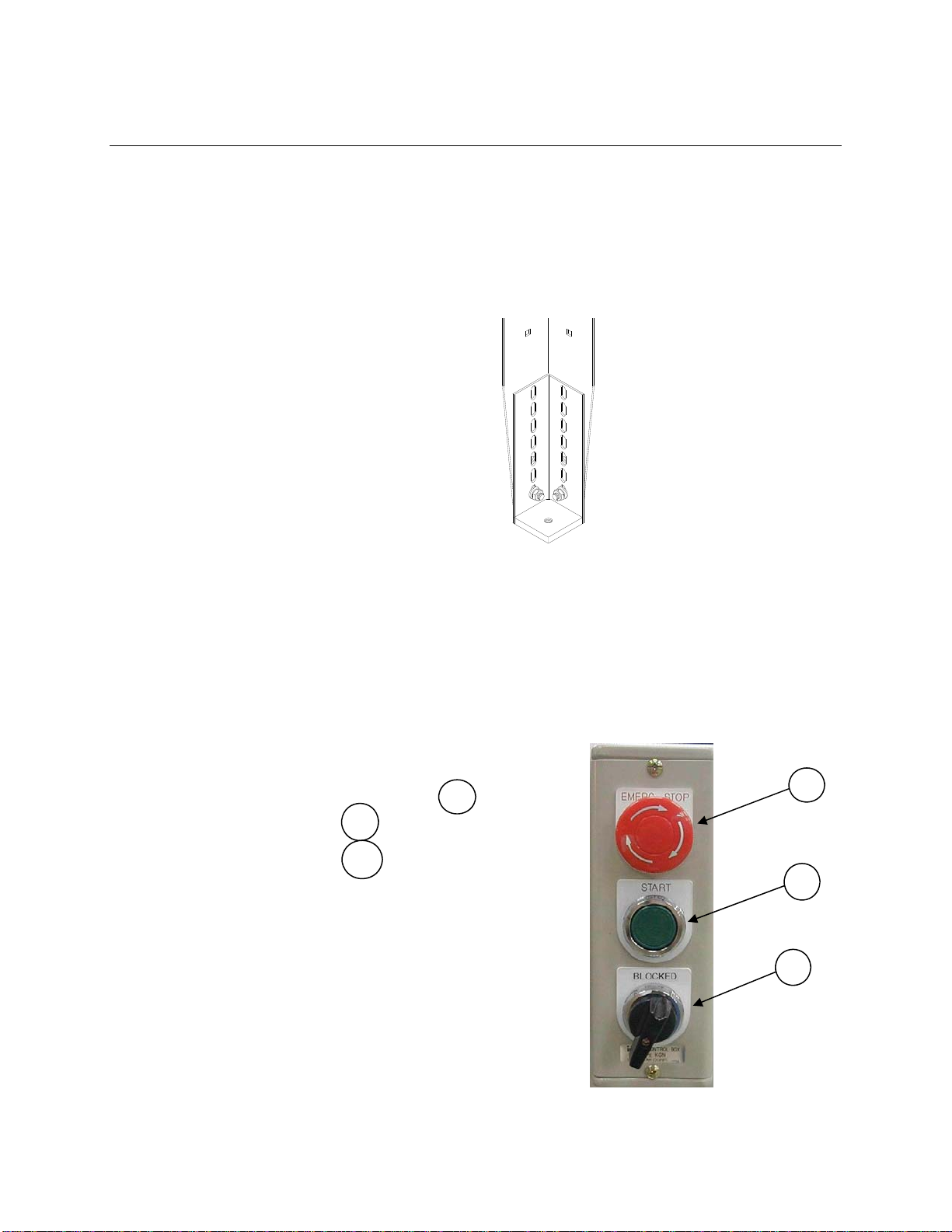
Stop/Start Box
The Stop/Start Box contains :
the red "E-STOP" mushroom push button,
the green "ON" push button,
and the “BLOCKED” button.
The E-Stop is a detented type, when it is pushed
down, it will stay in the down position. In order to
re-start the machine, the operator has to pull up the
E-Stop button and press on the green "on" push
button.
1
2
3
3
1
2
Figure 8
Figure 9

UDM108-01 15 RSA2024-TB/2”
Set-Up Procedure
Tape Loading
The HSD®2000-ET II /2’’Tape Heads accommodate 2" wide Tape rolls and HSD®2000-ET II
/3’’Tape Heads accommodate 3" wide rolls. Check the Tape Head Manual included with your
Carton Sealer or the Tape Head label on the side of the HSD®2000 ET II Tape Head to
determine which Tape Head you are using. Push the roll of tape onto the Mandrel with the
adhesive side up (refer to Threading Diagram on the HSD® 2000 ET II tape head) until the
core seats against the Mandrel flange. This ensures the tape will be centered when feeding into
the tape head.

UDM108-01 16 RSA2024-TB/2”
Set-Up Procedure
Tape Threading - Upper Tape Head
Remove the blade guard from the knife in the Tape head. NOTE: TURN OFF ELECTRICAL
POWER SUPPLY AND DISCONNECT THE POWER CORD FROM THE
ELECTRICAL SUPPLY BEFORE BEGINNING TO WORK ON THE TAPE HEADS OR
TO LOAD TAPE. IF POWER CORDS ARE NOT DISCONNECTED, SEVERE INJURY
TO PERSONNEL COULD RESULT. THE KNIFE CONTAINED IN THE TAPE HEAD
IS EXTREMELY SHARP. USE CAUTION WHEN REMOVING THE BLADE GUARD
AND THREADING THE TAPE TO AVOID PERSONNEL INJURY. To thread the tape
into the Upper Tape Head you do not require any special tools. Pull approximately 12" of tape
from the roll and fold in half. This allows you to thread the tape without it adhering to the guide
and clutch rollers inside the tape head. Follow the Tape Threading Diagram on the side plate of
the HSD
®
2000 Tape Head. See your Tape Head manual for further information if required.
Tape Threading - Lower Tape Head
Lift Top tape Head Box to the uppermost position by activating the “BLOCKED” selector
switch on the control box. Remove the Lower tape Head by grasping the tape application rollers
and lifting straight up. Remove the blade guard from the knife in the Tape head. NOTE: THE
KNIFE CONTAINED IN THE TAPE HEAD IS EXTREMELY SHARP. USE CAUTION
WHEN REMOVING THE BLADE GUARD AND THREADING THE TAPE TO AVOID
PERSONNEL INJURY. To thread the tape into the Lower Tape Head you do not require any
special tools. Pull approximately 12" of tape from the roll and fold in half. This allows you to
thread the tape without it adhering to the guide and clutch rollers inside the tape head. Follow the
Tape threading diagram on the side plate of the HSD
®
2000 Tape Head. See your Tape Head
manual for further information if required. Replace the Lower tape head in the machine. Turn off
the “BLOCKED” selector switch.
Electrical Connection
A twelve (12) foot standard three conductor power cord with plug is provided for 115 V, 60 Hz,
15 amp electrical service. The servicing receptacle must be properly grounded. Before the
machine is plugged into the receptacle, ensure that all materials are removed from the machine.
Note: Use of an extension cord is not recommended because of voltage drop.
The electrical control is protected with an
automatic circuit breaker with re-settable
overload. This reset is located in the electrical
box in the lower left quadrant (Fig. 9). Push
on the blue button to reset.
Figure 10

UDM108-01 17 RSA2024-TB/2”
Air Connection
The regulator has a male "quick disconnect" adaptor. Connect clean dry compressed air to this
adapter. The RSA2024-TB requires a minimum of 3 C.F.M. at 75 psi maximum.
To regulate the air pressure, pull on the
green knob located on the side of the
machine. Turn the knob clockwise for
more pressure and counter clockwise for
less. When the air pressure is at 75 psi,
push back down on the button until a
"click" is felt. The threading size is 3/8
NPT.
Pneumatic Adjustment
The main air filter/regulator controls the air pressure going inside the machine. It also controls
the air pressure inside the cylinders that rise the Top Belt Drive Assembly and open the infeed
guides. The recommended pressure setting for the main air filter/regulator is between 60
and 70 PSI.
The Infeed Guide Pressure is controlled with the pressure regulator located at the infeed end of
the machine, under the left hand Side Cover (Item 24 on the Bottom Belt Drive Structural
drawing). By increasing the air pressure, you increase the centring force of the guides on the
box. The recommended pressure setting for the Infeed Guide regulator is between 30 and
40 PSI.
The weight of the Top Belt Drive Assembly on the box is controlled by the High Flow Pressure
Control located at the discharge end of the machine, under the left hand Side Cover. This
controls the air pressure at the bottom of the cylinder and counterbalance for the weight of the
Top Belt Drive Assembly. Therefore, to reduce the weight applied on the top of the box, you
have to increase the air pressure. . The recommended pressure setting for the High Flow
Pressure Control is between 35 and 45 PSI.
Figure 11

UDM108-01 18 RSA2024-TB/2”
Operating Instructions
Once the HSD®2000 Tape Heads, (both bottom and top) have been loaded with tape and
threaded the machine is ready to process RCS cartons. The following instructions are presented
in the order recommended for processing cartons successfully through the RSA 2024-TB
Carton Sealing machine.
1- Activate air Supply (3 C.F.M. at 80 P.S.I.).
2- Switch the machine on with start push button.
3- Place carton with flaps held in closed position on the Infeed Table up to sensor #1.(Item
45 or 49 on the “Infeed Table W/ Guide” drawing)) Sensor will detect carton and the
Infeed Guides will center the carton.
Warning:
Ensure that the operator’s hands are away from the contact area between the Infeed
Guides and the carton.
4- Push carton with flaps held in closed position against the Front Sensing Paddle at the
front of the Top Belt Drive Assembly. This will raise the Top Belt Drive Assembly. Push
the rear of the carton until it is between the top and bottom drive belts.
WARNING!!
Ensure That The Operator’s Hands Are Away From The Moving Belts Of The Top And
Bottom Drive Assemblies
5- When the carton exits the Carton Sealer, the Top Belt Drive Assembly will go down to
his initial position.
6- The Carton Sealer is now ready to process the next carton..

UDM108-01 19 RSA2024-TB/2”
Troubleshooting
Interpack Carton Sealers are fabricated with high quality components that provide trouble-free
operation for a long period. However, if a problem should occur we recommend that you always
look for simple things first, then more complex problems. This is exactly how this table is
constructed, as the numbers increase, complexity increases.
TROUBLE POSSIBLE CAUSES SOLUTIONS
The main power
is turned on and
nothing happens
1- One of the fuses is burned.
1- Verify all fuses in the electric
box.
The machine is
ON but the
Infeed Guides do
not center the
carton on the
Infeed Table.
1- Compressed air supply is not
connected.
2- The air tubing or the valve is
obstructed or defective.
1- Inspect air connection and
operating pressure
2- Inspect the air tubing and the
valve for leaks or obstructions.
The Infeed
Guides closes
when the
machine is
powered up even
when there is no
carton on the
Infeed Table.
1- The Infeed Table’s Sensor is
not aligned with his reflector. 1- Check the alignment of the
Infeed Sensor with his reflector.
The Top Belt
Drive Assembly
stays up or goes
down too slowly.
1- The High Flow Pressure
Regulator is adjusted too
high.
1- Reduce the air pressure setting
of the High Flow Pressure
Regulator, located at the infeed
end of the machine, under the
left hand Side Cover.
The Top Belt
Drive Assembly
goes down too
quickly or
crushes the
carton.
1- The High Flow Pressure
Regulator is adjusted too low. 1- Increase the air pressure setting
of the High Flow Pressure
Regulator, located at the infeed
end of the machine, under the
left hand Side Cover.

UDM108-01 20 RSA2024-TB/2”
The Top Belt
Drive Assembly
raises too slowly.
1- The inlet pressure is too low.
2- The moving parts are rubbing
on something.
1- Adjust the inlet pressure on the
main regulator to 80 psi and
make sure that the pressure
doesn't fall below 70 psi while
it is operating.
2- Inspect the Top Belt Drive
Assembly to make sure that
noting interferes with them.
The Top Belt
Drive Assembly
does not rise
when the carton
pushes the Front
Sensor Plate.
1- The Proxy Sensor behind the
sensor plate is too far from
the Front Sensor Plate.
1- Remove the Front Sensor Plate
and adjust the position of the
Proxy Sensor by moving it by
1/16”, then replace the Front
Sensor Plate and verify proper
operation. Make sure that the
sensor does not touch the Front
Sensor Plate.
The cartons are
not taped
properly.
1- The tape head is not adjusted
correctly 1- Refer to the tape head manual.
Table of contents
Other Interpack Food Saver manuals


