Interroll DL Series User manual

INSPIRED BY EFFICIENCY
User Manual
Interroll Drum motor
DL series

Manufacturer
Interroll Trommelmotoren GmbH Interroll Corporation
Opelstr. 3 3000 Corporate Drive
41836 Hueckelhoven/Baal Wilmington, NC 28405
Germany USA
Tel. +49 2433 44 610 Tel. +1 910 799-1100
www.interroll.com www.interroll.com
Interroll (Suzhou) Co. Ltd. Interroll Logistica Ltda.
No.16 Huipu Road Av. Vicenzo Granguelli, 856
Suzhou Industrial Park, Jiangsu Galpao Industrial N. 05
Province 215126, Suzhou 13916- 058 Jaguariuna SP
China Brazil
www.interroll-group.cn www.interroll.com
Interroll Canada Ltd.
1201 Gorham Street
Newmarket, ON L3Y 8Y2
Canada
www.interroll.com
Contents
We strive for the information presented to be correct, up to date and complete. We have carefully worked out the
contents of this document. However, we assume no liability for the information. We expressly deny any liability for
damages or consequential damages that are connected in any form with the use of this document. We reserve the
right to change the documented products and product information at any time.
Copyright / intellectual property right
Texts, images, graphics and the like as well as their arrangement are protected by copyright and other protection
laws. Reproduction, modication, transfer or publication of any part or the entire content of the document in any
form is prohibited. This document is intended exclusively for information purposes and for intended use and does not
authorize replicating the respective products. All signs contained in this document (registered trademarks, such as
logos and business designations) are the property of Interroll Trommelmotoren GmbH or third parties and may not be
used, copied or distributed without prior written consent.

Version 1.2 (08/2022) en
Translation of original operating instructions 3 of 64
Table of Contents
1 Information about the manual 6
2 Safety 7
2.1 State of the art...........................................................................................................................................................................7
2.2 Intended use................................................................................................................................................................................7
2.3 Unintended use...........................................................................................................................................................................7
2.4 Personnelqualication..............................................................................................................................................................7
2.5 Dangers........................................................................................................................................................................................8
2.6 Interfaces to other devices......................................................................................................................................................9
3 General technical information 10
3.1 Product description................................................................................................................................................................. 10
3.1.1 Options................................................................................................................................................................ 10
3.2 Dimensions of DL series drum motor................................................................................................................................. 10
3.3 Technical data.......................................................................................................................................................................... 12
3.4 Productidentication............................................................................................................................................................. 12
3.5 Thermal protection................................................................................................................................................................. 13
4 Product information of DL series asynchronous 1-phase 14
4.1 Type plate of DL series asynchronous 1-phase.............................................................................................................. 14
4.2 Electrical data for DL series asynchronous 1-phase ..................................................................................................... 16
4.2.1 DL 0080 asynchronous 1-phase................................................................................................................... 16
4.2.2 DL 0113 asynchronous 1-phase................................................................................................................... 17
4.3 Connection diagrams of DL series asynchronous 1-phase ......................................................................................... 17
4.3.1 Cable connections............................................................................................................................................. 17
4.3.2 Connections in the terminal box ................................................................................................................... 18
5 Product information of DL series asynchronous 3-phase 19
5.1 Type plate of DL series asynchronous 3-phase.............................................................................................................. 19
5.2 Electrical data for DL series asynchronous 3-phase ..................................................................................................... 21
5.2.1 DL 0080 asynchronous 3-phase................................................................................................................... 21
5.2.2 DL 0113 asynchronous 3-phase................................................................................................................... 22
5.3 Connection diagrams of DM series asynchronous 3-phase ....................................................................................... 23
5.3.1 Cable connections............................................................................................................................................. 23
5.3.2 Connections in the terminal box ................................................................................................................... 25
6 Options and accessories 26
6.1 Asynchronous drum motors with frequency inverters .................................................................................................. 26
6.1.1 Torque depends on input frequency............................................................................................................ 26
6.1.2 Frequency inverter parameters..................................................................................................................... 26
7 Transport and storage 28
7.1 Transport ................................................................................................................................................................................... 28
7.2 Storage...................................................................................................................................................................................... 29

4 of 64
Version 1.2 (08/2022) en
Translation of original operating instructions
Table of Contents
8 Assembly and installation 30
8.1 Warning notices concerning the installation ................................................................................................................... 30
8.2 Installing the drum motor ..................................................................................................................................................... 30
8.2.1 Positioning the drum motor............................................................................................................................. 30
8.2.2 Installing the motor with mounting brackets.............................................................................................. 31
8.3 Belt assembly ........................................................................................................................................................................... 33
8.3.1 Belt adjustment................................................................................................................................................... 33
8.3.2 Tensioning the belt ............................................................................................................................................ 34
8.4 Belt tension ............................................................................................................................................................................... 35
8.4.1 Belt elongation................................................................................................................................................... 35
8.4.2 Measuring the belt elongation ...................................................................................................................... 36
8.4.3 Calculating the belt elongation..................................................................................................................... 37
8.5 Drum coating ........................................................................................................................................................................... 38
8.6 Sprockets .................................................................................................................................................................................. 38
8.7 Warning notices concerning the electrical installation ................................................................................................. 38
8.8 Electrical connection of the drum motor .......................................................................................................................... 39
8.8.1 Connecting the drum motor – with a cable .............................................................................................. 39
8.8.2 Connecting the drum motor – with a terminal box................................................................................. 39
8.8.3 Single-phase motor .......................................................................................................................................... 39
8.8.4 External motor protection............................................................................................................................... 39
8.8.5 Integrated thermal protection ....................................................................................................................... 40
8.8.6 Frequency inverter............................................................................................................................................ 40
9 Initial startup and operation 42
9.1 Initial startup ............................................................................................................................................................................ 42
9.1.1 Checks before the initial startup................................................................................................................... 42
9.2 Operation................................................................................................................................................................................. 42
9.2.1 Checks before every startup.......................................................................................................................... 43
9.3 Procedure in case of accident or fault.............................................................................................................................. 43
10 Maintenance and cleaning 44
10.1 Warning notices concerning maintenance and cleaning............................................................................................. 44
10.2 Preparation for maintenance and cleaning by hand....................................................................................................44
10.3 Maintenance ............................................................................................................................................................................ 44
10.3.1 Checking the drum motor............................................................................................................................... 44
10.3.2 Relubricating the drum motor........................................................................................................................ 44
10.3.3 Maintaining drum motors with optional, relubricating IP66 seals....................................................... 45
10.4 Oil change at drum motor................................................................................................................................................... 45
10.5 Cleaning.................................................................................................................................................................................... 45
10.5.1 Cleaning the drum motor with pressure washer...................................................................................... 46

Version 1.2 (08/2022) en
Translation of original operating instructions 5 of 64
Table of Contents
10.5.2 Hygienic cleaning.............................................................................................................................................. 47
11 Troubleshooting 48
12 Decommissioning and disposal 55
12.1 Shutdown.................................................................................................................................................................................. 55
12.2 Disposal..................................................................................................................................................................................... 55
13 Appendix 56
13.1 List of abbreviations............................................................................................................................................................... 56
13.2 Translation of the original Declaration of Conformity (CE)......................................................................................... 59
13.3 Translation of the original Declaration of Conformity (UKCA) .................................................................................. 60

6 of 64
Version 1.2 (08/2022) en
Translation of original operating instructions
Information about the manual
1 Information about the manual
In this instruction manual, the following drum motor types are described:
• DL series
Contents
This instruction manual contains important notes and information about the various operating phases of the drum
motor:
The instruction manual describes the drum motor as it is delivered by Interroll.
In addition to this instruction manual, special contractual agreements and technical documents apply to special
versions.
The instruction manual is part of the product
• Fortrouble-free,safeoperationandwarrantyclaims,readtheinstructionmanualrstandfollowtheinstructions.
• Keep the instruction manual close to the drum motor.
• Pass the instruction manual on to any subsequent operator or occupant.
• NOTICE! The manufacturer does not accept any liability for faults or defects due to non-observance of this
instruction manual.
• If you still have questions after reading the instruction manual, please contact Interroll customer service. Contact
persons close to you can be found on the Internet under www.interroll.com.

Version 1.2 (08/2022) en
Translation of original operating instructions 7 of 64
Safety
2 Safety
2.1 State of the art
The conveyor is designed according to the state of the art and is reliable in operation, once distributed. However, risks
may still arise.
Disregarding the notices in this manual may lead to serious injury.
• Carefully read the manual and follow its content.
• Observe local accident prevention regulations and general safety regulations that apply in the area of use.
2.2 Intended use
The drum motor is intended for use in industrial environments, supermarkets and airports and is used for transporting
general cargo, such as parts, cardboard boxes or boxes, as well as transporting bulk material such as granular
material,powderandotheruidmaterials.Thedrummotormustbeintegratedintoaconveyormoduleorconveyor
system. Any other use is considered inappropriate.
Useofthedrummotorisonlyallowedintheareasdescribedintheproductinformationchapter.Anymodications
thataectthesafetyoftheproductarenotpermitted.
Thedrummotormayonlybeoperatedwithinthedenedoperatinglimits.
2.3 Unintended use
The drum motor must not be used for transporting people.
The drum motor is not intended for use under impact or shock loads.
The drum motor is not designed to be used under water. Such a use leads to personal or fatal injuries from
electrocution as well as the penetration of water, resulting in a short circuit or motor damage.
The drum motor may not be used in an explosive atmosphere.
The drum motor may not be used as a drive for cranes or lifting devices or for the corresponding hoist ropes, cables
or chains.
Use of the drum motor for anything other than the intended purpose is subject to approval by Interroll.
Unlessotherwisestatedinwritingand/orspeciedinaquote,Interrollanditsdealersshallassumenoliabilityfor
productdamageorfailurewhichresultfromfailuretoobservethesespecicationandrestrictions(seethechapter
„Electrical data” of the respective series).
2.4 Personnel qualication
Unqualiedpersonnelcannotrecognizerisksand,asaresult,issubjecttogreaterdangers.
• Authorizeonlyqualiedpersonneltoperformtheactivitiesdescribedintheseinstructions.
• The operating company must ensure that personnel follow locally applicable regulations and rules about safety and
hazardswhileworking.
The following target groups are addressed in these instructions:

8 of 64
Version 1.2 (08/2022) en
Translation of original operating instructions
Safety
Operators
Operators have been instructed in operating and cleaning the drum motor and follow the safety guidelines.
Service personnel
The service personnel features a technical training or has undergone training by the manufacturer and performs the
maintenance and repair tasks.
Electricians
Persons working on electrical installations must have pertinent technical training.
2.5 Dangers
The following list informs you about the various types of danger or damage that may occur while working with the
drum motor.
Bodily injury
• Maintenanceorrepairworkondrummotorsmustonlybeperformedbyauthorizedservicepersonsinaccordance
with applicable regulations.
• Beforeturningonthedrummotor,ensurethatnounauthorizedpersonsareneartheconveyor
Electricity
Performanyinstallationandmaintenancetasksonlyafterfollowingthevesafetyrules:
• Disconnect
• Secure against reactivation
• Determinede-energizedstateatallpoles
• Ground and short circuit
• Cover or block neighboring live parts
Oil
• Do not ingest the oil. The oil used may contain harmful substances. Ingestion can lead to nausea, vomiting and/or
diarrhea. If oil is ingested, immediately seek medical assistance.
• Avoid contact with skin and eyes. Prolonged or repeated contact with skin without proper cleaning can clog the
pores of the skin and lead to skin problems such as oil acne and folliculitis.
• Wipe up spilled oil as quickly as possible to avoid slippery surfaces. Ensure that oil does not reach the environment.
Properlydisposeofdirtyragsorcleaningmaterialstoavoidself-ignitionandres.
• Extinguishoilreswithfoam,sprayingwaterorwatermist,drychemicalpowderorcarbondioxide.Donot
extinguish with a water jet. Wear suitable protective clothing, incl. breathing mask.
• Observethecorrespondingcerticatesatwww.interroll.com.

Version 1.2 (08/2022) en
Translation of original operating instructions 9 of 64
Safety
Rotating parts
• Do not reach into areas between drum motor and conveyor belts or roller chains.
• Tie long hair together.
• Never wear loose clothing.
• Never wear jewelery, such as necklaces or bracelets.
Hot motor parts
• Do not touch the surface of the drum motor. It can result in burns, even under regular operating temperature.
• Install corresponding warnings on the conveyor.
Working environment
• Do not use the drum motor in explosive atmospheres.
• Remove equipment or material which is not required from the workspace.
• Wear safety shoes.
• Clearly specify and monitor the way materials are placed on the conveyor.
Faults during operation
• Regularly check the drum motor for visible damage.
• In case of fumes, unusual noise or blocked or damaged materials, stop the drum motor at once and ensure that the
RollerDrive cannot be started accidentally.
• Contactqualiedpersonnelimmediatelytondthesourceofthefault.
• During operation, do not step on the drum motor or the conveyor/the system in which it is installed.
Maintenance
• Checktheproductregularlyforvisibledamages,unusualnoiseandrmseatingofttings,screwsandnuts.An
additional maintenance is not required.
• Do not open the drum motor.
Accidental motor start
• Take care during installation, maintenance work and cleaning or in the event of a drum motor fault: The drum
motor could start up unintentionally.
2.6 Interfaces to other devices
Hazardsmayoccurwhileintegratingthedrummotorintoacompletesystem.Thesearenotpartofthismanualand
havetobeanalyzedduringthedesign,installationandstartupofthecompletesystem.
• After assembling the drum motor in a conveyor module, check the whole system for a new potential dangerous
spot before switching on the conveyor.
• Additional constructive measures may be required.

10 of 64
Version 1.2 (08/2022) en
Translation of original operating instructions
General technical information
3 General technical information
3.1 Product description
The drum motor is a completely enclosed electrical drive roller. It replaces external components such as motors and
gears, which require frequent maintenance.
Thedrummotorcanbeusedinenvironmentswithhighcoarseandnedustexposureaswellasexposedtowaterjets
and spraying water and is resistant to most aggressive ambient conditions. In harsh environments and environments
with salt water, only stainless steel motors should be used. Thanks to its protection rating of IP66 and its stainless steel
design (upon request), the drum motor is also suitable for use in the food processing and pharmaceutical industries, as
well as for applications with high hygienic demands. The drum motor can be used with or without a drum coating to
increasefrictionbetweendrummotorandconveyorbelt,orwithaprolecoatingtodriveform-tdrivenbelts.
DL series drum motors are driven by an asynchronous three-phase induction motor. That motor is available at
dierentpowerlevelsandformostinternationalsupplyvoltages.
The drum motor contains oil as lubricant and coolant which dissipates the heat via the drum shell and the conveyor
belt.
3.1.1 Options
Integrated thermal overload protection
A thermal circuit breaker integrated in the winding head protects against overheating. The switch trips if the motor
overheats. However, it must be connected to a suitable external control device that interrupts the power supply to the
motor in case of overheating.
3.2 Dimensions of DL series drum motor
Some dimensions are listed as „FW+”. FW is the abbreviation for „Face Width” (drum width). This information is
located on the type plate of the drum motor.
All length-related dimensions in the catalog and in these operating instructions comply with the requirements of DIN/
ISO 2768 (medium quality).
The recommended distance between the mounting brackets (EL) while taking into account the maximum
thermal expansion and internal tolerances is EL + 2 mm.

Version 1.2 (08/2022) en
Translation of original operating instructions 11 of 64
General technical information
Dimensions of DL series drum motor
Type A
mm
B
mm
C
mm
D
mm
E
mm
F
mm
P
mm
SL
mm
EL
mm
AGL
mm
DL 0080 crowned
SL 260 to 602 mm
81,5 80 20 35 3 21 5 FW-10 FW+6 FW+46
DL 0080 crowned, mild steel
shell,
SL 603 to 952 mm
82,7 81 20 35 3 21 5 FW-10 FW+6 FW+46
crowned, stainless steel shell,
SL 603 to 952 mm
83 80 20 35 3 21 5 FW-10 FW+6 FW+46
DL 0080 cylindrical
SL 260 to 602 mm
80,5 80,5 20 35 3 21 5 FW-10 FW+6 FW+46
DL 0080 cylindrical, mild steel
shell,
SL 603 to 952 mm
82,7 82,7 20 35 3 21 5 FW-10 FW+6 FW+46
DL 0080 cylindrical, stainless
steel shell,
SL 603 to 952 mm
83 83 20 35 3 21 5 FW-10 FW+6 FW+46
DL 0113 crowned 113,3 112,4 20 35 3 21 11 FW-22 FW+6 FW+46
DL 0113 cylindrical 113,0 113,0 20 35 3 21 11 FW-22 FW+6 FW+46
DL 0113 cylindrical
SL 1091 to 2450 mm
114,3 114,3 20 35 3 21 11 FW-22 FW+6 FW+46

12 of 64
Version 1.2 (08/2022) en
Translation of original operating instructions
General technical information
3.3 Technical data
Protection class IP66
Ambient temperature range for standard applications 1) +5 °C to +40 °C
Ambient temperature range for low-temperature
applications 1)
-25 °C to +15 °C
Ambient temperature range for reduced drum motors +5 °C to +25 °C
Ramp times DLseries:≥1s
Installation altitude above sea level max. 1000 m
1) For ambient temperatures below +1 °C, Interroll recommends anti-condensation heating and special cables or
plastic terminal boxes.
3.4 Product identication
Theserialnumberissucienttoidentifyadrummotor.Asanalternative,theinformationlistedbelowisrequired.The
valuesforaspecicdrummotorcanbeenteredinthelastcolumn.
Information Possible value Own value
Type plate of drum motor Motor type and design:
Circumferential speed vN:
Diameter of tube ø:
FW drum width:
Number of poles np:
Rated power PN:
Drum design (tube design) e.g. Drum material
Coatingtype(color,material,prole,grooves)
End cover Material
Features deviating from the standard
Shafts Material
Features deviating from the standard

Version 1.2 (08/2022) en
Translation of original operating instructions 13 of 64
General technical information
3.5 Thermal protection
Under normal operating conditions, the thermal circuit breaker integrated in the stator winding is closed. When the
motor limit temperature is reached (overheating), the switch opens at a preset temperature to prevent damage to the
motor.
WARNING
The thermal circuit breaker is automatically reset after the motor has cooled o.
Inadvertent start-up of the motor
¾Connect the thermal circuit breaker in series with a suitable relay or contactor so that the current supply to
the motor is safely interrupted when the switch trips.
¾Ensurethatthemotorcanbeswitchedonagainafteroverheatingonlywithaconrmationbutton.
¾Aftertheswitchhastripped,waituntilthemotorhascooledo,andensurepriortoswitch-onthatthereis
no danger to persons.
Standard design: temperature limiter, automatically switching back
Service life: 10.000 cycles
AC cos φ = 1 2,5 A 250 V AC
cos φ = 0,6 1,6 A 250 V AC
DC 1,6 A 24 V DC
1,25 A 48 V DC
Service life: 2.000 cycles
AC cos φ = 1 6,3 A 250 V AC
Reset temperature 40 K ± 15 K
Resistance <50mΩ
Contact bounce time < 1 ms
14 of 64
Version 1.2 (08/2022) en
Translation of original operating instructions
Product information of DL series asynchronous 1-phase
4 Product information of DL series asynchronous 1-phase
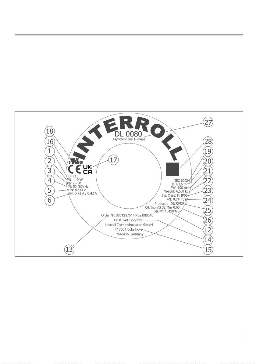
4.1 Type plate of DL series asynchronous 1-phase
The information on the type plate of the drum motor is used to identify it. This is the only way for the drum motor to
be used properly.
DrummotorsoftheDLserieshavedierentkindsoftypeplates:
1. Round type plate (1) on the end cover of the drum motor (glued or laser-engraved)
2. Rectangular type plate (2) on the terminal box (if available, glued or laser-engraved)
3. Rectangular type plate (3) included with the motor
Type plate (1) for DL series asynchronous 1-phase
Version 1.2 (08/2022) en
Translation of original operating instructions 15 of 64
Product information of DL series asynchronous 1-phase
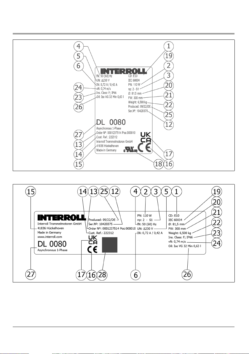
Type plate (2) for DL series asynchronous 1-phase
Type plate (3) for DL series asynchronous 1-phase

16 of 64
Version 1.2 (08/2022) en
Translation of original operating instructions
Product information of DL series asynchronous 1-phase
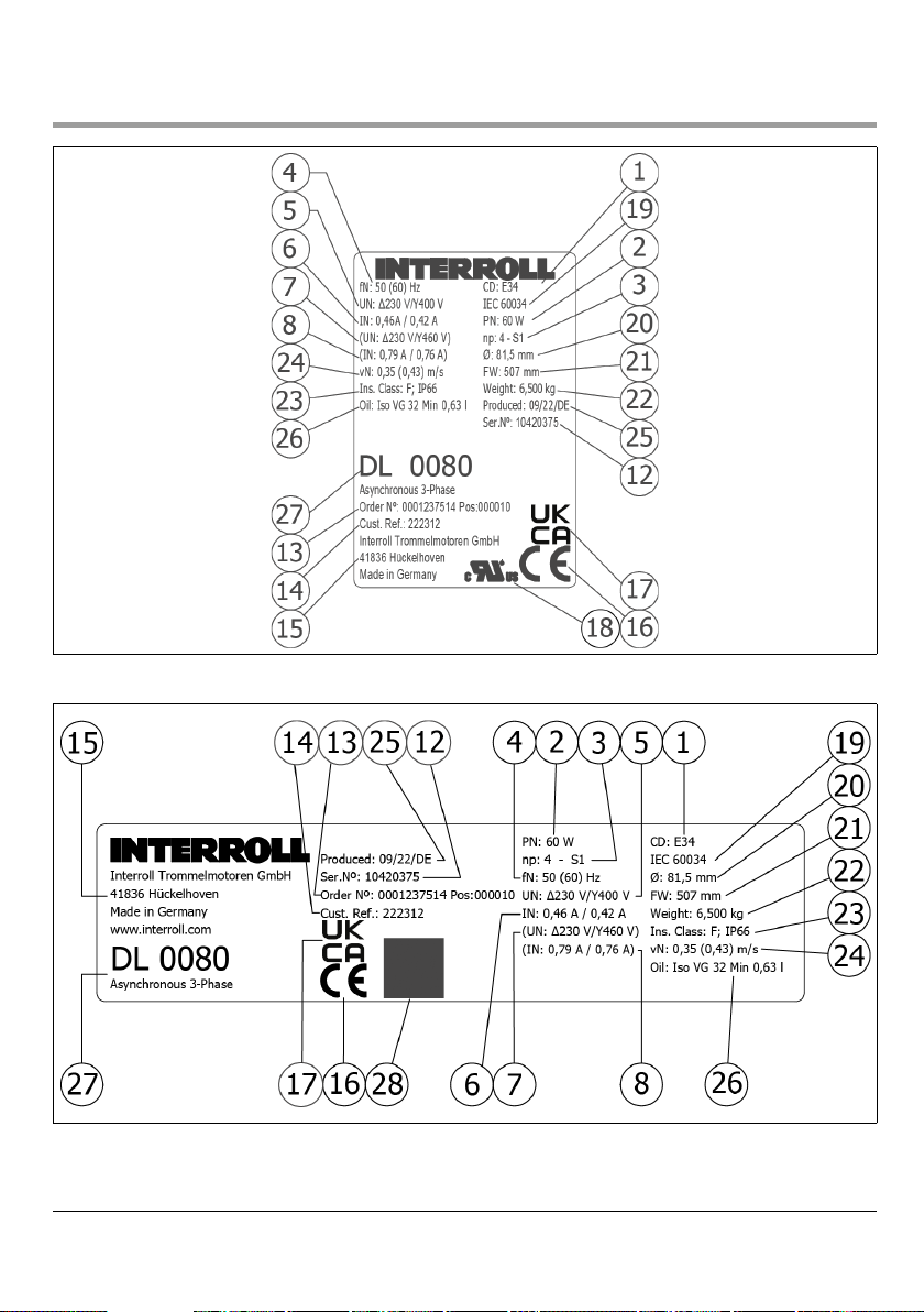
1 Connection diagram number 18 UL mark
2 Rated power 19 International Electrotechnical Commission: Standard
for drum motors
3 Number of poles + operating mode 20 Drum tube diameter
4 Rated frequency 1) 21 Drum width
5 Rated voltage at rated frequency 22 Weight
6 Rated current at rated frequency 23 Insulation class and protection rate
12 Serial number 24 Circumferential speed of drum tube 1)
13 Order number + item 25 Manufactured week/year/country
14 Customer item number 26 Oil type and quantity
15 Manufacturer's address 27 Type + design
16 CE mark 28 QR code
17 UKCA mark
1) The value depends on the voltage used. All values in parentheses refer to the rated voltage in parentheses.
4.2 Electrical data for DL series asynchronous 1-phase
Abbreviations see page 56.
4.2.1 DL 0080 asynchronous 1-phase
PN nPnNfNUNINcos
φ
ηJRIS/INMS/
MN
MB/
MN
MP/
MN
MNRMUSH ~ CR
W min-1 Hz V A kgcm2Nm Ω VDC µF
25 4 1320 50 230 0,39 1 0,28 1,3 2,19 1,11 1,37 1,11 0,18 150 44 3
50 2 2750 50 230 0,54 1 0,4 0,9 3,08 0,94 1,71 0,94 0,17 82 33 3
75 2 2750 50 230 0,68 1 0,48 1 3,19 0,74 1,37 0,74 0,26 66 34 4
75 2 3300 60 230 0,68 1 0,48 1,3 4,89 1 1,83 1 0,22 38 19 6
85 2 2750 50 230 0,73 0,98 0,52 0,89 2,50 0,88 1,77 0,88 0,3 52 28 6
110 2 2750 50 230 0,94 1 0,51 1,3 1,97 0,73 1,15 0,73 0,38 51 36 8

Version 1.2 (08/2022) en
Translation of original operating instructions 17 of 64
Product information of DL series asynchronous 1-phase
4.2.2 DL 0113 asynchronous 1-phase
PN nPnNfNUNINcos
φ
ηJRIS/INMS/
MN
MB/
MN
MP/
MN
MNRMUSH ~ CR
W min-1 Hz V A kgcm2Nm VDC µF
60 4 1300 50 230 0,75 0,98 0,35 2,3 2,58 1,29 2,6 1,29 0,44 63,5 35 4
60 4 1560 60 230 0,86 0,98 0,31 2,3 2,58 1,29 2,6 1,29 0,37 63,5 40 4
90 4 1300 50 230 0,99 0,91 0,43 2,3 2,42 1,24 2,42 1,24 0,66 42,5 29 6
90 4 1560 60 230 1,1 0,91 0,39 2,3 2,42 1,24 2,42 1,24 0,55 42,5 34 6
110 4 1300 50 230 1,04 0,88 0,52 3,3 2,93 1,06 2,31 1,06 0,81 32,5 22 6
110 4 1560 60 115 2,15 0,94 0,47 3,3 3,24 1,08 2,8 1,08 0,67 6,3 10 20
110 4 1560 60 115 2,2 0,88 0,49 3,3 3,24 1,08 2,8 1,08 0,67 6,3 9 16
110 4 1560 60 230 1,18 0,88 0,46 3,3 2,93 1,06 2,31 1,06 0,67 32,5 25 6
150 4 1600 60 115 2,8 0,89 0,52 4 2,57 1,04 2,99 1,04 0,90 4 7 25
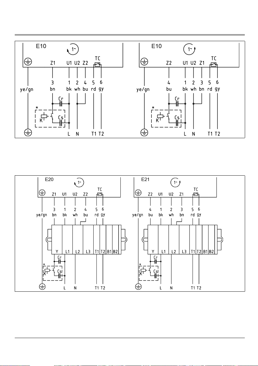
4.3 Connection diagrams of DL series asynchronous 1-phase
This instruction manual lists only standard connection diagrams. For other connection types, the connection diagram is
supplied separately with the drum motor.
Abbreviations see page 56.
4.3.1 Cable connections
1-phase, 6-core cable
* A starting capacitor and a matching switching relay can be connected as an option to improve the starting torque
of the single-phase motor.
18 of 64
Version 1.2 (08/2022) en
Translation of original operating instructions
Product information of DL series asynchronous 1-phase
1-phase, 7-core cable
* A starting capacitor and a matching switching relay can be connected as an option to improve the starting torque
of the single-phase motor.
4.3.2 Connections in the terminal box
1-phase, 7-core cable
* A starting capacitor and a matching switching relay can be connected as an option to improve the starting torque
of the single-phase motor.
Maximum torque for terminal box cover screws: 1.5 Nm

Version 1.2 (08/2022) en
Translation of original operating instructions 19 of 64
Product information of DL series asynchronous 3-phase
5 Product information of DL series asynchronous 3-phase
5.1 Type plate of DL series asynchronous 3-phase
The information on the nameplate of the drum motor is used to identify it. This is the only way for the drum motor to
be used properly.
DrummotorsoftheDLserieshavedierentkindsofnameplates:
1. Round nameplate (1) on the end housing of the drum motor (glued or laser-engraved)
2. Rectangular nameplate (2) on the terminal box (if available, glued or laser-engraved)
3. Rectangular nameplate (3) included with the motor
Type plate (1) for DL series asynchronous 3-phase
20 of 64
Version 1.2 (08/2022) en
Translation of original operating instructions
Product information of DL series asynchronous 3-phase
Type plate (2) for DL series asynchronous 3-phase
Type plate (3) for DL series asynchronous 3-phase
Table of contents
Other Interroll Industrial Equipment manuals


