U-Line Newair Instant Bubble Flex Machine User manual

PAGE 1 OF 30 0318 IH-7259
πH-7259
NEWAIR INSTANT
BUBBLE FLEX™MACHINE
1-800-295-5510
uline.com
SAFETY
BEFORE OPERATING THIS MACHINE:
1. Read and thoroughly understand this guide.
2. Read and understand all safety instruction labels
attached to machine.
3. Be sure the machine is plugged into a properly
rated, grounded outlet.
WARNING! Failure to properly ground the
system could create an electrical shock
hazard.
WARNING! Do not remove the guards or access
covers.
WARNING! Risk of entrapment. Keep fingers,
loose hair, clothing and jewelry away from
the edge seal roller when material is feeding,
inflating and sealing.
WARNING! Hot Surface. Edge seal roller will
become hot during use.
WARNING! Do not use bubble material as a
flotation device, toy or pillow.
NOTE: User must set up and select film type
before first usage. See Film Code Settings on
page 5.
4. Inspect at regular intervals to ensure that:
• Component cables are not cut, broken or
damaged.
• All controls and indicators function properly.
5. Airborne Noise Emission:
• This machine does not exceed 80 decibels during
normal operation. Please check to make sure
you comply with your local health and safety
requirements.
6. Environmental Conditions:
• Storage temperature:
Machine and material rolls – 32˚-110˚F.
• Operating temperature:
Machine and material rolls – 60˚-110˚F.
5/32" Allen Wrench
TOOL NEEDED
Para Español, vea páginas 11-20.
Pour le français, consulter les pages 21-30.

PAGE 2 OF 30 0318 IH-7259
OVERVIEW
SYSTEM COMPONENTS
SYSTEM DESCRIPTION
The H-7259 Instant Bubble Roll Machine creates
on-demand, air-filled cushioning material from a
compact/uninflated pre-formed roll of material. The
inflated material chain is perforated into sections and
can easily be separated by the operator as needed.
There are three modes of operation:
MANUAL MODE
• Press start key to begin producing material and the
stop key to end production.
BATCH MODE
• Dispense a programmed length of material.
ROLL WINDER MODE
• Requires optional roll winder (H-7283) and stand
(H-7284).
• Dispense a roll of inflated material.
ELECTRICAL POWER REQUIREMENTS
WARNING! Use of extension cord will increase
the levels of static, resulting in operational
problems.
Inflatable Cushioning System: 115 VAC
Receptacle Type: NEMA 5-15R
A/C Voltage: 100-120 VAC 50/60 Hz
Phase: Single Phase Grounded
Current: 15A Service 4.0A
NOTE: The use of non-compatible materials will
cause production problems, may damage the
equipment and will reduce the quality of the
packaging protection.
1. ON/OFF Power Switch
Switch controls power to system and is located on
back of machine.
2. Emergency Stop Switch (E-Stop)
Switch stops all feeding, inflating and sealing functions.
3. Main Power Cord
Plug into a properly rated receptacle. See Electrical
Power Requirements above.
4. Control Panel
This panel with LCD display and keys is used to operate,
program and diagnose the system. See Operation on
page 5.
5. Material Mandrel
This mount provides an unwind position for the material
roll.
6. Edge Seal Assembly
This replaceable component wheel creates an edge
seal, sealing air in the material. See Replacing the
Edge Seal on page 7.
7. Air Pump
Provides air to fill bubble material.
8. Tray Kit
Allows machine to sit on tabletop.
5
8
6
3
7
4
2
1

PAGE 3 OF 30 0318 IH-7259
1. Unpack machine and tray kit.
2. Use a 5/32" Allen wrench to screw the four socket head
cap screws into the four rubber feet. (See Figure 1)
3. Attach the rubber screws to the four holes on the
bottom of the machine. (See Figure 2)
4. Align four rubber screws to the corresponding holes
on the tray kit. Secure underneath the tray kit with four
wing nuts. (See Figure 3)
5. Thread the hook and loop strap through the slots on
the metal tray. (See Figure 4) Place air pump on the
back of the tray behind the machine by lining rubber
feet on the pump up with holes in the tray kit.
6. Facing the front of the machine, thread the power
cord for air pump into the right circular hole on tray
kit.
7. Secure both ends of the hook and loop strip together
to secure the air pump to tray kit. (See Figure 5)
8. Attach rubber air hose to both the valve on the air
pump and the valve under the fill tube. Secure with
zip ties to hold in place. (See Figures 6 and 7)
9. Tilt up machine and insert air pump power cord into
the keyed plug. Twist to lock. (See Figure 8)
10. Verify the required electrical power receptacle is
installed at the desired machine location.
11. Load the material roll.
SYSTEM SETUP
Figure 1 Figure 2
Figure 3
Figure 6
Figure 4
Figure 7
Figure 5
Figure 8

PAGE 4 OF 30 0318 IH-7259
OPERATOR'S MENU
To enter the operator's menu, press and hold the up/
down arrows ( / ) for five seconds.
Film Type Selection Available to the Operator
• ON allows the operator to select film types.
• OFF does not allow the operator to select film types.
Roll Size Adjustment
• Adjust the diameter of the roll when using the
optional roll winder arm (H-7283).
• 20-40" diameter.
• 2" increments.
Batch Size Adjustment Available to the Operator
• ON allows the operator to adjust batch sizes.
• OFF does not allow the operator to adjust batch sizes.
LOADING MATERIAL ROLL
NOTE: User must set up and select film type
before first usage. See Film Code Settings on
page 5.
1. Load the material roll onto the material mandrel.
(See Figure 9)
• Hold the new material roll so that the open end is
facing towards the control panel.
• Slide the roll fully onto the mandrel so that the end
of the core is contacting the collar.
2. Feed the material into the system. (See Figure 10)
• Lower the clamp handle to open the edge seal
assembly.
• Thread the material under the black directional roller.
• Spread the open end of the material and wrap
around the inflation nozzle (bent metal tube) and
the material "flapper."
• Thread between the two wheels on the edge seal
assembly.
3. Close the clamp and make a few feet of inflated
cushioning material. (See Figure 11)
• While maintaining tension on the material, raise the
clamp handle to close the edge seal assembly.
NOTE: If the material is not inflating and/or
sealing after 8", re-feed the material.
See step two.
SYSTEM SETUP CONTINUED
Figure 9
Mandrel
Figure 10 Material
"Flapper"
Inflation
Nozzle
Clamp Handle
(Open)
Edge Seal
Assembly
Figure 11
Start Key
Clamp Handle
(Closed)

PAGE 5 OF 30 0318 IH-7259
3. Use the arrow keys to move the cursor to Film Type.
Press the SELECT button on the left to select Film Type.
(See Figure 14)
4. Use the arrow keys and SELECT button to set each digit
to match the film code for the corresponding item
number. After the last digit has been set, press the
SELECT button to save the film code. (See Figure 15)
INSTALL SET-UP
[Film 1 A124PT ]
Winder Dia 37"
SELECT BACK
FILM TYPE 4S
>Film Type A08C*
^
SELECT BACK
Figure 14 Figure 15
FILM CODE SETTINGS
CHANGE THE FILM CODE SETTINGS
1. Press the up and down arrows and the reset button at
the same time to access the menu. (See Figure 12)
2. Use the arrow buttons to move the cursors on either
side of the screen to Engineering. Press the select
button on the left to select Engineering. (See Figure 13)
FILM CODE SETTINGS
ITEM NO. DIMENSIONS FILM CODE
S-19738 Medium Premium (1/2" inflated) 12" x 2,050' Perf 12" A1S7LJ
S-19739 Medium Premium (1/2" inflated) 24" x 2,050' Perf 12" A1T7HT
S-19740 Large Premium (3/4" inflated) 12" x 1,250' Perf 12" A124PT
S-19741 Large Premium (3/4" inflated) 24" x 1,250' Perf 12" A124PT
S-19742 XL Premium (1" inflated) 12" x 1,167' Perf 12" A144RT
S-19743 XL Premium (1" inflated) 24" x 1,167' Perf 12" A1T4RT
NOTE: The factory default film setting is S-19740.
Figure 12
Up
Arrow
Reset
Down
Arrow
Screen
Select
Start
Key
Stop
Key
MENU
[Install Set-Up ]
Diagnostics
SELECT BACK
Figure 13

PAGE 6 OF 30 0318 IH-7259
PRODUCING AIR-FILLED MATERIAL IN
ROLL WINDER MODE
1. Press winder release button to lower roll winder.
2. Set the roll diameter.
• Press and hold the up/down arrows for five seconds
to enter operator's menu.
• Scroll to Menu 2 Roll Size.
• Using the up/down arrows, set the diameter from
20-40" in 2" increments.
• Press SELECT.
• Press reset (//) to return to the ready window.
3. Create a three-foot length of inflated material.
• Using the start key, create a three-foot length of
inflated material.
• Using the stop key, stop the system.
4. Slide the leading edge of inflated material into
winder slot.
5. Start the roll winder.
• Toggle the winder start button to start/stop roll winder.
6. Remove the finished roll of inflated material.
• The winder will automatically stop once the roll
reaches the programmed diameter.
• Tear at a perforation and slide the roll off of winder.
OPERATION
OPERATOR MENU
Roll Size 37"˿
D37
SAVE CANCEL
Operator's
Menu
Roll Winder
Button
Start Key
PRODUCING AIR-FILLED
MATERIAL IN BATCH MODE
1. Press up/down arrows to enter operator's menu.
• Select Batch Mode.
2. Adjust the batch length.
• Using the up/down arrows, set the batch length in
feet.
3. Press the start key.
• Press the start key to begin batching.
• Press the stop key to pause batching.
READ Y
#1 A 167P T
Batch Size 19
Screen
Up
Arrow
Down
Arrow
Start
Key
Stop
Key

PAGE 7 OF 30 0318 IH-7259
PREVENTATIVE MAINTENANCE
Monthly
• Blow off all dust and debris from machine.
• Check for any unusual wear on components.
• Check for any unusual wear or buildup on the side
of the seal assembly.
REPLACING THE EDGE SEAL
Materials required:
• H-7287 Edge Sealer
NOTE: The system must be on for the following
procedure. Ensure components are cool
before proceeding.
1. Lower the clamp handle to open edge seal.
2. Unthread the edge seal by twisting counter-clockwise.
(See Figures 17 and 18)
3. Pull the edge seal wheel away from black plastic
gear. (See Figure 18)
4. Install the new edge seal:
• Align the three connection pins on new wheel with
the three receptacle holes in seat.
NOTE: The hole pattern and pins are in a keyed
pattern.
• By hand, thread the edge seal clockwise until tight.
• Do not load film. Raise the clamp handle to close
the edge seal.
5. Press reset key (//), then, start key to calibrate the
new edge seal. Load film.
MAINTENANCE AND REPAIR
Figure 16 Fig ure 17
Figure 18
Receptacle
Holes (3) Edge Seal
Wheel
Clamp Handle
(Shown Open)
Edge Seal
Wheel
Black Plastic
Gear

PAGE 8 OF 30 0318 IH-7259
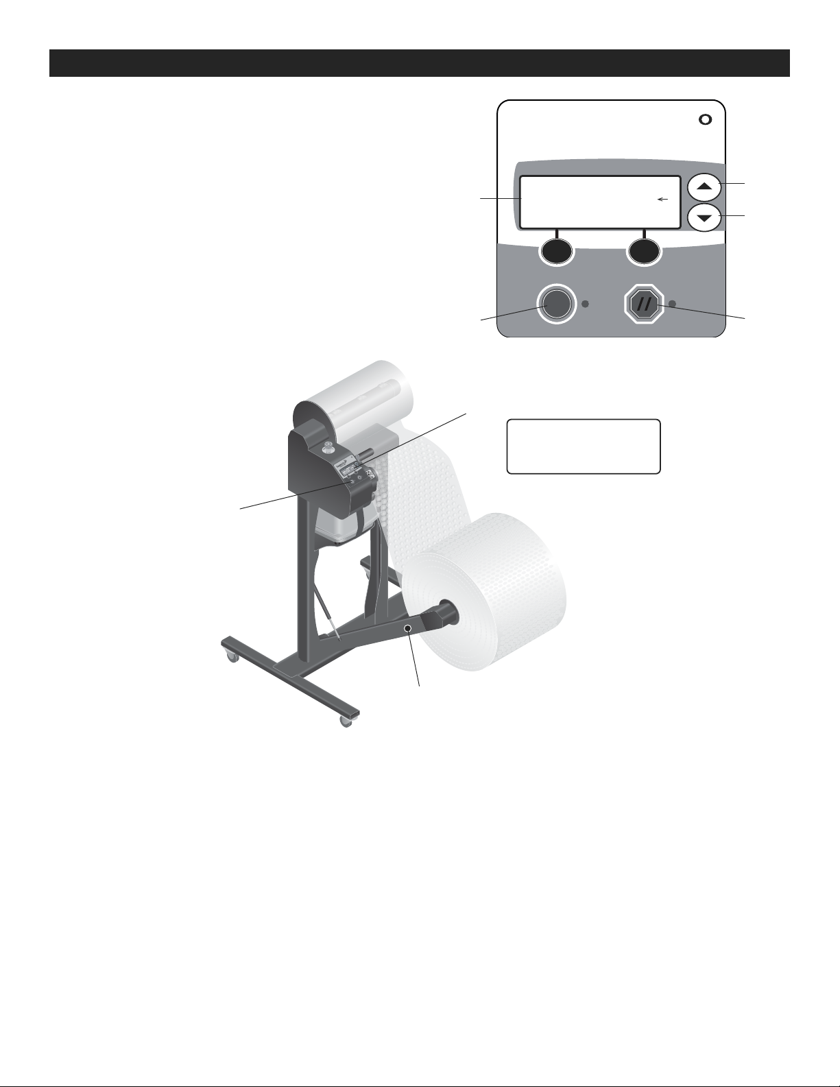
NO POWER TO THE SYSTEM
PROBLEM CAUSES RECOMMENDATIONS
There is no power to the
system and the control
panel display is OFF.
System is off.
Main power cord is unplugged at
the outlet.
Facility power supply is interrupted.
Electrical component failure.
Turn the main power switch to the on
position.
Verify the main power cord is plugged
into a properly rated outlet – see Electrical
Power Requirements on page 2.
Verify facility power supply – see Electrical
Power Requirements on page 2.
Contact Uline Customer Service at 1-800-
295-5510.
DISPLAYED FAULT MESSAGES
DISPLAYED MESSAGE CAUSES RECOMMENDATIONS
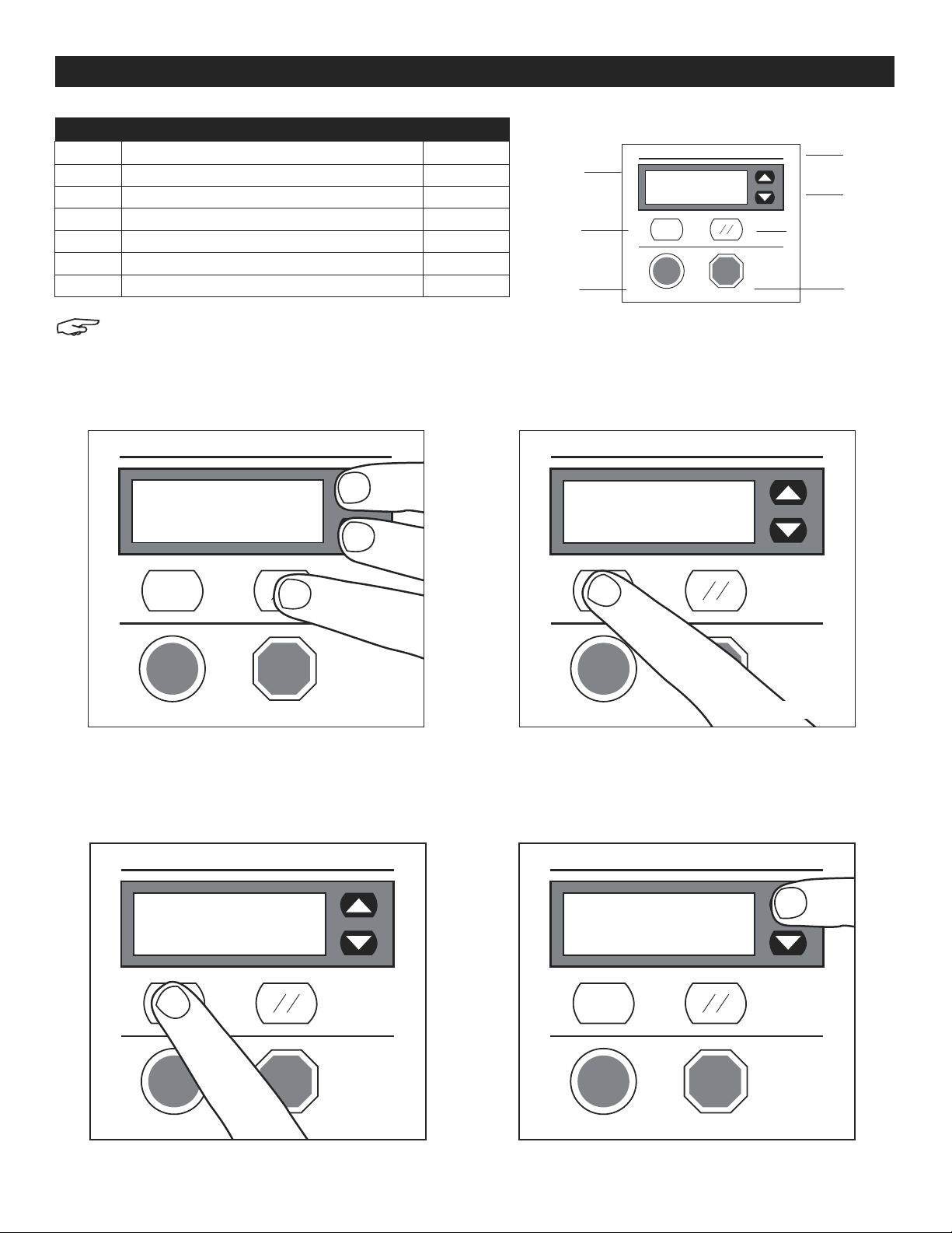
#01 E-Stop Pressed E-Stop switch pressed. Twist E-Stop to release.
#03 Clamp Open Edge seal clamp is open. Hinge the clamp handle up to close the
edge seal and press reset key.
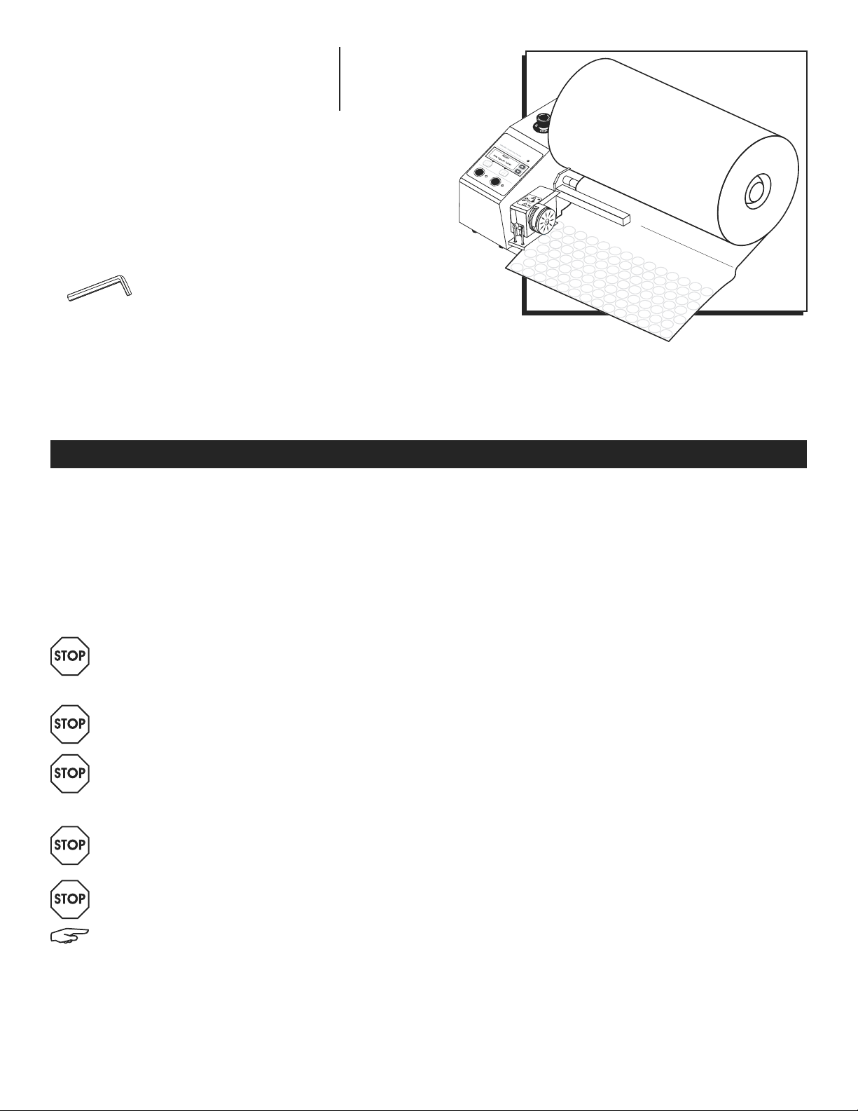
#17 Check Film Path Out of film.
Material roll is improperly loaded.
Load new roll.
Reload roll as required.
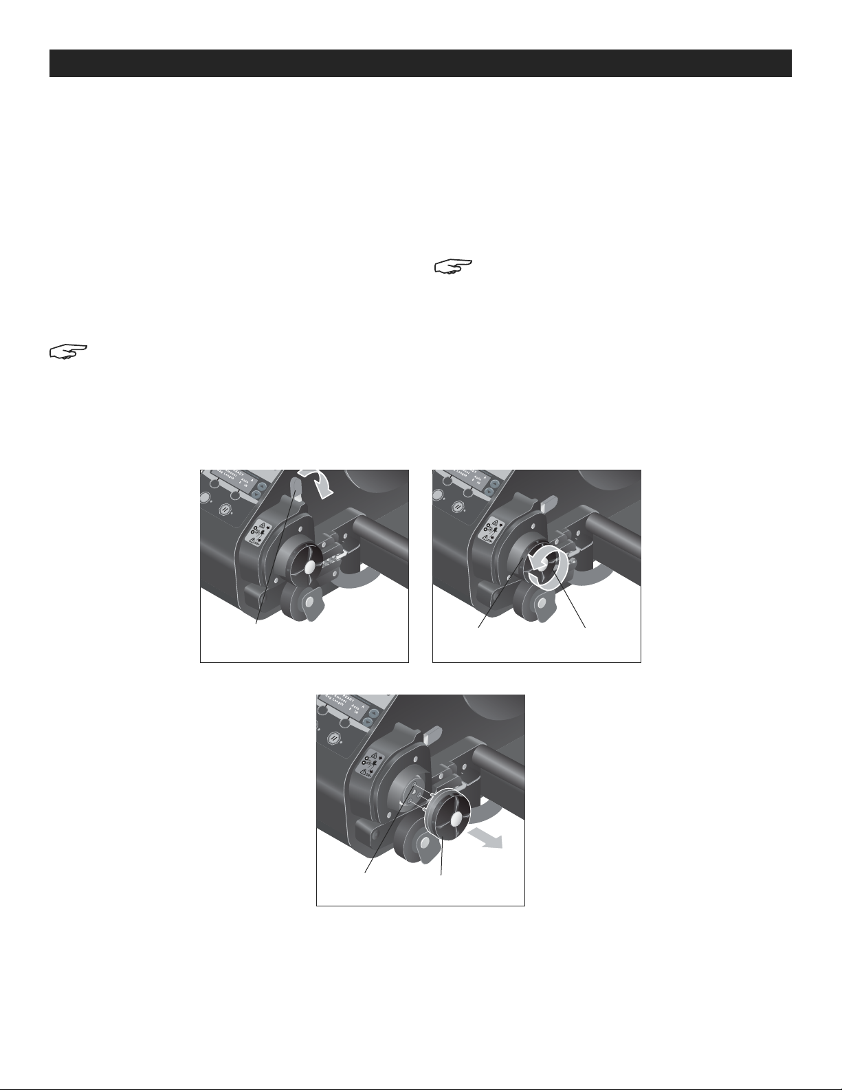
#07 Edge Seal Fault Edge seal wheel is missing or not
fully seated.
Edge seal failure.
Check condition of edge seal and verify
that it is fully seated.
Replace as required – see Replacing the
Edge Seal on page 7.
Contact Uline Customer Service.
PROBLEMS WITH MAKING INFLATED MATERIAL
PROBLEM CAUSES RECOMMENDATIONS
The material will not advance –
the control panel is on. Material roll is empty.
Material roll is improperly loaded.
Electrical or mechanical failure.
Load a new roll as required – See Loading
Material Roll on page 4.
Reload roll as required – See Loading
Material Roll on page 4.
Contact Uline Customer Service.
The material advances and
edge seals are present, but
the material does not fill
with air.
Material roll improperly loaded.
The material layers are not properly
wrapped around the inflation nozzle.
Faulty material.
Electrical or mechanical failure.
Verify that the open end of the material is
facing in towards the inflation nozzle.
Load new material – See Loading Material
Roll on page 4.
Return material roll – contact Uline
Customer Service.
Contact Uline Customer Service.
TROUBLESHOOTING

PAGE 9 OF 30 0318 IH-7259
PROBLEMS WITH MAKING INFLATED MATERIAL CONTINUED
PROBLEM CAUSES RECOMMENDATIONS
The material advances and
fills with air, but the material
does not seal properly.
Material roll improperly loaded.
Faulty edge seal.
Faulty material.
Seal power out of adjustment.
Electrical or mechanical failure.
Reload material roll – see Loading the
Material Load on page 4.
Check condition of edge seal on the material.
Check condition of edge seal and verify that
it is fully seated.
Replace as required – see Replacing the
Edge Seal.
Load new material – see Loading the Material
Roll on page 4.
Return material roll – contact Uline Customer
Service.
Remove, re-install and calibrate the edge
seal – see Replacing the Edge Seal on page 7.
Contact Uline Customer Service.
The inflated material leaks air. Material roll improperly loaded.
Faulty edge seal.
The operator is pulling the inflated
material directly out of the system
before the inflated material can cool.
Faulty material.
Seal power out of adjustment.
Electrical or mechanical failure.
Reload material – see Loading the Material
Roll on page 4.
Check condition of edge seal on the material.
Check condition of edge seal and verify that
it is fully seated.
Replace as required – see Replacing the
Edge Seal on page 7.
Do not attempt to pull inflated material from
machine.
Load new material – see Loading the Material
Roll on page 4.
Return material roll – contact Uline Customer
Service.
Remove, re-install and calibrate the edge
seal – see Replacing the Edge Seal on page 7.
Contact Uline Customer Service.
TROUBLESHOOTING CONTINUED

PAGE 10 OF 30 0318 IH-7259
PROBLEM CAUSES RECOMMENDATIONS
The inflated material has an
inconsistent air-fill amount. Material roll improperly loaded.
Faulty material.
Ambient temperature needs to be
reset.
Electrical or mechanical failure.
Material has been affected by
storage conditions.
Reload material roll – see Loading Material
Roll on page 4.
Load new material roll – see Loading Material
Roll on page 4.
Return material roll – contact Uline Customer
Service.
Unscrew top edge seal assembly and
reattach to recalibrate the temperature.
Contact Uline Customer Service.
Refer to storage conditions under Safety.
PROBLEMS WITH THE ROLL WINDING
PROBLEM CAUSES RECOMMENDATIONS
The roll winder will not wind
inflated material. The winder is stopped.
The winder is not plugged in.
Obstruction blocking the winder or
the roll.
Electrical or mechanical failure.
Press the winder start button – see
Producing Air-Filled Material in Roll Winder
Mode on page 6.
Verify that the roll winder is plugged in to
the bottom of the machine.
Verify the roll can wind free of obstruction.
Contact Uline Customer Service.
The roll is a different
diameter than expected. The diameter setting is set
incorrectly.
Material roll is empty.
Electrical or mechanical failure.
Verify diameter setting – see Producing
Air-Filled Material in Roll Winder Mode on
page 6.
Load a new roll as required – see Loading
Material Roll on page 4.
Contact Uline Customer Service.
TROUBLESHOOTING CONTINUED
πCHICAGO • ATLANTA • DALLAS • LOS ANGELES • MINNEAPOLIS • NYC/PHILA • SEATTLE • MEXICO • CANADA
1-800-295-5510
uline.com
If the problem persists or the troubleshooting section does not resolve or
describe your problem, contact Uline Customer Service at 1-800-295-5510.

PAGE 11 OF 30 0318 IH-7259
πH-7259 800-295-5510
uline.mx
MÁQUINA NEWAIR
INSTANT BUBBLE FLEX™
SEGURIDAD
ANTES DE OPERAR ESTA MÁQUINA:
1. Lea y comprenda cuidadosamente esta guía.
2. Lea y comprenda todas las etiquetas de
instrucciones adjuntas a la máquina.
3. Asegúrese de que la máquina esté conectada a
una toma de corriente debidamente conectada a
tierra.
¡ADVERTENCIA! Si no se conecta a tierra
correctamente, podría crear un riesgo de
descarga eléctrica.
¡ADVERTENCIA! No retire las guardas o las
cubiertas de acceso.
¡ADVERTENCIA! Riesgo de atrapamiento.
Mantenga los dedos, cabello suelto, ropa y
joyas lejos del borde del rodillo de la selladora
cuando el material se esté alimentando,
inflando y sellando.
¡ADVERTENCIA! Superficie Caliente. El borde del
rodillo de la selladora se calentará durante el
uso.
¡ADVERTENCIA! No utilice el material de
burbuja como equipo para flotar, juguete o
almohada.
NOTA: El usuario debe configurar y seleccionar
el tipo de película antes de su uso por primera
vez. Vea Configuraciones de los Códigos de la
Película en la página 15.
4. Inspecciónelo a intervalos regulares para asegurar
que:
• Los cables de los componentes no estén rotos,
dañados o pelados.
• Todos los controles e indicadores funcionen
adecuadamente.
5. Emisión de Ruido en el Aire:
• Esta máquina no excede de los 80 decibelios
durante una operación normal. Asegúrese de que
cumpla con los requerimientos locales de salud y
seguridad.
6. Condiciones Ambientales:
• Temperatura de Almacenamiento:
Máquina y rollos de material – 0˚-43˚C (32˚-110˚F).
• Temperatura de Operación:
Máquina y rollos de material – 16˚-43˚C (60˚-110˚F).
HERRAMIENTA NECESARIA
Llave Allen de 5/32”

PAGE 12 OF 30 0318 IH-7259
5
8
6
3
7
4
2
1
RESUMEN
COMPONENTES DEL SISTEMA
DESCRIPCIÓN DEL SISTEMA
La Máquina Instant Bubble Roll H-7259 crea material
de acojinado lleno de aire en el momento desde un
material de rollo preformado compacto/desinflado.
La cadena de material inflado está perforada en
secciones y puede ser separada fácilmente por el
operador según sea necesario.
Hay tres modos de operación:
MODO MANUAL
• Presione la tecla start para comenzar a producir el
material y la tecla stop para terminar la producción.
MODO POR LOTE
• Despache una longitud programada de material.
MODO BOBINADOR
• Requiere un bobinador de rollos opcional (H-7283) y
soporte (H-7284)
• Despache un rollo de material inflado.
REQUERIMIENTOS DE ENERGÍA ELÉCTRICA
¡ADVERTENCIA! El uso de un cable de
extensión incrementará los niveles de estática,
resultando en problemas operativos.
Sistema de Acojinado Inflable: 115 VC A
Tipo de Enchufe: NEMA 5-15R
Voltaje de C/A: 100-120 VCA 50/60 Hz
Fase: Puesta a Tierra de Una Sola Fase
ACTUAL: Servicio 15A de 4.0A
NOTA: El uso de materiales no compatibles
causará problemas de producción, puede
dañar el equipo y reducirá la calidad de la
protección del embalaje.
1. Interruptor ON/OFF
El interruptor controla la energía al sistema y está
localizado en la parte posterior de la máquina.
2. Interruptor de Freno de Emergencia (E-Stop)
El interruptor detiene toda la alimentación, inflado y
funciones de sellado.
3. Cable Principal
Conéctelo a un enchufe con clasificación
adecuada. Vea los Requerimientos de Energía
Eléctrica arriba.
4. Panel de Control
Este panel con pantalla LCD y teclas se usa para
operar, programar y diagnosticar el sistema. Vea
Operación en la página 5.
5. Mandril para el Material
Este montaje proporciona una posición para
desenrollar el material.
6. Ensamble del Sello en el Borde
Esta rueda como componente reemplazable crea
un sello en el borde, sellando el aire en el material.
Vea Reemplazo del Sello en el Borde en la página 17.
7. Bomba de Aire
Proporciona aire para llenar el material de burbujas.
8. Kit de Charola
Permite a la máquina descansar sobre una cubierta
de mesa.

PAGE 13 OF 30 0318 IH-7259
Diagrama 1 Diagrama 2
Diagrama 3
Diagrama 6
Diagrama 4
Diagrama 7
Diagrama 5
Diagrama 8
CONFIGURACIÓN DEL SISTEMA
1. Desempaque la máquina y el kit de charola.
2. Use una llave allen para atornillar los cuatro tornillos
de cabeza hueca en las cuatro patas de caucho.
(Vea Diagrama 1)
3. Acople los tornillos de goma a los cuatro orificios en
la parte inferior de la máquina. (Vea Diagrama 2)
4. Alinee cuatro tornillos de goma a sus orificios
correspondientes en el kit de charola. Asegure por
debajo del kit de charola con cuatro tuercas de
mariposa. (Vea Diagrama 3)
5. Pase la correa de gancho y felpa a través de las
ranuras en la bandeja de metal. (Vea Diagrama 4)
Coloque la bomba de aire en la parte posterior de la
charola, detrás de la máquina alineando las patas
de caucho en la bomba con los orificios en el kit de
la bandeja.
6. Viendo la parte frontal de la máquina, pase el
cable de alimentación de la bomba de aire por el
orificio circular derecho del kit de charola.
7. Asegure ambos extremos de la tira de gancho y
felpa para asegurar la bomba de aire al kit de
charola. (Vea Diagrama 5)
8. Conecte la manguera de aire de caucho tanto a
la válvula de la bomba de aire como a la válvula
debajo del tubo de llenado. Asegúrela con cinchos
para mantenerla en su lugar. (Vea Diagramas 6 y 7)
9. Incline la máquina e inserte el cable de la bomba
de aire dentro del enchufe. Gire para asegurar.
(Vea Diagrama 8)
10. Verifique que el enchufe de energía eléctrica
requerido esté instalado en la ubicación de la
máquina deseada.
11. Cargue el rollo de material.

PAGE 14 OF 30 0318 IH-7259
Diagrama 9 Diagrama 10 Diagrama 11
CARGA DEL ROLLO DE MATERIAL
NOTA: El usuario debe configurar y seleccionar
el tipo de película antes de su uso por primera
vez. Vea Configuraciones de los Códigos de la
Película en la página 15.
1. Cargue el rollo de material en el mandril para
material. (Vea Diagrama 9)
• Sostenga el nuevo rollo de material para que el
extremo abierto vea hacia el panel de control.
• Deslice el rollo completamente hasta el mandril
para que el extremo del centro haga contacto con
el collar.
2. Alimente el material al sistema (Vea Diagrama 10)
• Baje la manija de sujeción para abrir el ensamble
del sello del borde.
• Pase el material debajo del rodillo direccional
negro.
• Extienda el extremo abierto del material y envuelva
alrededor de la boquilla de inflado (tubo de metal
doblado) y la "solapa" del material.
• Páselo entre las dos ruedas en el ensamble del sello
del borde.
3. Cierre la manija y haga algunos metros de material
inflado de acojinado. (Vea Diagrama 11)
• Mientras mantiene la tensión en el material, eleve
la manija de sujeción para cerrar el ensamble del
sello del borde.
NOTA: Si el material no infla y/o sella después
de 20 cm, vuelva a alimentar el material.
Vea el paso dos.
CONTINUACIÓN DE LA CONFIGURACIÓN DEL SISTEMA
MENÚ DEL OPERADOR
Para ingresar al menú del operador, presione y
sostenga las flechas hacia arriba/hacia abajo ( , )
por cinco segundos.
Selección del Tipo de Película disponible para el
Operador
• ON permite al operador seleccionar los tipos de
películas.
• OFF no permite al operador seleccionar los tipos de
películas.
Ajuste del Tamaño del Rollo
• Ajuste el diámetro del rollo cuando utilice el brazo
bobinador de rollos (H-7283).
• 20-40" de diámetro
• Incrementos de 2".
Ajuste del Tamaño de Lote Disponible para el
Operador
• ON permite al operador ajustar los tamaños de lotes.
• OFF no permite al operador ajustar los tamaños de
lotes.
Mandril
"Solapa" del
Material
Boquilla
para
Inflar
Manija
(Abierta)
Ensamble del
Sello del Borde
Botón de Inicio
Manija
(Cerrada)

PAGE 15 OF 30 0318 IH-7259
INSTALL SET-UP
[Film 1 A124PT ]
Winder Dia 37"
SELECT BACK
Diagrama 14
FILM TYPE 4S
>Film Type A08C*
^
SELECT BACK
Diagrama 15
Diagrama 12
MENU
[Install Set-Up ]
Diagnostics
SELECT BACK
3. Utilice las flechas para mover el cursor "Film Type"
(Tipo de Película). Presione el botón "SELECT" en el
lado izquierdo para seleccionar "Film Type".
(Vea Diagrama 14)
4. Use las flechas y el botón de Seleccionar para
poner cada dígito del código de la película que
corresponda con el número de modelo. Después de
que el último dígito ha sido establecido, presione el
botón de Seleccionar para guardar el código de
película. (Vea Diagrama 15)
CONFIGURACIONES DE LOS CÓDIGOS DE LA PELÍCULA
CAMBIO DE LA CONFIGURACIÓN
DE LOS CÓDIGOS DE LA PELÍCULA
1. Presione las flechas hacia arriba o hacia abajo
y el botón de reconfigurar al mismo tiempo para
acceder al menú. (Vea Diagrama 12)
2. Utilice las flechas para mover el cursor de la
pantalla para "Engineering" (Ingeniería). Presione
el botón de seleccionar a la izquierda para elegir
"Engineering". (Vea Diagrama 13)
CONFIGURACIONES DEL CÓDIGO DE PELÍCULA
ARTÍCULO
NO. DIMENSIONES CÓDIGO DE
PELÍCULA
S-19738 Mediana Premium (1/2" inflada) 12" x 2,050' Perf. 12" A1S7LJ
S-19739 Mediana Premium (1/2" inflada) 24" x 2,050' Perf. 12" A1T7HT
S-19740 Grande Premium (3/4" inflada) 12" x 1,250' Perf. 12" A124PT
S-19741 Grande Premium (3/4" inflada) 24" x 1,250' Perf. 12" A124PT
S-19742 Extragrande Premium (1" inflada) 12" x 1,167' Perf. 12" A144RT
S-19743 Extragrande Premium (1" inflada) 24" x 1,167' Perf. 12" A1T4RT
NOTA: La configuración de película predeterminada de
fábrica es S-19740.
Flecha
hacia Arriba
Flecha
hacia Abajo
Pantalla
Seleccionar Reconfigurar
Botón para
Iniciar
Botón para
Detener
Diagrama 13

PAGE 16 OF 30 0318 IH-7259
READ Y
#1 A 167P T
Batch Size 19
OPERACIÓN
PRODUCCIÓN DE MATERIAL
DE RELLENO EN MODO POR LOTE
1. Presione las flechas hacia arriba o abajo para
ingresar al menú del operador.
• Seleccione "Batch Mode" (Modo por Lote).
2. Ajuste la longitud del lote.
• Usando las flechas hacia arriba y abajo, establezca
la longitud del lote en pies.
3. Presione el botón de Iniciar.
• Presione el botón de iniciar para comenzar el lote.
• Presione el botón de detener para pausar el lote.
Pantalla
Flecha
hacia Arriba
Flecha
hacia Abajo
Botón para
Iniciar
Botón para
Detener
OPERATOR MENU
Roll Size 37"˿
D37
SAVE CANCEL
Menú del
Operador
Botón de
Bobinado del Rollo
Botón para Iniciar
PRODUCCIÓN DE MATERIAL DE RELLENO
EN MODO DE BOBINADO
1. Presione el botón de liberación de la bobinadora
para bajar la bobinadora.
2. Establezca el diámetro del rollo.
• Presione y sostenga las flechas hacia arriba y hacia
abajo por cinco segundos para ingresar al menú
del operador.
• Desplácese al menú 2 "Roll Size" (Tamaño del Rollo).
• Usando las flechas hacia arriba y abajo, configure
el diámetro de 20-40" en incrementos de 2".
• Presione SELECT.
• Presione reconfigurar (//) para regresar a la ventana
de READY.
3. Cree 3 pies de material de relleno.
• Usando el botón de iniciar, cree 3 pies de material
de relleno.
• Usando el botón de Detener, detenga el sistema.
4. Deslice el borde del extremo delantero del material
de relleno en la ranura de la bobinadora.
5. Inicie la bobinadora.
• Mueva el botón de inicio de la bobinadora para
iniciar o detener la bobinadora.
6. Retire el rollo terminado de material de relleno.
• La bobinadora se detendrá automáticamente una
vez que el rollo alcance el diámetro programado.
• Corte a lo largo de la perforación y deslice el rollo
fuera de la bobinadora.

PAGE 17 OF 30 0318 IH-7259
Diagrama 16 Diagrama 17
Diagrama 18
MANTENIMIENTO PREVENTIVO
Mensualmente:
• Elimine todo el polvo y la suciedad de la máquina.
• Verifique cualquier desgaste inusual en los
componentes.
• Verifique que no haya desgaste o acumulación
inusual en el costado del ensamble del sello.
REEMPLAZO DEL SELLO DEL BORDE
Materiales necesarios:
• H-7287 Sellador de Bordes
NOTA: El sistema debe estar encendido para
el siguiente procedimiento. Asegure que los
componentes estén fríos antes de proceder.
1. Descienda la manija de sujeción para abrir el
ensamble del sello del borde.
2. Desenrosque el borde del sello girándolo en sentido
contrario a las manecillas del reloj.
(Vea Diagramas 17 y 18)
3. Tire de la rueda de sello del borde del engranaje
de plástico negro. (Vea Diagrama 18)
4. Instalación del nuevo sello del borde:
• Alinee los tres pasadores de conexión en la rueda
nueva con los tres orificios del receptáculo en el
asiento.
NOTA: El patrón de los orificios y pasadores
están en un patrón enchavetado.
• Con la mano, pase el sello del borde en el sentido
de las manecillas del reloj hasta que quede
apretado.
• No cargue la película. Eleve la manija para abrir el
ensamble del sello del borde.
5. Presione el botón de reconfigurar (//), luego el botón
de iniciar para calibrar el nuevo sello de borde.
Cargue la película.
MANTENIMIENTO Y REPARACIÓN
3 Orificios del
Receptáculo Llanta del Sello
del Borde
Manija
(Se Muestra Abierta) Llanta del
Sello del Borde
Engranaje
de Plástico
Negro

PAGE 18 OF 30 0318 IH-7259
NO HAY ENERGÍA EN EL SISTEMA
PROBLEMA CAUSAS RECOMENDACIONES
No pasa electricidad al
sistema y el panel de
control está apagado.
El sistema está apagado.
El cable principal de corriente
está desconectado.
No hay electricidad en el
edificio.
Falla del componente eléctrico.
Gire el interruptor de alimentación principal a
la posición de encendido.
Verifique que el cable de alimentación
principal esté enchufado en un tomacorriente
con la clasificación adecuada. Consulte los
Requisitos de energía eléctrica en la página 12.
Verifique la fuente de electricidad en el
edificio. Requisitos de energía eléctrica en la
página 12.
Comuníquese con Servicio a Clientes al
800-295-5510.
MENSAJES DE ERROR EN PANTALLA
MENSAJE MOSTRADO CAUSAS RECOMENDACIONES
#01 E-Stop Pressed El interruptor E-Stop está
presionado. Gire E-Stop para liberar.
#03 Clamp Open La manija del sello del borde
está abierta. Gire la manija hacia arriba para cerrar el sello
del borde y presione la tecla de reconfigurar.
#17 Check Film Path Ya no hay película.
El rollo de material no está
cargado adecuadamente.
Cargue un nuevo rollo
Vuelva a cargar el rollo apropiadamente.
#07 Edge Seal Fault Falta la llanta del sello
del borde o no está
completamente asentada.
Falla del sello del borde.
Verifique el estado del sello del borde y
verifique que esté completamente asentado.
Reemplace adecuadamente. Vea Reemplazo
del Sello en el Borde en la página 17.
Contacte a Servicio a Clientes de Uline.
PROBLEMAS AL HACER EL MATERIAL DE RELLENO
PROBLEMA CAUSAS RECOMENDACIONES
El material no avanza.
El panel de control está
encendido.
El rollo de material está vacío.
El rollo de material no está
cargado adecuadamente.
Falla eléctrica o mecánica.
Cargue un nuevo rollo apropiadamente. Vea
Carga del Rollo del Material en página 14.
Cargue nuevamente un rollo apropiadamente.
Vea Carga del Rollo del Material en página 14.
Contacte a Servicio a Clientes de Uline.
El material avanza y
hay sellos de bordes,
pero el material no se
llena con aire.
El rollo de material no está
cargado adecuadamente.
Las capas del rollo de
material no están envueltas
adecuadamente alrededor
de la boquilla para inflar.
Material defectuoso.
Falla eléctrica o mecánica.
Verifique que el extremo abierto del material
esté orientado hacia la boquilla para inflar.
Cargue un nuevo material. Vea Carga del Rollo
del Material en página 14.
Devuelva el rollo de material. Contacte a
Servicio a Clientes de Uline.
Contacte a Servicio a Clientes de Uline.
SOLUCIÓN DE PROBLEMAS

PAGE 19 OF 30 0318 IH-7259
CONTINUACIÓN DE PROBLEMAS AL HACER EL MATERIAL DE RELLENO
PROBLEMA CAUSAS RECOMENDACIONES
El material avanza y se
llena de aire, pero no se
sella adecuadamente.
El rollo de material no está
cargado adecuadamente.
Sello de borde defectuoso.
Material defectuoso.
Electricidad del sello
desajustado.
Falla eléctrica o mecánica.
Recargar rollo de material: consulte Carga de
material en la página 14.
Verifique el estado del sello del borde en el
material.
Verifique el estado del sello del borde y verifique
que esté completamente asentado.
Reemplace adecuadamente. Vea Reemplazo
del Sello en el Borde.
Cargue un nuevo material. Vea Carga del Rollo
del Material en página 14.
Devuelva el rollo de material. Contacte a
Servicio a Clientes de Uline.
Retire, vuelva a instalar y calibre el sello del
borde. Vea Reemplazo del Sello del Borde en la
página 17.
Contacte a Servicio a Clientes de Uline.
El material inflado
pierde aire. El rollo de material no está
cargado adecuadamente.
Sello de borde defectuoso.
El operador está sacando el
material de relleno directamente
del sistema antes de que el
material se enfríe.
Material defectuoso.
Electricidad del sello
desajustado.
Falla eléctrica o mecánica.
Cargue un nuevo material. Vea Carga del Rollo
del Material en página 14.
Verifique el estado del sello del borde en el
material.
Verifique el estado del sello del borde y verifique
que esté completamente asentado.
Reemplace adecuadamente. Vea Reemplazo
del Sello en el Borde en la página 17.
No intente extraer material inflado de la
máquina.
Cargue un nuevo material. Vea Carga del Rollo
del Material en página 14.
Devuelva el rollo de material. Contacte a
Servicio a Clientes de Uline.
Retire, vuelva a instalar y calibre el sello del
borde. Vea Reemplazo del Sello del Borde en la
página 17.
Contacte a Servicio a Clientes de Uline.
El material de relleno
tiene una cantidad de
aire inconsistente.
El rollo de material no está
cargado adecuadamente.
Material defectuoso.
La temperatura ambiente debe
restablecerse.
Falla eléctrica o mecánica.
El material ha sido afectado
por las condiciones de
almacenamiento.
Recargue el rollo de material: consulte Carga
de material en la página 14.
Cargue un nuevo material. Vea Carga del Rollo
del Material en página 14.
Devuelva el rollo de material. Contacte a
Servicio a Clientes de Uline.
Desenrosque el conjunto del sello del borde
superior y vuelva a conectarlo para calibrar otra
vez la temperatura.
Contacte a Servicio a Clientes de Uline.
Consulte las condiciones de almacenamiento
en Seguridad.
CONTINUACIÓN DE SOLUCIÓN DE PROBLEMAS

PAGE 20 OF 30 0318 IH-7259
PROBLEMAS CON EL BOBINADO DEL ROLLO
PROBLEMA CAUSAS RECOMENDACIONES
La bobinadora no
enrolla el material
inflado.
La bobinadora está detenida.
La bobinadora no está
conectada.
Hay una obstrucción en el rollo
bloqueando la bobina.
Falla eléctrica o mecánica.
Presione el botón de encendido en la
bobinadora. Vea Producción de Material de
Relleno en Modo de Bobinado de Rollos en la
página 16.
Verifique que el bobinador de rollos se
encuentre conectada a la parte inferior de la
máquina.
Verifique que el rollo se pueda bobinar libre
de obstrucciones.
Contacte a Servicio a Clientes de Uline.
El rollo es de un
diámetro diferente al
esperado.
La configuración del
diámetro está configurada
incorrectamente.
El rollo de material está vacío.
Falla eléctrica o mecánica.
Verifique la configuración del diámetro. Vea
Producción de Material de Relleno en Modo
de Bobinado de Rollos en la página 16.
Cargue un nuevo rollo apropiadamente. Vea
Carga del Rollo del Material en página 14.
Contacte a Servicio a Clientes de Uline.
CONTINUACIÓN DE SOLUCIÓN DE PROBLEMAS
Si el problema persiste o la guía de solución de problemas no resuelve el problema,
comuníquese con Servicio a Clientes al 800-295-5510.
πCHICAGO • ATLANTA • DALLAS • LOS ANGELES • MINNEAPOLIS • NYC/PHILA • SEATTLE • MEXICO • CANADA
800-295-5510
uline.mx
This manual suits for next models
1
Table of contents
Languages:
Other U-Line Industrial Equipment manuals

U-Line
U-Line H-9975 User manual

U-Line
U-Line H-9700 User manual

U-Line
U-Line H-2086 User manual

U-Line
U-Line H-3736 User manual

U-Line
U-Line H-951 User manual

U-Line
U-Line H-2108 User manual

U-Line
U-Line H-3797 User manual

U-Line
U-Line H-9045 User manual

U-Line
U-Line H-6482 User manual

U-Line
U-Line H-623 User manual

U-Line
U-Line S-108 User manual

U-Line
U-Line S-9737 User manual

U-Line
U-Line H-2035 Manual

U-Line
U-Line H-8928 Instruction Manual

U-Line
U-Line H-4435 User manual

U-Line
U-Line H-7170 User manual

U-Line
U-Line MINI PAK'R H-1604 User manual

U-Line
U-Line H-2176 User manual

U-Line
U-Line H-259 User manual

U-Line
U-Line H-3736 User manual