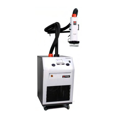
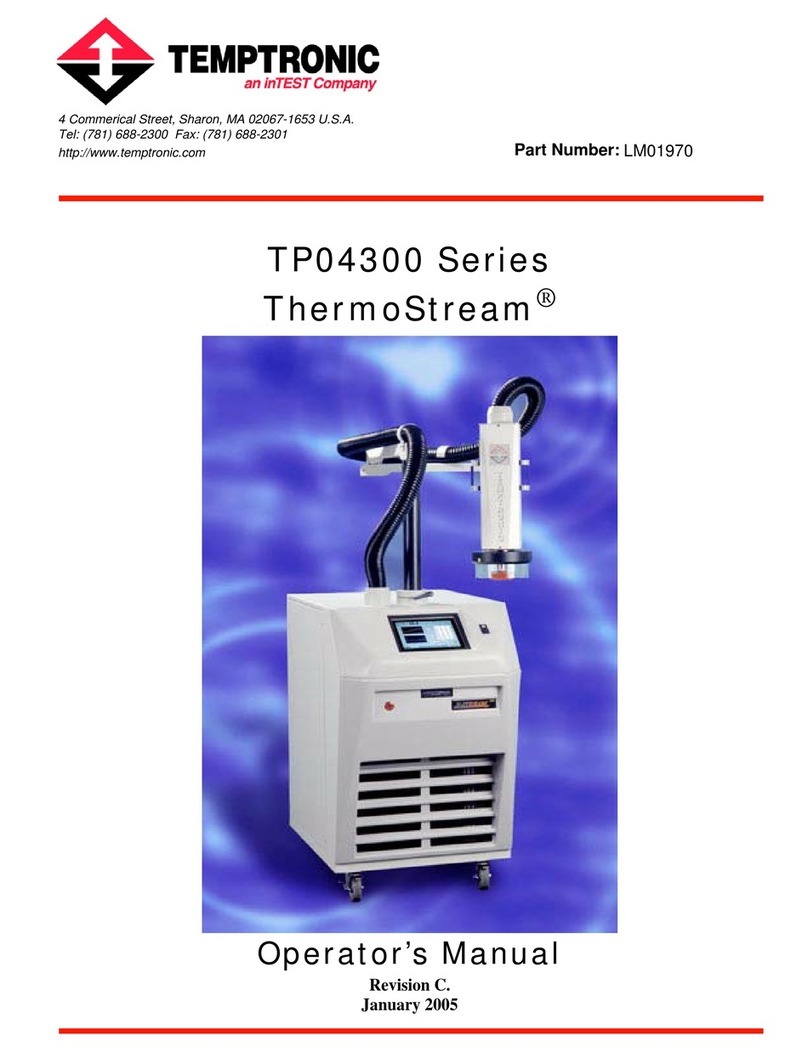
inTest THERMOSTREAM ATS-515 User guide

Part Number:
LQ7(677KHUPDO6ROXWLRQV
www.inTESTthermal.com
Tel: +1.781.688.2300
41 Hampden Road, Mansfield, MA 02048 U.S.A. LM02430
ATS-515, -525 & ATS-615, -625
THERMOSTREAM®
Interface & Applications
Manual
Revision A
January 2013


ATS-515, -525 & ATS-615 & -625 Interface & Applications Manual iii
. . . . .
. . . . . . . . . . . . . . . . . . . . . . . . . . . . . . . . . . .
Table of Contents
Preface
To Our Customers . . . . . . . . . . . . . . . . . . . . . . . . . . . . . . . . . . . . . . . . . . . . . . . . . . . . . . . . . . . . . . iii-vi
inTEST Thermal Solutions Support . . . . . . . . . . . . . . . . . . . . . . . . . . . . . . . . . . . . . . . . . . . . . . . . iii-vii
Before You Call. . . . . . . . . . . . . . . . . . . . . . . . . . . . . . . . . . . . . . . . . . . . . . . . . . . . . . . . . . . . . . . . iii-viii
Chapter 1. Safety
Chapter Overview . . . . . . . . . . . . . . . . . . . . . . . . . . . . . . . . . . . . . . . . . . . . . . . . . . . . . . . . . . . . . . 1-1
Warnings . . . . . . . . . . . . . . . . . . . . . . . . . . . . . . . . . . . . . . . . . . . . . . . . . . . . . . . . . . . . . . . . . . . . . 1-2
Cautions. . . . . . . . . . . . . . . . . . . . . . . . . . . . . . . . . . . . . . . . . . . . . . . . . . . . . . . . . . . . . . . . . . . . . . 1-5
Chapter 2. System Overview
Chapter Overview . . . . . . . . . . . . . . . . . . . . . . . . . . . . . . . . . . . . . . . . . . . . . . . . . . . . . . . . . . . . . . 2-1
Scope of Manual . . . . . . . . . . . . . . . . . . . . . . . . . . . . . . . . . . . . . . . . . . . . . . . . . . . . . . . . . . . . . . . 2-2
Related Documentation . . . . . . . . . . . . . . . . . . . . . . . . . . . . . . . . . . . . . . . . . . . . . . . . . . . . . . . . . . 2-3
User/Owner Documentation . . . . . . . . . . . . . . . . . . . . . . . . . . . . . . . . . . . . . . . . . . . . . . . . . . . . . . 2-4
System Description . . . . . . . . . . . . . . . . . . . . . . . . . . . . . . . . . . . . . . . . . . . . . . . . . . . . . . . . . . . . . 2-5
Environment . . . . . . . . . . . . . . . . . . . . . . . . . . . . . . . . . . . . . . . . . . . . . . . . . . . . . . . . . . . . . . . . . . 2-5
Receipt of Shipment . . . . . . . . . . . . . . . . . . . . . . . . . . . . . . . . . . . . . . . . . . . . . . . . . . . . . . . . . . . . 2-5
Unpacking Instructions . . . . . . . . . . . . . . . . . . . . . . . . . . . . . . . . . . . . . . . . . . . . . . . . . . . . . . . . . . 2-5
Repackaging System . . . . . . . . . . . . . . . . . . . . . . . . . . . . . . . . . . . . . . . . . . . . . . . . . . . . . . . . . . . . 2-6
Physical Requirements . . . . . . . . . . . . . . . . . . . . . . . . . . . . . . . . . . . . . . . . . . . . . . . . . . . . . . . . . . 2-6
Chapter 3. System Operation
Chapter Overview . . . . . . . . . . . . . . . . . . . . . . . . . . . . . . . . . . . . . . . . . . . . . . . . . . . . . . . . . . . . . . 3-1
Section A. Interconnections (Cables and Hoses)
ATS-515 & -525 Interconnect Diagram . . . . . . . . . . . . . . . . . . . . . . . . . . . . . . . . . . . . . . . . . . . . . 3-2
Section B. System Startup and Shutdown
. . . . . . . . . . . . . . . . . . . . . . . . . . . . . . . . . . . . . . . . . . . . . . . . . . . . . . . . . . . . . . . . . . . . . . . . . . . . . 3-4
Section C. Controls and Indicators
. . . . . . . . . . . . . . . . . . . . . . . . . . . . . . . . . . . . . . . . . . . . . . . . . . . . . . . . . . . . . . . . . . . . . . . . . . . . . 3-5
Section D. ATS-515 & -525 Screens Overview
. . . . . . . . . . . . . . . . . . . . . . . . . . . . . . . . . . . . . . . . . . . . . . . . . . . . . . . . . . . . . . . . . . . . . . . . . . . . . 3-8
Section E. ATS-515 & -525 Startup Screen
Air Purge and Compressor Delay Sequence . . . . . . . . . . . . . . . . . . . . . . . . . . . . . . . . . . . . . . . . . . 3-9
Section F. TOP MENU Screen
. . . . . . . . . . . . . . . . . . . . . . . . . . . . . . . . . . . . . . . . . . . . . . . . . . . . . . . . . . . . . . . . . . . . . . . . . . . . . 3-10
Section G. MANUAL OPERATION
Section Overview . . . . . . . . . . . . . . . . . . . . . . . . . . . . . . . . . . . . . . . . . . . . . . . . . . . . . . . . . . . . . . 3-12

TABLE OF CONTENTS
iv ATS-515, -525 & ATS-615 & -625 Interface & Applications Manual
MANUAL OPERATION Screen. . . . . . . . . . . . . . . . . . . . . . . . . . . . . . . . . . . . . . . . . . . . . . . . . . . 3-13
MANUAL TEST SETUP Screen. . . . . . . . . . . . . . . . . . . . . . . . . . . . . . . . . . . . . . . . . . . . . . . . . . . 3-14
MANUAL OPERATION “RAMP/CYCLE” Screen. . . . . . . . . . . . . . . . . . . . . . . . . . . . . . . . . . . . 3-16
Section H. PROGRAM OPERATION
Section Overview . . . . . . . . . . . . . . . . . . . . . . . . . . . . . . . . . . . . . . . . . . . . . . . . . . . . . . . . . . . . . . . 3-17
PROGRAM OPERATION Screen. . . . . . . . . . . . . . . . . . . . . . . . . . . . . . . . . . . . . . . . . . . . . . . . . . 3-18
PROGRAM TEST SETUP Screen. . . . . . . . . . . . . . . . . . . . . . . . . . . . . . . . . . . . . . . . . . . . . . . . . . 3-19
PROGRAM OPERATION “RAMP/CYCLE” Screen. . . . . . . . . . . . . . . . . . . . . . . . . . . . . . . . . . . 3-21
Section I. SETUP OPTIONS
Section Overview . . . . . . . . . . . . . . . . . . . . . . . . . . . . . . . . . . . . . . . . . . . . . . . . . . . . . . . . . . . . . . . 3-23
SETUP OPTIONS Screen . . . . . . . . . . . . . . . . . . . . . . . . . . . . . . . . . . . . . . . . . . . . . . . . . . . . . . . . 3-24
COPY SETUPS Screen . . . . . . . . . . . . . . . . . . . . . . . . . . . . . . . . . . . . . . . . . . . . . . . . . . . . . . . . . . 3-26
CALIBRATION CHOICE Screen . . . . . . . . . . . . . . . . . . . . . . . . . . . . . . . . . . . . . . . . . . . . . . . . . . 3-27
DEFINE PARAMETERS Screen. . . . . . . . . . . . . . . . . . . . . . . . . . . . . . . . . . . . . . . . . . . . . . . . . . . 3-28
Section J. CONFIGURE SYSTEM
CONFIGURE SYSTEM Screen Detailed . . . . . . . . . . . . . . . . . . . . . . . . . . . . . . . . . . . . . . . . . . . . 3-30
Section K. DIAGNOSTICS
DIAGNOSTICS Screen Detailed. . . . . . . . . . . . . . . . . . . . . . . . . . . . . . . . . . . . . . . . . . . . . . . . . . . 3-32
Chapter 4. Remote Interfaces
Overview. . . . . . . . . . . . . . . . . . . . . . . . . . . . . . . . . . . . . . . . . . . . . . . . . . . . . . . . . . . . . . . . . . . . . . 4-1
Section A. Remote Interfaces, Overview and Assumptions
Remote Interfaces Overview . . . . . . . . . . . . . . . . . . . . . . . . . . . . . . . . . . . . . . . . . . . . . . . . . . . . . . 4-2
Section B. Syntax
Syntax Overview . . . . . . . . . . . . . . . . . . . . . . . . . . . . . . . . . . . . . . . . . . . . . . . . . . . . . . . . . . . . . . . 4-3
Section C. Command Processing
Command Processing Overview. . . . . . . . . . . . . . . . . . . . . . . . . . . . . . . . . . . . . . . . . . . . . . . . . . . . 4-4
Section D. Error Reporting
. . . . . . . . . . . . . . . . . . . . . . . . . . . . . . . . . . . . . . . . . . . . . . . . . . . . . . . . . . . . . . . . . . . . . . . . . . . . . 4-5
Section E. Maximizing Communications Throughput
. . . . . . . . . . . . . . . . . . . . . . . . . . . . . . . . . . . . . . . . . . . . . . . . . . . . . . . . . . . . . . . . . . . . . . . . . . . . . 4-6
Section F. IEEE-488.2 Interface
Set: Bus Address. . . . . . . . . . . . . . . . . . . . . . . . . . . . . . . . . . . . . . . . . . . . . . . . . . . . . . . . . . . . . . . . 4-7
Section G. Serial Interface
Serial Interface Connector . . . . . . . . . . . . . . . . . . . . . . . . . . . . . . . . . . . . . . . . . . . . . . . . . . . . . . . . 4-8
Serial Interface Parameters. . . . . . . . . . . . . . . . . . . . . . . . . . . . . . . . . . . . . . . . . . . . . . . . . . . . . . . . 4-8
Serial Cables: 25 Pin, 9 Pin . . . . . . . . . . . . . . . . . . . . . . . . . . . . . . . . . . . . . . . . . . . . . . . . . . . . . . . 4-9
Section H. Remote Command Set
Remote Commands Overview . . . . . . . . . . . . . . . . . . . . . . . . . . . . . . . . . . . . . . . . . . . . . . . . . . . . . 4-10
IEEE Mandatory Commands . . . . . . . . . . . . . . . . . . . . . . . . . . . . . . . . . . . . . . . . . . . . . . . . . . . . . . 4-11
RS-232C Serial Commands . . . . . . . . . . . . . . . . . . . . . . . . . . . . . . . . . . . . . . . . . . . . . . . . . . . . . . . 4-13
Device Specific Commands . . . . . . . . . . . . . . . . . . . . . . . . . . . . . . . . . . . . . . . . . . . . . . . . . . . . . . . 4-14
Section I. MCT Interface
MCT Interface . . . . . . . . . . . . . . . . . . . . . . . . . . . . . . . . . . . . . . . . . . . . . . . . . . . . . . . . . . . . . . . . . 4-19
MSDS Overview. . . . . . . . . . . . . . . . . . . . . . . . . . . . . . . . . . . . . . . . . . . . . . . . . . . . . . . . . . . . . . . . A-1

ATS-515, -525 & ATS-615 & -625 Interface & Applications Manual v
. . . . .
. . . . . . . . . . . . . . . . . . . . . . . . . . . . . . . . . . .
Preface
©Copyright 2013 by Temptronic Corporation
All Rights Reserved
The text of this publication, or any part thereof, may not be reproduced or transmitted in any
form or by any means, electronic or mechanical, including photocopying, recording, or
otherwise, without the prior written permission of Temptronic Corporation.
The software program contained within the THERMOSTREAM®System is protected by
copyright laws that pertain to computer software. Use of this software does not authorize de-
compiling, disassembling, or reverse engineering to gain access to the program code.
Temptronic Corporation does not authorize any copy, change, or other use of this software.
Notice
Patents have been granted and/or patent applications are pending or are in process of
preparation on all our developments.
The material in this manual is for informational purposes and is subject to change without
notice.
Temptronic Corporation assumes no responsibility for any errors which may appear in this
manual

PREFACE
To Our Customers
vi ATS-515, -525 & ATS-615 & -625 Interface & Applications Manual
To Our Customers
This Manual The purpose of this manual is to help obtain the greatest return on your investment. inTEST
Thermal Solutions suggests that operators, supervisors, and technicians responsible for
operating and maintaining this equipment become familiar with the contents of these manuals
prior to using the equipment.
This manual instructs how to setup, operate and perform routine maintenance for the ATS-515, -
525 & ATS-525 & -625 THERMOSTREAM®Systems.
Other Manuals
in the Set Following is the complete list of manuals which make up this information set.
Manual Name Part Number
ATS-515, -525 & ATS-525 & -625 Interface and Applications Manual LM04030
ATS-515, -525 & ATS-525 & -625 Service Manual LM04040

. . . . .
PREFACE
inTEST Thermal Solutions Support
ATS-515, -525 & ATS-615 & -625 Interface & Applications Manual vii
inTEST Thermal Solutions Support
Introduction inTEST Thermal Solutions is committed to assisting end users and technicians to maintain
operational systems which are highly reliable. inTEST Thermal Solutions offers the following
support services.
Customer Training Formal technical training courses are available. The training courses cover the theory of
operation and the maintenance procedures for the System. For further information, contact the
inTEST Thermal Solutions Service Department.
Repair Service Temptronic maintains a fully equipped repair center at the factory plant for warranty and non-
warranty repairs. For further information on module and circuit board repairs, our exchange
program, and the availability of spare parts, contact the inTEST Thermal Solutions Service
Department.
Before returning any module or circuit board for repair, contact the inTEST Thermal Solutions
Service Department to obtain a return authorization (RA) number.
Spare Parts Electrical and mechanical replaceable parts for the System can be obtained through your local
inTEST Thermal Solutions representative, or directly from the inTEST Thermal Solutions
Service Department. When ordering, be sure to specify the:
• Quantity
• Temptronic part number
• Description
• Reference designation (if any)
• Complete model number and serial number of your system
For your convenience, Spare Parts Kits are available for different levels of service activity.
Technical Support Contact the inTEST Thermal Solutions Service Department by one of the following means:
ATTENTION
1. Please note that the 1.800 toll free telephone number is dedicated to Service Department
calls only. It is not possible to dial this number and to transfer to other departments within
inTEST Thermal Solutions.
2. The main telephone number, 781.688.2300, should be used for non-service related calls.
inTEST Thermal Solutions Technical Support
1.800.558.5080 Toll Free Telephone (service calls only)
service@inTESTthermal.com e-Mail Address
781.688.2302 Service FAX line
781.688.2300 Main Telephone line

PREFACE
Before You Call
viii ATS-515, -525 & ATS-615 & -625 Interface & Applications Manual
Before You Call
Introduction You can help us support your machine in timely fashion by having on hand specific
information when calling in:
• Software Version
• System Model Number
System Model
Number A modular system design allows the customer to select options or features as desired for a
given installation or application.
The System Model Number Designation, printed on the nameplate, reflects the configuration
at time of shipment as described below:

ATS-515, -525 & ATS-615 & -625 Interface & Applications Manual 1-1
LQ7(677KHUPDO6ROXWLRQV
1
. . . . .
. . . . . . . . . . . . . . . . . . . . . . . . . . . . . . . . . . .
Safety
Chapter Overview
Introduction This chapter covers all the safety Warnings and Cautions for the ATS-515, -525 & ATS-615 & -
625 THERMOSTREAM®Systems.
In this Chapter This Chapter is divided into the following Sections:
Topic See Page
Warnings 2
Cautions 5

1SAFETY
Warnings
1-2 ATS-515, -525 & ATS-615 & -625 Interface & Applications Manual
Warnings
WARNING
WARNING: Refer to Accompanying Documentation
Electrical Hazard
WARNING: High Voltage, Electrical Shock Hazard
Hot Surface
WARNING: Hot Surface
Cold Surface
WARNING: Cold Surface
WARNING 1: The locations of potentially dangerous voltages and other hazards such as hot
surfaces or cold surfaces or compressed air/gases/vapors at high pressures are identified and
labeled on the equipment. Be careful to observe these warnings when installing, operating,
maintaining, or servicing the equipment. Observe all warnings given in this manual. Only use
the equipment for the intended usages specified by the manufacturer.
WARNING 2: The troubleshooting instructions contained in this manual can involve a
possible contact with electrical power at high voltages, compressed air at high pressures, and
refrigerants at high or vacuum pressures. These hazards can be injurious or dangerous to life.
Do not perform these instructions unless you qualify to do them.
WARNING 3: To avoid shock hazard, the equipment must be grounded with an adequate
earth ground per local electrical codes.
WARNING 4: When connecting thermocouple sensors to the Device Under Test (DUT),
electrically isolate the sensors to protect operators from contact with any hazardous voltages
which could be present at the DUT site.
WARNING 5: Parts inside the thermal head operate at extremely hot and cold temperatures
and are dangerous to touch. Do not perform any maintenance inside the thermal head until the
system is turned off. Wait until the head parts have reached a safe and stable temperature near
ambient.
WARNING 6: Keep your fingers out of the space between the thermal cap on the head and the
DUT site during the up/down motion of the System’s thermal head.
WARNING 7: Per SEMI S2-93A, energized electrical work (“Hot Work”) is specified by
Type as follows:

. . . . .
SAFETY
Warnings
ATS-515, -525 & ATS-615 & -625 Interface & Applications Manual 1-3
WARNING 8: Where equipment must be fully de-energized (electrically “cold”) to allow safe
entry into system, the following Lockout/Tagout procedure is required per OSHA 29 CFR
1910: a) For devices with a power cord which “unplugs” from a service receptacle, the end
user must supply and tag a Plug lockout shell which completely encloses the plug and prevents
accidental reconnection; b) for devices hardwired to the electrical supply, the end user must
install and tag a power disconnect switch with a lock out position, or install and tag a circuit
breaker with a lock out position, to prevent accidental reconnection.
WARNING 9: To de-energize the System for safe replacement of a module, turn off the ac
power (cease operations and power down), then turn off the System’s air pressure supply, then
bleed all air from System by turning on ac power just long enough to exhaust all air from
System. Now disconnect both the main power supply cord and disconnect the air supply line
from air supply port fitting on the rear frame module. The only stored energy remaining in the
System will then be that within some electrical capacitors. One large capacitor is near the
System’s air-chiller compressor. Other large capacitors are in the System’s electrical power
supplies.
WARNING 10: If service of the Air Chiller Module is required, only a licensed (and/or EPA
Certified) refrigeration service person, authorized by the Temptronic Corporation, is qualified
to perform any charging or handling of the refrigerants in the System.
WARNING 11: Under no circumstances (leak testing or any other purpose) is the Air Chiller
Module to be charged with any gas at a pressure above 150 psig (10.34 bar).
WARNING 12: To prevent high-pressure ejection of condensate (which may or may not
contain injurious substances) when draining moisture from the air filter elements, first turn off
the System's air pressure supply, second bleed all air from the System by turning on ac power
to the System just long enough to exhaust air in the System, third disconnect the supply line
from the air supply port fitting located on the rear panel.
WARNING 13: When cleaning condenser air inlet fins, use a soft brush and/or vacuum
cleaner, taking care not to bend inlet fins; as fins have sharp edges, to prevent getting cut, wear
protective gloves and/or do not touch inlet fins directly with fingers.
TYPE DESCRIPTION (per SEMI S2-93A) EXPOSURE
THRESHOLD
1 Fully de-energized (electrically “cold.”) n.a.
2 Live circuits, covered or insulated. Work performed
at remote location to preclude accidental shock. n.a.
3 Live circuits exposed.
Accidental contact is possible.
<= 30v RMS, 42.2v peak,
240 volt-amps, and 20
Joules
4 Live circuits exposed.
Accidental contact is possible.
> 30v RMS, 42.2v peak,
240 volt-amps, and 20
Joules
5 Energized. Measurements & adjustments require
physical entry, or equipment configuration does not
allow use of clamp-on probes.
n.a.

1SAFETY
Warnings
1-4 ATS-515, -525 & ATS-615 & -625 Interface & Applications Manual
WARNING 14: Only use the coolants (heat transfer fluids) and refrigerants specified by the
manufacturer: they are carefully engineered to be safe for operating personnel, to be friendly to
the environment, to operate efficiently, and to not harm the equipment. Do not substitute
unauthorized coolants and refrigerants, nor mix (add) in unauthorized coolants or refrigerants:
doing so can cause warranties to be voided. Wear protective safety eye glasses, gloves, and
apron when filling coolants and refrigerants. Temptronic assumes no liability for damages
caused by use of unauthorized coolants and refrigerants.

. . . . .
SAFETY
Cautions
ATS-515, -525 & ATS-615 & -625 Interface & Applications Manual 1-5
Cautions
CAUTION
CAUTION: Refer to Accompanying Documentation
Electrical Hazard
CAUTION: High Voltage, Electrical Shock Hazard
Hot Surface
CAUTION: Hot Surface
Cold Surface
CAUTION: Cold Surface
CAUTION 1: Observe the precautions given on the equipment and within this manual to
prevent damage to the equipment. Only use the equipment for the intended usages specified by
the manufacturer.
CAUTION 2: Unauthorized personnel should not remove from the equipment those panels
which are provided for protection and/or cooling and/or require a tool to remove.
CAUTION 3: Use proper handling and packaging procedures for static-sensitive circuit
boards. Assume that all circuit boards are the static-sensitive type.
CAUTION 4: Before connecting the equipment to its electrical source, check that the ~ (ac)
voltage and frequency to be supplied to the system are correct for those listed on the system’s
data plate (located on the rear panel of the equipment).
CAUTION 5: Disconnect the system’s power cord from its service supply before checking or
replacing any back-up batteries.
CAUTION 6: Be very careful to avoid damaging the two thermocouples which go from the
Head thermal cutout board into the main air stream through various connector/supports. These
thermocouples are very delicate. Do not cut, twist, or bend them as internal connections can be
broken.
CAUTION 7: When removing the flow control board, be extremely careful to avoid flexing
the board when disconnecting the inlet and outlet air hoses. Even a slight flexing of the board
can damage delicate components and/or wiring on the board.
CAUTION 8: When making the system air connection to the System, hold the AIR INPUT
fitting with a second wrench while tightening the barb fitting to prevent the AIR INPUT fitting
from rotating in the panel.

1SAFETY
Cautions
1-6 ATS-515, -525 & ATS-615 & -625 Interface & Applications Manual
CAUTION 9: Use suitable Clean Dry Air (CDA) compressed air supply for the System: a) to
prevent premature fouling of the filters/regulator assemblies provided with the System, b) to
prevent ice forming from within the cooling module and possibly reducing or obstructing
output air flow. Improper air supply quality can cause damage to System internal operating
components.
CAUTION 10: Properly use and maintain the provided filters/regulator assemblies. Doing so
prevents moisture and/or compressor oils from being introduced into System operating
components. If left unchecked, moisture and/or compressor oil can cause damages to the
System which are not covered under warranty.

ATS-515, -525 & ATS-615 & -625 Interface & Applications Manual 2-1
LQ7(677KHUPDO6ROXWLRQV
2
. . . . .
. . . . . . . . . . . . . . . . . . . . . . . . . . . . . . . . . . .
System Overview
Chapter Overview
Introduction This chapter provides an overview of the ATS-515, -525 & ATS-615 & -625 THERMOSTREAM®
Systems.
In this Chapter This Chapter is divided into the following Sections:
Topic See Page
System Description 5
Physical Requirements 6

2SYSTEM OVERVIEW
Scope of Manual
2-2 ATS-515, -525 & ATS-615 & -625 Interface & Applications Manual
Scope of Manual
This manual supports the ATS-515, -525 & ATS-615 & -625 THERMOSTREAM®Systems for:
• General and advanced assembly
• Interfacing, interconnecting
• Local and Remote operation parameters for Medium and Full Access
• Routine preventive maintenance.
The THERMOSTREAM®System is a programmable temperature control airstream system,
used to test and characterize electronic devices in various thermal environments.
The THERMOSTREAM®System is controlled by internal microprocessors, and permits either
local or remote hosted operation, either attended or unattended. The system can record time/
temperature test performance datalogs.
The THERMOSTREAM®System displays the air and DUT (Device-Under-Test) temperatures.
It also displays various operator input values, such as: hot, ambient, and cold temperature
setpoints, soak times and cycle data, and further displays system derived operations status data
and error message alerts.
Data is displayed in real-time alphanumeric format, to fully inform the operator or test setup
engineer.

. . . . .
SYSTEM OVERVIEW
Related Documentation
ATS-515, -525 & ATS-615 & -625 Interface & Applications Manual 2-3
Related Documentation
Introduction This manual (LM04070) is one of two used with the ATS-515, -525 & ATS-615 & -625
THERMOSTREAM®Systems. This section provides a description of the manuals and other
related documentation.
ATS-515, -525 & ATS-
615, -625
THERMOSTREAM®
Documentation
The following is a list of manuals and other pertinent documentation related to the ATS-515, -
525 & ATS-615 & -625 THERMOSTREAM®Systems:
Title Part Number Description
ATS-515, -525 & ATS-615
& -625
THERMOSTREAM®
Service Manual
LM04040 • General Safety
• System Description, Physical
Requirements/Dimensions
• Complete Parts Pictorial
• Complete Parts List
• System Troubleshooting Tables
• Repair Procedures for all major assemblies
• System Drawings/Schematics
ATS-515-M
THERMOSTREAM®
Datasheet
SL10720 • Datasheet and technical specifications
ATS-525-T
THERMOSTREAM®
Datasheet
SL10820 • Datasheet and technical specifications
ATS-615
THERMOSTREAM®
Datasheet
SL 10920 • Datasheet and technical specifications
ATS-625
THERMOSTREAM®
Datasheet
SL10930 • Datasheet and technical specifications
ATS
THERMOSTREAM®
Systems -500 Series
Brochure
SL10700 • Brochure for 60Hz only systems describing
overview of all models.
ATS
THERMOSTREAM®
Systems -600 Series
Brochure
SL10710 • Brochure for 50/60Hz systems describing
overview of all models.

2SYSTEM OVERVIEW
User/Owner Documentation
2-4 ATS-515, -525 & ATS-615 & -625 Interface & Applications Manual
User/Owner Documentation
Introduction The following section details the owner’s warranty and System Specifications for the
THERMOSTREAM®System.
Warranty A copy of Temptronic Corporation’s standard Warranty is available on the inTEST Thermal
Solutions website: http://intest-thermal.com/warrantytemptronic.
Specifications The System Specifications are as published on the data sheet(s) which is (are) included in the
front cover pocket of this manual, or inserted immediately at the end of this Manual.
Specifications typically include:
• Temperature range, Air flow, Vacuum
• Environmental, Service features
• Facilities requirements: Power, Dewpoint/humidity
• Air Standards: Supply Pressure, Oil Content, Filtration
•Dimensions

. . . . .
SYSTEM OVERVIEW
System Description
ATS-515, -525 & ATS-615 & -625 Interface & Applications Manual 2-5
System Description
The ATS-515, -525 & ATS-615 & -625 THERMOSTREAM®is a stand alone unit capable of -45C
to +225C operation. The THERMOSTREAM®can be controlled directly from the front panel
or via IEEE or RS-232 communication from a remote host. The THERMOSTREAM®uses a
two stage compressor system and a liquid circulator in a hermetically sealed closed loop
refrigeration system. High efficiency heat exchangers interface the separate refrigerant and
fluid coolant loops. The Chiller contains environmentally safe and approved refrigerants and
contains NO chlorofluorocarbons (CFCs) and NO Hydro-chlorofluorocarbons (HCFCs).
Environment
The ATS-515, -525 & ATS-615 & -625 THERMOSTREAM®meets the following environmental
requirements:
Receipt of Shipment
The THERMOSTREAM®System is shipped in one large packing carton, on a skid, and can be
transported to its location with a single fork-lift. All purchased items are included inside the
packing carton. When received, the carton should be examined for any signs of mishandling or
damage during shipment.
NOTE: If there are any obvious signs of damage to the packing carton, contact the carrier
immediately and do not proceed with the unpacking.
Unpacking Instructions
CAUTION
CAUTION 5: Some of the packing materials in the system’s shipment may be a source of
Electrostatic Discharge (ESD) potential. Do not unpack in the vicinity of ESD sensitive
components. Assume that all circuit boards are the ESD sensitive type. When unpacking the
Storage Temperature 0 to +50 °C
Operating Temperature: +15 °C to +28 °C
Humidity 0 to 90% non-condensing
Noise Level 65 dBA at 1 meter (typical)
Pollution Degree II
Installation Category II

2SYSTEM OVERVIEW
Repackaging System
2-6 ATS-515, -525 & ATS-615 & -625 Interface & Applications Manual
system, save all packaging material in the event the system has to be reshipped later.
Repackaging System
If the system is to be shipped to another location, repackage the system in the original shipping
carton, by reversing the order of unpacking.
NOTE: Prior approval is required before shipping the system to a inTEST Thermal Solutions
Sales/Service Office, or to the factory.
ATTENTION
IT IS RECOMMENDED THAT A TAG BE ATTACHED TO THE SYSTEM GIVING THE
SYSTEM OWNER'S NAME, ADDRESS, TELEPHONE NUMBER, SYSTEM MODEL
AND SERIAL NUMBERS, AND THE REASON FOR RETURN.
Physical Requirements
Introduction The ATS-515, -525 & ATS-615 & -625 THERMOSTREAM®is a free standing unit. A cover
encloses the THERMOSTREAM®and prevent personnel from coming into contact with
dangerous electrical terminals, air at high pressure, and refrigerants at vacuum pressures.
Dimensions,
Weights (ATS-515, -
525 & ATS-615 & -
625)
Benchtop Controller:
Refrigeration Module (Chiller):
Ventilation The THERMOSTREAM®intakes air through front panel grills and exhausts air through its rear
panel grill. Allow 8-inches clearance, front and rear, for ventilation
Height Width Depth
20.65cm
(8.13 inches)
26.7cm
(10.5 inches)
9.75cm
(3.84 inches)
Height Width Depth Weight
41.45cm
(16.32 inches)
51.3cm
(20.20 inches)
74.93cm
(29.5 inches)
74.5 kg
(157 lbs.)
This manual suits for next models
3
Table of contents
Other inTest Test Equipment manuals
Popular Test Equipment manuals by other brands

Transmille
Transmille 4610M Programming manual
DENTSPLY
DENTSPLY AUSTENAL ELECTROMATIC-4 Operation manual
Aeroflex
Aeroflex TCAS-201-2 Operation manual

Apera Instruments
Apera Instruments TDS20 instruction manual

Innovative Technology
Innovative Technology MyCheckr quick start guide
Anritsu
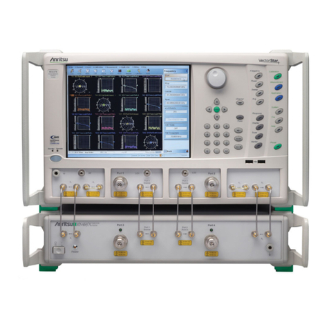
Anritsu MN469xC Series installation guide
