User’s
Manual
All Rights Reserved. Copyright ©
2008, Yokogawa Meters & Instruments Corporation,
2017, Yokogawa Test & Measurement Corporation
Printed in Japan
Store this manual in an easily
accessible place for quick reference.
Safety Precautions
This product is designed to be used by a person with specialized
knowledge. When operating the instrument, be sure to observe
the cautionary notes given below to ensure correct and safe use
of the instrument. If you use the instrument in any way other than
as instructed in this manual, the instrument’s protective measures
may be impaired. This manual is an essential part of the product;
keep it a safe place for future reference.
YOKOGAWA is by no means liable for any damage resulting from
use of the instrument in contradiction to these cautionary notes.
The following safety symbols are used on the instrument
and in this manual:
Danger! Handle with Care
This symbol indicates that the operator must refer
to an explanation in the instruction manual in order
to avoid the risk of injury or death of personnel or
damage to the instrument.
WARNING
Indicates a hazard that may result in the loss of life or serious
injury of the user unless the described instruction is abided by.
CAUTION
Indicates a hazard that may result in an injury to the user and/or
physical damage to the product or other equipment unless
the described instruction is abided by.
Model 30031A
Leakage Clamp-on Tester
IM 30031A-E
6th Edition:
February 2021 (YMI)
This symbol indicates that this instrument designed to be
applied around or removed from HAZARDOUS LIVE conductors
provided if the RATED circuit-to-earth voltage does not exceed
the value indicated in the measurement category
Double Insulation
This symbol indicates double insulation.
Alternating Current
This symbol indicates alternating current (AC).
Direct Current
This symbol indicates direct current (DC).
Earth TERMINAL
This symbol indicates ground.
■ Strictly observe the following cautionary notes in order to
avoid the risk of injury or death of personnel or damage to
the instrument due to hazards such as electrical shock.
WARNING
• This instrument is a current measuring device (sensor).
Do not use for any other purpose.
• Do not use the instrument if there is a problem with its physical
appearance. (Do not use the instrument if there is any damage
to the casing, battery cover, display and labels or when the
casing is removed.)
• The barrier is there to protect you from touching the conductor.
Be careful not to reach cross the barrier when using the
instrument.
• Disconnect the instrument from the measurable conductors
under test before opening the casing to replace the battery.
• Do not use the product when there are raindrops or droplets of
condensed water on its surface, or if your hands are wet.
• Safety protectors such as rubber-insulated gloves should be
worn to prevent electrical shock when using the instrument.
• Do not use this product in a place where an explosive gas or
vapor is present.
• Do not open the case except when replacing batteries.
Only Yokogawa service personnel are authorized to remove
the casing or disassemble or modify the instrument.
Do not attempt to repair the instrument yourself, as doing so is
extremely dangerous.
When the instrument needs an internal inspection or calibration,
contact Yokogawa or the dealer from whom you purchased the
instrument.
WARNING
The maximum allowed current is 62 Arms and the RATED circuit-
to-earth voltage is 300 Vrms or less.
Do not apply input exceeding this value.
Otherwise, it will not only damage the tester, but also pose a risk
of damage to the human body.
For safety standards, refer to the specications.
CAUTION
The use of this instrument is limited to residential, commercial,
and light-industrial environments.
This instrument may not be able to measure accurately if it is near
other equipment generating strong electromagnetic interference
or a strong magnetic eld caused by large current.
CAUTION
• The jaw section is a delicate, precision sensor.
Do not subject the jaw to unreasonably strong shock, vibration,
or force when using it.
• If dust gets into the tops of the jaws, remove it immediately.
Do not close the jaws when dust is trapped in its joints as
the sensor may break.
CAUTION
• Do not use the instrument near noise-emitting equipment or
where there may be sudden changes in temperature.
Otherwise, the instrument may produce an unstable readings or
errors.
• Do not wipe the instrument using an organic solvent such as
benzine or paint thinner.
Otherwise, the front panel may be damaged or discolored.
When cleaning the instrument, use a dry cloth.
• Do not leave the tester exposed to direct sunlight or in a hot and
humid location such as the inside of a car, for any prolonged
length of time.
• If the instrument will not be used for long periods, remove the
battery.
■ Measurement Category
WARNING
The 30031A is designed for measurement category III.
Do not use the 30031A for measurements in location that fall
under measurement category IV.
Measurement
category Description Remarks
O
(None, Other)
For measurements performed on
circuits not directly connected to
MAINS.
Circuits not connected to
a mains power source.
CAT II
For measurements performed on
circuits directly connected to the
low-voltage installation.
Appliances, portable
equipment, etc.
CAT III For measurements performed in
the building installation.
Distribution board,
circuit breaker, etc.
CAT IV
For measurements performed
at the source of the low-voltage
installation.
Overhead wire,
cable systems, etc.
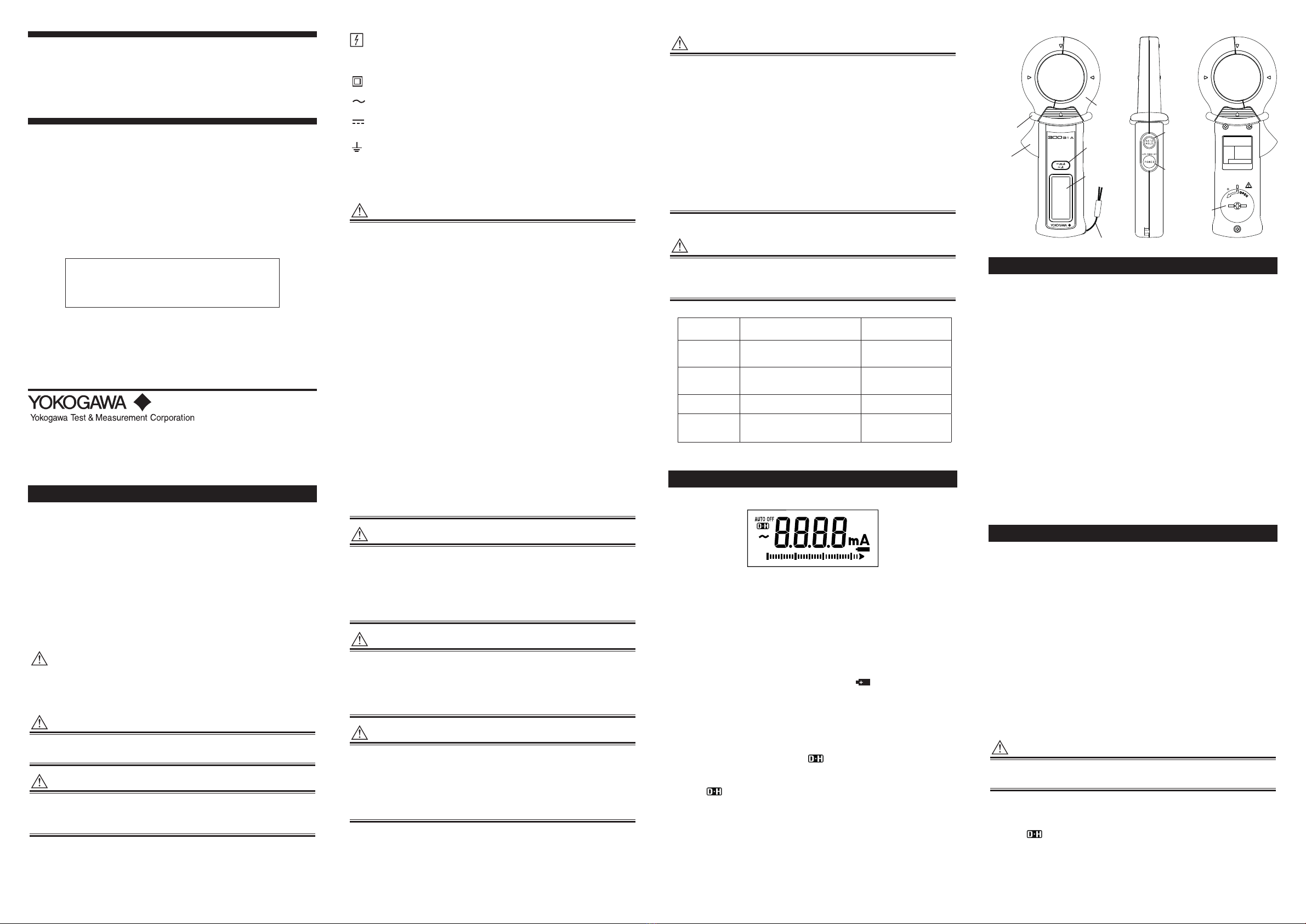
1. Components
1.1 Display (LCD)
1.2 Main unit (30031A)
1) Jaw Section
Is a precision sensor for detecting currents.
2) Open/Close Lever
Opens and closes the jaws.
3) Display
Shows the measured value (digital reading or bar graph),
unit, function and low-battery symbol ( ).
4) mA/A Selector Switch
Selects the unit of AC current (either “mA” or “A”) to be
measured.
5) Data Hold Switch
Retains the measured data.
If you press this switch, the symbol appears and the data
is retained.
If you press this switch once again, data holding is canceled
(the symbol disappears).
6) Power Switch
Turns on the power to the instrument.
7) Battery Housing (Battery cover)
Contains the battery.
8) Barrier
Prevents contact with the wires.
Thank you for purchasing our Leakage Clamp-on Tester.
Before using this product, thoroughly read this manual
to understand how to use it properly.
Contact information of Yokogawa oces worldwide is
provided on the following sheet.
PIM 113-01Z2: Inquiries List of worldwide contacts
close lever
1) Jaw
section
4) mA/A
selector
switch
3) Display
7) Battery
housing
(cover)
6) Power
switch
5) Data hold
switch
2. AUTO POWER OFF Function
2.1 When the AUTO POWER OFF Function is Used
• AUTO OFF appears.
• The instrument automatically turns o 10 minutes after
the last switch operation. A buzzer starts to beep 15 seconds
before the automatic power-o.
• Pressing any switch after the beep restarts the auto power-o
function.
2.2 When the AUTO POWER OFF Function is not Used
(Cancellation of the AUTO POWER OFF Function)
• Turn o the power.
• With the DATA HOLD switch held down, press the POWER
switch for more than 2 seconds to turn on the power.
This causes the buzzer to sound, canceling the AUTO POWER
OFF function (the AUTO OFF display goes o).
If the instrument is used with the AUTO POWER OFF function
cancelled, take care not to let the battery run down.
2.3 Recovering the AUTO POWER OFF Function
• Turn o the power.
• Turn on the power. This enables the AUTO POWER OFF
function to recover. (AUTO OFF appears.)
3. Measuring Instructions
3.1 Before measurement
a) Examine the casing, battery cover, display, and labels of
the instrument for abnormalities.
b) Make sure that the battery cover is rmly closed.
3.2 AC Current Measurement (unit: mA/A)
a) Press the POWER switch to turn on the power.
b) Squeeze the open/close lever to open the jaws.
Insert a wire from the measurable conductors under test
through the jaws, making sure the tops of the jaws are tightly
shut.
c) When the reading stabilizes, read the value.
If you have diculties in reading the value,
use the DATA HOLD function.
d) When measuring Load Current, press the mA/A switch to
change to A range.
e) When you have nished measurement,
press the POWER switch to turn o the tester.
CAUTION
The correct measured values are not displayed if the jaws
do not t precisely. Make sure that they are shut tightly.
3.3 Using the DATA HOLD switch
Pressing the DATA HOLD switch retains the measured data and
displays .
The mA/A selector switch cannot be used in this situation.
The only switches that can be used are the DATA HOLD switch
(to cancel data holding) and the POWER switch.


