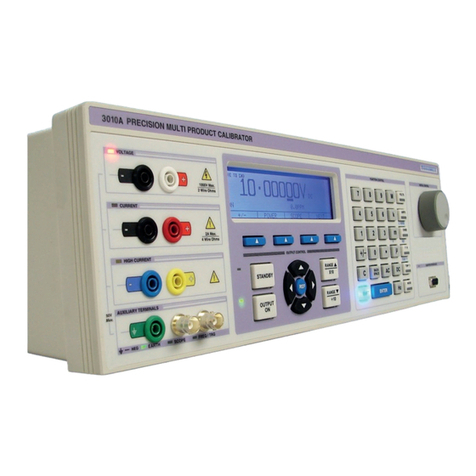
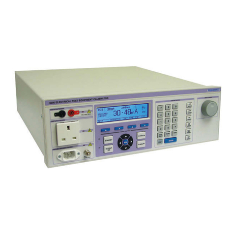
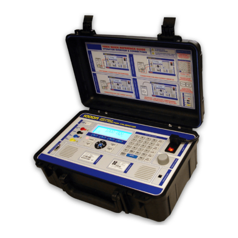
Transmille 4610M Owner's manual

Model 4610M
Precision Multi Product Calibrator
Programming Manual
Version 2.02 : August 2021
All product names are trademarks of their respective companies

Model 4610M Operation Manual
TRANSMILLE LTD. V2.02 - August 2021 Page 2
TABLE OF CONTENTS
1. Introduction................................................................................................................................. 5
1.1. Main Features...................................................................................................................................................5
1.2. Accuracy and Functionality ..............................................................................................................................5
1.3. True Multiproduct Calibration ...........................................................................................................................5
1.4. Retro Fit Options...............................................................................................................................................6
1.5. USB Interface ...................................................................................................................................................6
1.6. GPIB (IEEE488) Interface.................................................................................................................................6
1.7. Output Connections ..........................................................................................................................................6
2. Command Modes........................................................................................................................ 6
2.1. Transmille .........................................................................................................................................................6
2.2. 55xx ..................................................................................................................................................................6
2.3. Changing Command Mode - Front Panel .........................................................................................................7
2.4. Changing command Mode - Remote Interface.................................................................................................8
2.4.1. ‘Transmille’ command mode...............................................................................................................8
2.4.2. ‘55xx’ command mode........................................................................................................................8
2.5. Querying Command Mode - Remote Interface.................................................................................................8
3. Transmille Commands ............................................................................................................... 9
3.1. Response / Error Codes ...................................................................................................................................9
3.2. Programming Commands Overview...............................................................................................................10
3.3. Compound / Chained Commands...................................................................................................................10
3.4. Setting Output Status...................................................................................................................................... 11
3.5. Querying Output Status .................................................................................................................................. 11
3.6. Functions ........................................................................................................................................................12
3.6.1. DC Voltage .......................................................................................................................................12
3.6.2. AC Voltage........................................................................................................................................12
3.6.3. DC Current .......................................................................................................................................13
3.6.4. AC Current........................................................................................................................................14
3.6.5. Passive Resistance Output ..............................................................................................................16
3.6.6. Passive Capacitance output.............................................................................................................17
3.6.7. Simulated Resistance.......................................................................................................................18
3.6.8. Simulated Capacitance output..........................................................................................................19
3.6.9. PWM.................................................................................................................................................20
3.6.10. Simulated PRT .................................................................................................................................20
3.6.11. Thermocouple Output.......................................................................................................................21
3.6.12. Thermocouple Measurement............................................................................................................22
3.7. Calibration Commands ...................................................................................................................................23

Model 4610M Operation Manual
TRANSMILLE LTD. V2.02 - August 2021 Page 3
3.7.1. Enable / Disable Calibration Mode ...................................................................................................23
3.7.2.
Querying Calibration State (Locked / Unlocked) ..............................................................................23
3.7.3. Storing Calibration Changes.............................................................................................................23
3.7.4. Abort Calibration Changes ...............................................................................................................24
3.7.5. Perform a backup of calibration factors............................................................................................24
3.7.6. Restore to factory calibration............................................................................................................24
3.7.7. Restore range to default factors .......................................................................................................24
3.7.8. Performing an Adjustment ................................................................................................................25
3.7.9. Exporting Calibration to USB (Service Mode) ..................................................................................26
3.7.10. Querying Calibration Factor Value....................................................................................................26
3.8. Miscellaneous Commands..............................................................................................................................27
3.8.1. Earth Relay / Negative To Ground....................................................................................................27
3.8.2. Reset Calibrator To Startup ..............................................................................................................27
3.8.3. System ID.........................................................................................................................................27
3.8.4. Query Output....................................................................................................................................28
3.8.5. ONTIME?..........................................................................................................................................28
3.8.6. QuerySpecication ..........................................................................................................................28
3.8.7. Set Local Operation..........................................................................................................................28
3.8.8. Increment Output..............................................................................................................................29
3.8.9. Query Errors.....................................................................................................................................29
4. 55XX Command Mode.............................................................................................................. 30
4.1. Description.....................................................................................................................................................30
4.2. Commands......................................................................................................................................................30
4.2.1. EARTH .............................................................................................................................................30
4.2.2. FUNC?..............................................................................................................................................30
4.2.3. ONTIME?..........................................................................................................................................31
4.2.4. *RST.................................................................................................................................................31
4.2.5. OPER ...............................................................................................................................................31
4.2.6. RANGELCK......................................................................................................................................31
4.2.7. STBY ................................................................................................................................................32
4.2.8. OUT..................................................................................................................................................32

Model 4610M Operation Manual
TRANSMILLE LTD. V2.02 - August 2021 Page 4
LIST OF FIGURES
Figure 1 – Calibrator Home Screen....................................................................................................... 7
Figure 2 – Calibrator Main Menu........................................................................................................... 7
Figure 3 – Calibrator Home Screen....................................................................................................... 8

Model 4610M Operation Manual
TRANSMILLE LTD. V2.02 - August 2021 Page 5
1. INTRODUCTION
The 4610M calibrator offers the most advanced and up to date means of calibration of a wide variety
of electrical measuring instruments. The 4610M advanced multi product calibrator provides a fully
functional, precision programmable calibration source.
1.1. MAIN FEATURES
• AC/DC Volts to 1025 V
• AC/DC Current to 30 Amps
• AC/DC Current to 1500 Amps with EA002 50 turn clamp coil adapter (option)
• 2 and 4 wire passive resistance to 1 GΩ
• 2 wire, 2 wire compensated, and 4 wire simulated resistance
• Capacitance to 100 mF (passive and simulated modes)
• Frequency to 1 MHz
• Pulse width modulation / duty cycle
• RTD (PRT) simulation
• Thermocouple source simulation and measurement (°C & °F)
• USB Interface
• GPIB (IEEE488) Interface
1.2. ACCURACY AND FUNCTIONALITY
The 4610M integrates powerful calibration capabilities using built-in software.
1.3. TRUE MULTIPRODUCT CALIBRATION
From one instrument
Designed to provide an accurate cost-effective instrument for the calibration of multimeters, clamp
meters, frequency meters, temperature meters, and capacitance meters.
Designed for use in the laboratory or portable on siteon site calibration, the 4610M calibrator is
suitable for use in a standards laboratory. The 4610M boasts a fast-warm up time combined with
connection to a PC/laptop (via a USB / GPIB interface) allowing for a fast return on investment and
premium accuracy.

Model 4610M Operation Manual
TRANSMILLE LTD. V2.02 - August 2021 Page 6
1.4. RETRO FIT OPTIONS
Allows additional functions to be added.
Severalinternalretrotoptionsincludingoscilloscopeandpowerallowtheusertoselectthemost
cost-effective solution for the calibration work with the ability to add extra functions at a later date.
External options include current coil adapter for the calibration of clamp meters.
1.5. USB INTERFACE
All functions and outputs of the 4610M calibrator are fully programmable over the USB interface.
1.6. GPIB (IEEE488) INTERFACE
All functions and outputs of the 4610M calibrator are fully programmable over the GPIB (IEEE488)
interface.
1.7. OUTPUT CONNECTIONS
Theoutputterminalcongurationisdesignedtomatchthemajorityofmultimeterinputconnections,
e.g. volts/ohms, low current and high current eliminating the need for lead changing during calibration.
All outputs are isolated when not in use and an L.E.D. indicator shows the active output(s).
2. COMMAND MODES
The 4610M comes with two command modes which can be selected via the front panel or via the
remote interface.
2.1. TRANSMILLE
The Transmille command mode provides access to all functions remotely in a structured programming
language
2.2. 55XX
The 55xx command mode provides an emulation/compatibility mode allowing the 4610M to be used
with existing software when replacing legacy products.
Note - some functions of the 4610M have no equivalent 55xx command and vice versa. The 55xx

Model 4610M Operation Manual
TRANSMILLE LTD. V2.02 - August 2021 Page 7
command mode should only be used for interoperability with existing software packages
2.3. CHANGING COMMAND MODE - FRONT PANEL
To change the command mode from the front panel, press the ‘Menu’ key from the home screen
Figure 1 – Calibrator Home Screen
FromtheMainMenu,select‘GeneralSettings’,andthenscrollto‘CongureCommandMode’
The current command mode is listed after the menu item.
Figure 2 – Calibrator Main Menu

Model 4610M Operation Manual
TRANSMILLE LTD. V2.02 - August 2021 Page 8
Figure 3 – Calibrator Home Screen
Pressing the Select Key, the Enter key or selecting from the touch screen will show a menu allowing
the user to change the command mode.
Select the desired command mode, and press the Enter Key. The command mode has now been
updatedandthemenuwillreectthis.
2.4. CHANGING COMMAND MODE - REMOTE INTERFACE
To change the command mode, send the following command
2.4.1. ‘TRANSMILLE’ COMMAND MODE
SYSTEM:COMMANDS:MODE TRANSMILLE
2.4.2. ‘55XX’ COMMAND MODE
SYSTEM:COMMANDS:MODE 55XX
2.5. QUERYING COMMAND MODE - REMOTE INTERFACE
To query the current command mode, send the following command

Model 4610M Operation Manual
TRANSMILLE LTD. V2.02 - August 2021 Page 9
SYSTEM:COMMANDS:MODE?
A response of ‘TRANSMILLE’ indicates that the calibrator is in the ‘Transmille’ command mode
A response of ‘55XX’ indicates that the calibrator is in the ‘55xx’ command mode
3. TRANSMILLE COMMANDS
Warning: Risk of shock.
High voltages may be present on the output binding posts.
Ensure calibrator is in the STANDBY condition
before changing leads or connections.
For voltages greater than 30V AC RMS, 42V AC Peak or 60V DC, the binding posts must be in the
closed position.
ONLY 4mm banana connections should be used for outputs above these voltages.
Do not touch exposed metal on banana plugs, spade connections or bare
wires. These outputs may have lethal voltages present
Warning: Under no circumstances should any voltage
be connected to the calibrator outputs.
Although the output terminals are protected against voltage/current being
applied, repeated application of voltage/current may affect the performance and
reliability of the protection circuitry.
3.1. RESPONSE / ERROR CODES
Response Code Description
*0 Command Successful
*1 Unrecognized Command
*2 Invalid Range
*3 Invalid Frequency
*4 Invalid Output Value
*5 Invalid Calibration Factor
*6 Unauthorized Command
*7 Correct Command, incorrect data
*8 High Voltage Timeout
*9 Output error

Model 4610M Operation Manual
TRANSMILLE LTD. V2.02 - August 2021 Page 10
*10 I-Guard Voltage Detected
*11 High Current Over Temperature
*12 High Current Timeout
*13 Current Over Compliance
*14 Output Overload
Table 1 – Transmille Error Code / Response Codes
All status/error responses are followed by <CR><LF>
3.2. PROGRAMMING COMMANDS OVERVIEW
The 4610M calibrators are controlled by a set of simple high level commands which can be used
either individually or as part of a command sequence.
The required terminator for the commands to be detected by the calibrator is a carriage return (ASCII
character 13) and should be the last character sent on a command line.
For Example:
{Command}{Data}<CR>
Where the command is represented as {Command}, the required value as {Data} and the carriage
return (ASCII character 13) is represented by <CR>
3.3. COMPOUND / CHAINED COMMANDS
To simplify remote commands, multiple commands can be sent in a single line of instructions. This
canreducethenumberoflinesrequiredinaprogramtoconguretheoutputofthecalibrator.
The separator ‘/’ (backslash) should be used between each command/data pair, as shown below.
An example of the use of this would be setting Range 1 (r1) for 200mV DC Voltage, with an output of
100mV (O100), followed by turning the output on (S0)
r1/O200/S0
These commands do not need extra delays, and can assist with writing complicated commands while
{Command}
{Data}
{Terminator}
{/}

Model 4610M Operation Manual
TRANSMILLE LTD. V2.02 - August 2021 Page 11
minimizing extra lines of code.
3.4. SETTING OUTPUT STATUS
The output status of the 4610M can be controlled with the following commands
Output Mode
Output OFF (i.e. Standby ON) S1
Output ON (i.e. Standby OFF) S0
The above commands have been included for software that communicates to legacy Transmille
products. Alternative commands are
Output Mode
Output OFF STBY
Output ON OPER
3.5. QUERYING OUTPUT STATUS
The output status of the 4610M can be queried with the following command
OPER?
Responses to this command are as follows
Output State Response
ON 1
OFF 0

Model 4610M Operation Manual
TRANSMILLE LTD. V2.02 - August 2021 Page 12
3.6. FUNCTIONS
3.6.1. DC VOLTAGE
Function Range Command
DC Voltage 200mV r1
2V r2
20V r3
200V r4
1000V r5
Output
Set Output Oxxxx (NOT zero)
The DC voltage section consists of a set of range commands which are used in conjunction with
the standby and output command. To enable a DC Voltage to be set and an output assigned, the
following command sequence should be used:
<RANGE>/<OUTPUT>/<STANDBY CONDITION><CR>
For example, to assign 2V D.C. with the output switched on, the command is:
r2/O2/S0<CR>
r2 = 2V Range (as detailed in the table above)
O2 = 2V Output
S0 = Standby OFF (i.e. output switched ON)
<CR> = Carriage Return (ASCII character 13)
Additional examples:
150mV DC r1/O150/S0<CR> (sets 150mV output on the 200mV range)
22V DC r4/O22/S1<CR> (sets 22V output on the 200V range, with the output turned off)
3.6.2. AC VOLTAGE

Model 4610M Operation Manual
TRANSMILLE LTD. V2.02 - August 2021 Page 13
Function Range Command
AC Voltage 20mV r20
200mV r21
2V r22
20V r23
200V r24
1000V r25
Output
Set Output Oxxxx(NOT zero)
Frequency
Set Frequency Fxxxx
The AC voltage section consists of a set of range commands which are used in conjunction with
the Standby, Frequency and Output commands. To enable a AC Voltage to be set and an output
assigned, the following command sequence should be used:
<RANGE>/<OUTPUT>/<FREQUENCY>/<STANDBY CONDITION><CR>
For example, to assign 20V AC, at 1kHz with the output switched on, the command is:
r22/O2/F1000/S0<CR>
r22 = 2V Range (as detailed in the table above)
O2 = 2V Output
F1000 = 1kHz Frequency Output
S0 = Standby OFF (i.e. output switched ON)
<CR> = Carriage Return (ASCII character 13)
Additional examples:
150mV AC @ 500kHz r21/O150/F500000/S0<CR> (sets 150mV output on the 200mV range)
22V AC @ 10Hz r23/O22/F10/S1<CR> (sets 22V output on the 200V range, with the output
turned off)
3.6.3. DC CURRENT

Model 4610M Operation Manual
TRANSMILLE LTD. V2.02 - August 2021 Page 14
Function Range Command
DC Current 200uA r11
2mA r12
20mA r13
200mA r14
2A r15
30A r16
Output
Set Output Oxxxx (NOT zero)
The DC Current section consists of a set of range commands which are used in conjunction with
the standby and output command. To enable a DC Current to be set and an output assigned, the
following command sequence should be used:
<RANGE>/<OUTPUT>/<STANDBY CONDITION><CR>
For example, to assign 200mA DC with the output switched on, the command is:
r14/O200/S0<CR>
r14 = 200mA Range (as detailed in the table above)
O200 = 200mA Output
S0 = Standby OFF (i.e. output switched ON)
<CR> = Carriage Return (ASCII character 13)
Additional examples:
10mA DC r33/O10/S0<CR> (sets 10mA output on the 20mA range)
15A DC r16/O15/S1<CR> (sets 15A output on the 30A range, with the output turned off)
3.6.4. AC CURRENT
Function Range Command
AC Current 200uA r31
2mA r32
20mA r33
200mA r34
2A r35
30A r36

Model 4610M Operation Manual
TRANSMILLE LTD. V2.02 - August 2021 Page 15
Output
Set Output Oxxxx(NOT zero)
Frequency
Set Frequency Fxxxx
The AC current section consists of a set of range commands which are used in conjunction with
the Standby, Frequency and Output commands. To enable a AC Current to be set and an output
assigned, the following command sequence should be used:
<RANGE>/<OUTPUT>/<FREQUENCY>/<STANDBY CONDITION><CR>
For example, to assign 2A AC, at 1kHz with the output switched on, the command is:
r35/O2/F1000/S0<CR>
r35 = 2A Range (as detailed in the table above)
O2 = 2A Output
F1000 = 1kHz Frequency Output
S0 = Standby OFF (i.e. output switched ON)
<CR> = Carriage Return (ASCII character 13)
Additional examples:
10mA @ 10kHz AC r33/O10/F10000/S0<CR> (sets 10mA output @ 10kHz on the 20mA range)
15A @ 60Hz AC r36/O15/F60/S1<CR> (sets 15A output @ 60Hz on the 30A range, with the
output turned off)

Model 4610M Operation Manual
TRANSMILLE LTD. V2.02 - August 2021 Page 16
3.6.5. PASSIVE RESISTANCE OUTPUT
Function Range Command 2-Wire 4-Wire
Passive
Resistance
0Ω r41
0.1Ω r42
1Ω r43
10Ω r44
100Ω r45
1kΩ r46
10kΩ r47
100kΩ r48
1MΩ r49
10MΩ r50
100MΩ r51
1GΩ r52
2 / 4 Wire Resistance
2 Wire I0
4 Wire I1
The resistance section consists of a set of range commands which are used in conjunction with the
2 wire, 4 Wire modes and standby commands. To enable a DC resistance to be set, the following
command sequence should be used:
<RANGE>/<2 WIRE or 4 WIRE MODE>/<STANDBY CONDITION><CR>
Theuseoftheoutput(O)commandisnotnecessaryastheresistancerangesarexedvaluesat
decadepoints.Forexample,tosetthe1kΩrange2-Wireoutputwiththeoutputswitchedon,the
command is:
r46/I0/S0<CR>
r46=1kΩRange(asdetailedinthetableabove)
I0 = 2 Wire mode
S0 = Standby OFF (i.e. output switched ON)
<CR> = Carriage Return (ASCII character 13)
Additional examples:
1kΩ4-Wire r46/I1/S0<CR>
10MΩ2-Wire r49/I0/S0<CR>

Model 4610M Operation Manual
TRANSMILLE LTD. V2.02 - August 2021 Page 17
3.6.6. PASSIVE CAPACITANCE OUTPUT
Function Range Command
Capacitance 1 nF r61
2 nF r62
5 nF r63
10 nF r64
100 nF r65
1 uF r66
10 uF r67
The capacitance section consists of a set of range commands which are used in conjunction with the
standby command. To enable a capacitance to be set, the following command sequence should be
used:
<RANGE>/<STANDBY CONDITION><CR>
Theuseoftheoutput(O)commandisnotnecessaryasthecapacitancerangesarexedrangesat
decade points.
For example, to set the 10nF output with the output switched on, the command is:
r64/S0<CR>
r64 = 10nF Range (as detailed in the table above)
S0 = Standby OFF (i.e. output switched ON)
<CR> = Carriage Return (ASCII character 13)

Model 4610M Operation Manual
TRANSMILLE LTD. V2.02 - August 2021 Page 18
3.6.7. SIMULATED RESISTANCE
Function Range Command 2-Wire 4-Wire 2 Wire
Compensated
Simulated
Resistance
10Ω r162
33Ω r163
100Ω r164
330Ω r165
1kΩ r166
3.3kΩ r167
10kΩ r168
33kΩ r169
100kΩ r170
330kΩ r171
1MΩ r172
3.3MΩ r173
10MΩ r174
33MΩ r175
100MΩ r176
330MΩ r177
1GΩ r178
Resistance Mode
2 Wire Simulated I0
4 Wire Simulated I1
2 Wire Compensated I2
The resistance section consists of a set of range commands which are used in conjunction with the
standby command. To enable a resistance to be set, the following command sequence should be
used:
<RANGE>/<2W, 4W OR 2W COMPENSATED MODE>/<OUTPUT>/<STANDBY
CONDITION><CR>
Examples:
2 Wire Mode, 500M Ohms 4 Wire Mode, 10 Ohms 2 Wire Compensated, 10k
Ohms

Model 4610M Operation Manual
TRANSMILLE LTD. V2.02 - August 2021 Page 19
r178/I0/O0.5/S0<CR> r162/I1/O10/S0<CR> r168/I2/O10/S0<CR>
r178=1GΩRange(asdetailed
in the table above)
I0 = 2 Wire mode
S0 = Standby OFF (i.e. output
switched ON)
<CR> = Carriage Return (ASCII
character 13)
r162=10ΩRange(asdetailed
in the table above)
I1 = 4 Wire mode
S0 = Standby OFF (i.e. output
switched ON)
<CR> = Carriage Return (ASCII
character 13)
r168=10kΩRange(as
detailed in the table above)
I2 = 2 Wire Compensated mode
S0 = Standby OFF (i.e. output
switched ON)
<CR> = Carriage Return (ASCII
character 13)
3.6.8. SIMULATED CAPACITANCE OUTPUT
Function Range Command
Simulated
Capacitance
10 nF r187
100 nF r189
1 uF r191
10 uF r193
100 uF r195
1 mF r197
10 mF r199
100mF r201
The capacitance section consists of a set of range commands which are used in conjunction with the
standby command. To enable a capacitance to be set, the following command sequence should be
used:
<RANGE>/<OUTPUT>/<STANDBY CONDITION><CR>
Theuseoftheoutput(O)commandisnotnecessaryasthecapacitancerangesarexedrangesat
decade points.
For example, to set an output of 7nF with the output switched on, the command is:
r187/O7/S0<CR>
r187 = 10nF Simulated Range (as detailed in the table above)
O7 = 7nF Output
S0 = Standby OFF (i.e. output switched ON)
<CR> = Carriage Return (ASCII character 13)

Model 4610M Operation Manual
TRANSMILLE LTD. V2.02 - August 2021 Page 20
3.6.9. PWM
The PWM Function consists of setting the PWM Range (r97), the desired duty cycle, level, frequency
and optional DC Offset. These commands are used in conjunction with the standby command. The
following command sequence should be used:
<r97>/<OUTPUT>/PWM_LEVEL<xxx>/F<FREQUENCY>/DC_OFFSET<xxx>/<STANDBY
CONDITION><CR>
For example, to set an output of 50% duty cycle, 5V, 1kHz and 0V DC Offset, with the output switched
on, the command is:
r97/O50/PWM_LEVEL5/F1000/DC_OFFSET0/S0<CR>
3.6.10. SIMULATED PRT
The PRT Function consists of setting the PRT Range (r95), the desired output, r0 value and the
standby command.
r0 Value
Set r0 Value PRTZERO<Value in Ohms>
Resistance Mode
2 Wire Simulated I0
4 Wire Simulated I1
2 Wire Compensated I2
<r95>/<OUTPUT>/<OPTIONAL r0>/<OPTIONAL RESISTANCE MODE>/<STANDBY
CONDITION><CR>
For example, to set a temperature output of 100°C, with an R0 of 100 in 4 Wire simulated mode, the
command is :
r95/O100/PRTZERO100/I1<CR>
Other manuals for 4610M
2
Table of contents
Other Transmille Test Equipment manuals

Transmille
Transmille 1000 Series Use and care manual

Transmille
Transmille 1000 Series User manual

Transmille
Transmille 5080 User manual

Transmille
Transmille 3200A Series User manual

Transmille
Transmille 4610M User manual

Transmille
Transmille 3000A Series Use and care manual

Transmille
Transmille 9000 Series User manual

Transmille
Transmille 2100 Use and care manual

Transmille
Transmille 2100 User manual

Transmille
Transmille 3000 Series User manual