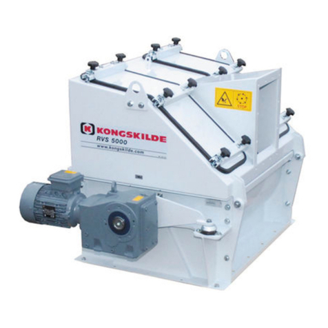
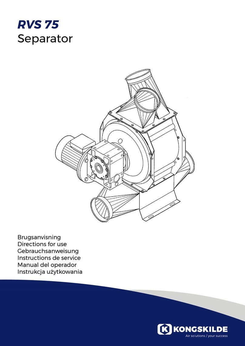
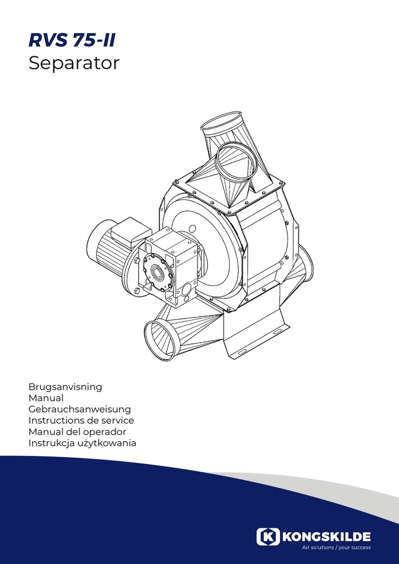
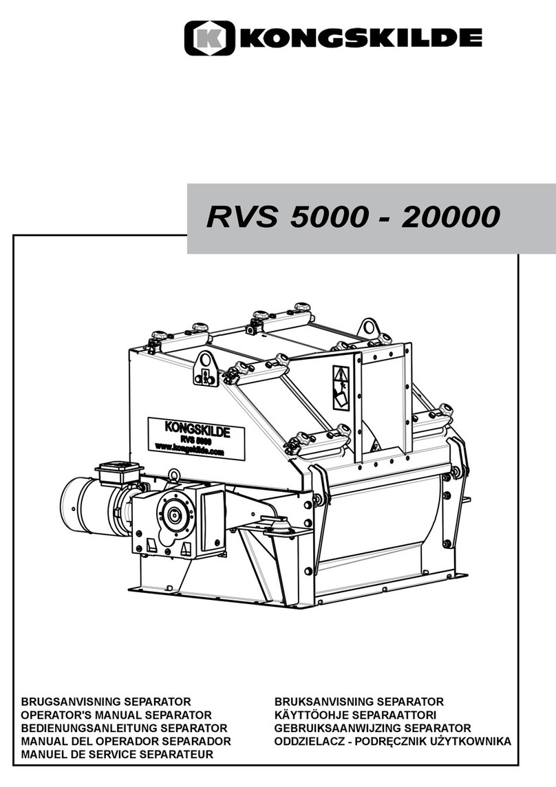
Kongskilde RVS 5000H Manual

RVS 5000H - 20000H
Rotary valve separator
Directions for use
Betriebsanleitung
Manuel de service
Instrucciones de funcionamiento
Podręcznik użytkownika
Brugsanvisning
Illustrationer for RVS brugsanvisning
RVS 2000 - 60000
121102942
Revision:

2
Illustrationer for RVS brugsanvisning
RVS 2000 - 60000
121102942
Revision:
GB
This user manual applies to the Kongskilde
RVS Separator model RVS 5000H, 10000H and
20000H.
Preface:
This users manual has been prepared in accordance
with EU-directive 2006/42/EC (Machinery Directive).
Marking:
See enclosed Declaration of Conformity.
Description:
The product is a separator designed to separate
conveying air from paper, cardboard, plastics or light
metal. The separator is driven by and directly coupled
to an electric geared motor. The rotor in the separator
is attached to the shaft of the geared motor, the mo-
mentum is transferred to the separators housing via a
momentum arm, and connected to a anged bearing at
the opposite end.
The rotor is supplied with replaceable rubber blades,
sealing segments and plastic edges. Furthermore, one
of the rotors´ 7 rubber blades is supplemented with a
scraper blade, which cleans the separator's sieve for
deposited material.
Typical application:
Separation of paper, card board and plastic materials.
The separator is not designed for moist or sticky mate-
rials, or hard materials and sheet thicknesses above 3
mm.
The separator can not be used to transport an endless
material, as this will block the rotor.
Warning notes:
Avoid accidents by always following the safety instruc-
tions given in the user manual and on the safety signs
located on the separator.
The separator must be installed in a closed duct sys-
tem, without access to rotating parts..
Any foreign objects allowed into the system, intention-
ally or unintentionally, may eventually damage the
separator.
Lack of supervision of the separator can result in wear
and/or damage to vital parts, see section "Service and
maintenance".
Due to friction, there will be transferred heat to the
outer casing of the separator during operation, which
will cause the casing to become hot by touch.
The mounting of the separator must be as prescribed,
if not, stability is reduced and wear and tear increased.
Material &
conveying
air inlet
Conveying
air outlet
Material outlet
Direction of
rotation

3
Ensure that all guards are intact and properly secured
during operation.
Always disconnect electricity to the separator prior to
repair and maintenance. The safety switch must be
switched off and locked to ensure, that the separator
cannot be started by mistake.
At any time prevent foreign bodies from being sucked
into the connected piping system - any metallic object
could cause sparks to be generated inside the sepa-
rator, with risk of dust explosion. Accordingly, avoid
ames or sparks from eg. an angle grinder being
sucked into the piping.
Never put your hand into the separator inlet or outlet
during operation.
The separator should be mounted in an accessible
location for maintenance. The working area around the
separator should be clear and trip free when carrying
out maintenance.
Make sure that there is adequate lighting when working
on the separator.
In cases where is it necessary to remove material
blocking the rotation, the safety switch must always be
switched off and locked in order to prevent start up of
the separator. If removal of material in the separator is
done while the power is switched on, the separator will
start as soon as the blocking material is removed. This
involves great risk of personal injuries!
In case of abnormal vibrations or noise, stop the sepa-
rator immediately and examine the cause. In case of
doubt, skilled assistance must be called in for repair
and maintenance.
Take care that the separator is securely installed, onto
a stable and at surface, a to avoid falling down and
tipping over.
Use eye protection when working close to the air outlet
of the separator. In case of small particles in the con-
veyed material, these might be blown from the air out-
let, causing eye damage.
The separator contains rotating parts, that should be
completely inaccessible by hands, unless the separate
lockable start/stop switch has been blocked, or the
separator is not electrically connected.
In case of any person contact with the rotating parts,
there is great risk of personal injury.
To avoid any unintentional contact with rotating parts,
pipes of minimum 800 mm length, with a diameter of
maximum Ø 200 mm must be installed onto the inlet
and outlet connections.
These pipes must be installed with bolt clamps, where
tools are necessary for dismantling.
In case it is not possible to use minimum 800 mm
tubes, it must be insured that there within minimum
800 mm from the separator are used bolt clamps,
where tools are necessary for dismantling.
The reason for this is, that according to EU-directive
2006/42/EC (Machinery Directive), it is not allowed for
any unauthorized personnel to gain access to rotating
parts. In case quick couplings are used, unautorized
personnel could dismantle the tubing, and have access
to rotating parts.
It is equally important, that the separator´s material
outlet is secured against access to the rotating parts.
There must be a vertical minimum distance of 2,7 me-
ters from the bottom of the container to the rotor, ac-
cording to DS/EN ISO 13857 : 2008 (Safety distances
to prevent hazard zones being reached by upper and
lower limbs), in order to avoid contact with the rotor
during operation. Thus, the separator must not be con-
nected before it is properly mounted on eg. a compac-
tor or a container.
Also note the risk of squeezing ngers, eg. between
gear motor torque arm / rubber bushing and xing to
the bottom of the separator. Likewise, there is a risk
of squeezing between the top and bottom eg. when
replacing rubber blades or by touching the separator
bearings during operation.
Warning signs:
Warning signs with symbols without text are found on
the separator. The symbols are explained below.
Read the user manual carefully and
observe the warning texts in the user
manual and on the separator.
Guards must not be opened or re-
moved while the separator is in opera-
tion. The moving parts of the separator
may not be touched, until they are
completely stopped.

4
Never put your hand into the separa-
tors intake or outlet while the separator
is in operation.
Location of lifting eyes for the separa-
tor.
Illustrationer for RVS brugsanvisning
RVS 2000 - 60000
121102942
Revision:
Illustrationer for RVS brugsanvisning
RVS 2000 - 60000
121102942
Revision:
Mounting:
The separator is lifted by the lifting eyes. Weight of the
separator; see section "Technical data".
It should be avoided that the separator outlet is clogged
or blocked with material as this may damage the sepa-
rator. If necessary, a level sensor can be installed under
the separator exit which interrupts the system upon
activation.
Operation in combination with cardboard, carton
and paper
Cover plates and corresponding bolts as well as nuts
on both sides of the rotor are removed (see illustration).
In addition, the supplied plugs must be placed in the
pipes, which are then secured with the bracket at-
tached by the two bolts. Finally, the air damper must be
removed to ensure that material does not accumulate
around the bearings, see the following section.
Operation in combination with plastic and metal foil
Cover plates and corresponding bolts as well as nuts
on both sides of the rotor are mounted (see illustra-
tion). Furthermore, the accompanying brackets and the
two plugs must be removed. Hereby, the vacuum in
the material inlet will suck an airow around the bear-
ings of the rotor, through the holes below the bearings.
Thereby the bearings are kept free from foil that could
eventually damage the bearings. Finally, the air damp-
ers on both bearings should be adjusted, see the sec-
tion below.

5
Adjustment of air damper (in combination with
plastic- and metal foil operation)
It is important that the bearings of the separator are
kept free of foil strips, as the strips will otherwise pack
around the bearings and eventually destroy the separa-
tor. The best way to prevent this, is to provide a con-
stant airow, that pulls strips that are forced past the
rotor sealing segments, away from the inside of the
separator around the bearings. The separator is there-
fore provided with air intake holes under the bearings,
which ensure an air ow that pulls foil strips in the pipe-
line under the rotor shaft, and back into the material
inlet, whereby the strips will enter the separator again.
To reduce this ow, the opening of the air intake holes
can be adjusted with a sliding damper (see illustration).
The damper is adjusted according to table 1 at the back
of this manual, by loosening the two locknuts and mov-
ing the damper underneath both bearings. The value Y
is measured manually between the slide damper and
the side of the separator.
Electrical installation:
The circuit must be completed by a qualied electri-
cian. He must ensure the installation of overload pro-
tection (the motor must never be connected to power
without it). He must also ensure the installation of a
no-voltage release relay so that the motor can never
restart automatically after a power failure.
In addition to the start/stop function normally incorporat-
ed in a system control panel, a separate lockable start/
stop switch as well as an emergency stop button must
be installed no more than 3 m from each separator.
The rst of these will prevent any unintentional start
during service. All local factory inspectorate regulations
must also be complied with.
The separator is supplied with unmounted motor,
as the direction of rotation must be checked before
starting.
When connecting the motor, proceed as follows:
1. The lid of the terminal box is removed and the mo-
tor is connected according to shown below
2. The power is connected, and the direction of rota-
tion is checked on the motor axle end or cooling fan
3. If the direction of rotation is OK, the motor is
mounted, if not, 2 phases are switched
4. Ret the terminal box lid
NB! It is very important that the motor is connected with
correct direction of rotation, as the rubber blades other-
wise fold the wrong way. Furthermore, there is a great
risk of deformation of the separator, if the rubber blades
are forced back in correct direction, by simply forcing
the rotor in proper direction of rotation. If the motor is
started in wrong direction of rotation, follow the instruc-
tions later in this section. The motor is therefore not
mounted upon delivery.
General notes regarding connection of 3 phase
asynchronous motors
If the power lines with phase sequences L2, L1 and
L3 are connected to the connection points U1, V1 and
W1 as shown below, the motor rotates anticlockwise,
viewed from the shaft end. The direction of rotation can
be changed by switching between 2 phases.
Star connection Delta connection
Y
Illustrationer for RVS brugsanvisning
RVS 2000 - 60000
121102942
Revision:
Sliding damper

6
A
B
DETAIL A (1 : 5)
DETAIL B (1 : 5)
Illustrationer for RVS brugsanvisning
RVS 2000 - 60000
121102942
Revision:
The rubber blades are turned the right way as fol-
lows:
1. The top of the separator is lifted (see section "Ser-
vice and Maintenance")
2. The motor is removed from the gear unit
3. The upper rubber blades are removed
4. The adapter attached to the torque arm is inserted
into the gear, whereby the rotor can be rotated with
a ratchet or cordless screwdriver. Rotate the rotor
until the lower rubber blades are turned upwards
and they have sprung out into place. All rubber
blades are reinstalled, during which the rotor is
continuously turned in correct direction of rotation
5. The adapter is removed and attached to the torque
arm with the screw
6. The motor is connected correctly and may be
started before re-assembly to check the direction of
rotation
7. The top of the separator is lowered and fastened
(see section "Service and Maintenance").
NOTE! Please note that if the rotor is attempted forced
in the correct direction of rotation with reversed rubber
blades, a large bias will occur in the rotor, and thus on
the ratchet, with risk of injury.
The adaptor is attached here
The adapter is
placed here
Below is an example of the motor label:
The above shown label indicates that at a nominal sup-
ply voltage of 400V / 50Hz, the motor must be connect-
ed to star connection. Furthermore, power consumption
is 156A (also applies to 480V / 60Hz).
The earthing terminal on the motor casing is intended
for potential equation, and does not replace the ground
terminal in the connection box.
Remember to connect the motor with sufcient cable to
allow the motor to be removed without disconnecting
the cable.
NB! In case the separator was started with incorrect
direction of rotation, the rubber blades will most likely
been folded in the wrong way. In this case, do not at-
tempt to rotate the rotor in the correct direction of rota-
tion as there is a great risk of deformation of the sepa-
rator bottom!
NOTE! Phase reversing the gear motor will not be able
to turn the rubber blades correctly, as the motor's per-
formance is too low.
A
DETAIL A (1 : 5)
Illustrationer for RVS brugsanvisning
RVS 2000 - 60000
121102942
Revision:
Direction of rotation

7
Spare adapters can be ordered under the following part
numbers:
Separator type Part no. Shaft diameter
RVS 5000 + 10000 121 102 630 Ø 24mm
RVS 20000 121 102 632 Ø 28mm
Start-up:
During any test operation, it is recommended to ap-
ply the supplied PTFE spray onto the inner side of the
separator, to avoid unnecessary wear of rubber blades
and sealing segments, and to reduce energy consump-
tion of the gear motor.
After commissioning of the system, including adjust-
ment of the sliding dampers according to the table at
the back of this manual, it is recommended to check
if the rotor bearings are kept clean for material. This
is done by lifting the upper part (see section "Service
and Maintenance") and checking the area at the rotor
bearings. If the material can be conveyed through the
system, at a given (low) air velocity, the sliding dampers
should be opened more, in case leaked material tends
to gather around the rotor axle inside the separator.
Prior to start-up, check:
• that there are no foreign objects in the separator
housing or the associated duct system
• that the direction of rotation of the separator's ro-
tor is correct (indicated by the arrow). The motor's
cooling fan and rotor axle in the motor side rotates
in a clockwise direction. See the rotor axle in oppo-
site side if in doubt
• the oil level in the gear
• that the rubber ring in the vent screw is removed
• that all parts, including protective guards, are se-
curely fastened
Operation:
If the separator is clogged or need inspection, the two
inspection hatches on the upper part can be removed.
This is done by loosening the thumb screws, and slid-
ing the pawls towards the centre of the hatch, where
after the hatch can be lifted away. At installation of
the hatch, it is important to ensure, that the gaskets
and pawls are correctly seated before tightening the
thumb screws. In case the hatch does not seal correctly
against the upper part, there is risk of dust pile-up or
other contamination of the separator.
Be careful not to squeeze ngers when handling the
hatches. If the separator is running in overpressure
installation, pay particular attention when handling the
hatches, as there may be a risk of lifting by the air pres-
sure, when they have been loosened. Always discon-
nect overpressure prior to disassembly.
Service and maintenance:
All service, maintenance and repairs should be per-
formed by qualied or trained personnel.
The separator is equipped with replaceable rubber
blades, sealing segments and plastic edges. The rub-
ber blades and segments run close to the separators
housing, and will be worn over time. The lifetime of the
blades and segments are dependent of the conveyed
material. When the rubber blades and segments are
worn, air will slip past the rotor, thereby hampering the
materials from falling out of the separator. When the
capacity has become too low, the rubber blades and
segments needs replacement.
In addition, worn rubber blades may cause foil to build
in the top of the separator. This foil will be held by the
blowers vacuum through the sieve holes, and may
eventually be wrapped around the rotor bearings and
destroy the rotor (see section "Installation").
Replacement of rubber blades and sealing seg-
ments
Always disconnect the power to the separator before
repair and maintenance. The safety switch must be
interrupted and locked so that the separator can not be
started by mistake. Also stop the corresponding blower.
The separator's top part can be raised by loosening
/ removing the pipe connections on both sides of the
separator and loosening the eye bolts (1). Thereafter
the upper part can be lifted by crane and wire or chain
in the lifting eyes (2), see illustration.
When the top part is fully lifted, remove the bolt (3) and
t into the locking position on both sides, after which
the wire or chain can be released.

8
The rubber blades (1) can be replaced by loosening the
M8 bolts and removing the steel plates. Be aware that
the chamfer of the blades is positioned correctly in rela-
tion to the direction of rotation, see illustration. To assist
the replacement, the motor can be removed, and the
adaptor inserted (see section "Electrical installation"),
whereby the rotor can be rotated manually.
1
3
2
Illustrationer for RVS brugsanvisning
RVS 2000 - 60000
121102942
Revision:
Should the sealing segments (2) also be replaced, do
this before re-mounting the rubber blades by loosening
the countersunk screws. Make sure the nuts on the rear
are correctly seated in the segment before tightening
the countersunk screws, see illustration.
The separator's top part is closed in the reverse order.
A
DETAIL A (1 : 2)
Illustrationer for RVS brugsanvisning
RVS 2000 - 60000
121102942
Revision:
.
.
.
.
2
1
3
3
Illustrationer for RVS brugsanvisning
RVS 2000 - 60000
121102942
Revision:

9
Adjustment / replacement of plastic edges
When the plastic edges (3) become worn, the rubber
blades are no longer able to touch the plastic edges,
and the lubricant is thus not distributed on the inside
of the separator. This can cause a soothing sound (de-
pending on the separated material).
When the edges are worn, they can be adjusted in-
wards against the rubber blades, by loosening the
screws on the underside, loosening the locknuts, and
tightening the adjustment screws on the steel bars of
the edges. The plastic edges must touch the rubber
blades, and can be adjusted both at standstill, and dur-
ing operation. They can be adjusted steplessly inwards
until the adjusting screws are fully inserted. Remember
to tighten the locknuts on the adjusting screws and the
screws on the underside.
When the plastic edges can no longer be adjusted
inward, they should be replaced - if necessary, in com-
bination with replacement of rubber blades and sealing
segments.
Be aware of the danger of squeezing when the separa-
tor top is lifted! Required clearance at lift to top, see
section "Technical data".
When replacing rubber blades, sealing segments and
plastic edges, use only genuine Kongskilde spare parts.
Please refer to the spare part list.
NB! When replacing rubber blades, scraper and seal-
ing segments, it is important to use the new included
self-locking screws. Otherwise, there is a risk that the
screws will loosen and fall into the material outlet.
Necessary lifting force for opening the separator top
Separator type Newton
RVS 5000 600
RVS 10000 1000
RVS 20000 2000
In addition, the internal parts of the separator, sieve
holes and duct piping are optimally cleaned with pres-
surized air.
If moist and / or sticky material has come into the sepa-
rator, further cleaning may be required.
The anged bearings are lubricated with a grease gun
in the grease nipples every 1.000 running hours, with a
good quality ball bearing grease, like SKF LGMT 2.
Be careful not to overll the bearings.
Lubrication of the gear:
The gear is provided with mineral oil, ISO VG 220, for
operation in a range of -10 to +40°C. At working tem-
peratures outside this area, synthetic oil can be used
with advantage.
Recommended synthetic oil types are for example:
Mobil SHC 630 or Shell Omala S4 GX 220
Gear oil is replaced the rst time after 300 hours of
operation, hereafter every 3 years for mineral oil, and
every 6 years for synthetic oil.
The oil level must be checked and possibly relled
every 3.000 hours of operation. Also check the gear for
oil leakage and condition of the sealings. Replace leaky
seals.
Oil is lled through the (upper) vent screw hole,
checked through the middle screw hole (located right
below the motor axle), and drained through the lower
screw hole.
The gear ventilates through the vent screw during tem-
perature uctuations.
The gear motor must be cleaned as needed to prevent
overheating.
Oil volumes:
Separator type Oil quantity litres
RVS 5000 L 1,1
RVS 10000 L 2,1
RVS 20000 L 3,7
RVS 5000 R 2,7
RVS 10000 R 4,6
RVS 20000 R 8,8

10
Troubleshooting:
Fault Cause Remedy
Abnormal noise from
the rubber blades
during operation
Incorrect adjustment of the plastic
edges
Foreign object in the separator
Adjust the plastic edges according to "Service and
maintenance"
Remove foreign object
Direction of rotation
reversed
Connection of phases reversed Connect L1, L2 and L3 correct, and ensure the rub-
ber blades are positioned correctly prior to start
Material has difcul-
ties from falling out
of the separator, or
the suctional effect
at productional loca-
tion reduced
Worn out rubber blades
Material is piled up in lumps
Material is not removed immedi-
ately on outlet side
Material fall velocity to low
Material is supplied in to large
amount
Renew rubber blades and sealing segments (and
possibly also plastic edges)
Composition of material should be modied at pro-
ductional location
Ensure sufcient emptying
Composition of material should be modied at pro-
ductional location
Material amount should be reduced
Separator will not
operate
Safety switch disconnected
Overload protection disabled due
to overheating
Missing signal from device control
unit
Fuses defect
Turn on safety switch
Refer to "Overload protection disabled due to over-
heating"
Check control unit
Locate cause of fuse malfunction and replace fuses
Motor protection
switched off due to
overheating
Foreign object in the separator
Rotor is frozen and stuck
Motor or gear defect
Rotor deformed
Overload protection incorrect
adjusted
Major decrease in voltage supply
Fuses defect
Remove foreign object
Defreeze with hot water or air
Replace gear motor
Replace rotor
Adjust correctly
Replace supply cables to larger cross section
Locate cause of fuse malfunction and replace fuses

11
Technical data:
RVS 5000H RVS 10000H RVS 20000H
Max. air volume 5.000 m3/h 10.000 m3/h 20.000 m3/h
Material amount (at 100 g/m2or 100 µm) * 1.200 kg/h 2.000 kg/h 4.000 kg/h
Max. negative pressure -25 kPa -20 kPa -15 kPa
Max. overpressure (cardboard, carton and paper) 5 kPa
Max. overpressure (plastics) 0 kPa
Hole size in sieve Ø3 mm
Max. material diagonal dimension** 300 mm 400 mm 600 mm
Min - max. material thickness (paper and carton)** 40 g/m2- 2.800 g/m2
Min - max. material thickness (corrugated card-
board)** 1 mm - 10 mm
Min / max. material thickness (plastic)** 10 µm - 3 mm
Min / max. material thickness (aluminium)** 15 µm - 300 µm
Max. height X 1.225 mm 1.600 mm 2.300 mm
Motor / gear 1,5 kW / 17 rpm. 1,5 kW / 11 rpm. 3,0 kW / 11 rpm.
Power supply
3 x 230/400V 50Hz
3 x 460V 60Hz
3 x 575V 60Hz
Weight 340 kg 600 kg 1.240 kg
Pressure loss See tabel in the back of this manual
Leak air
*: Material amount is indicative. For specic capacity, contact Kongskilde.
**: Indicative maximum material dimensions that can be expected to be separated, with non sticky or damp materi-
als. At plastic- and metal foil above 0,5mm thickness, the corresponding diagonal dimension is 150 mm.

12
Illustrationer for RVS brugsanvisning
RVS 2000 - 60000
121102942
Revision:
DE
Diese Betriebsanleitung gilt für die Kongskilde RVS
Separator model RVS 5000H, 10000H und 20000H.
Vorwort:
Diese Betriebsanleitung wurde entsprechend der
EU-Richtlinie 2006/42/EC (Maschinenrichtlinie) erstellt.
Markierung:
Siehe beigefügte Konformitätserklärung.
Beschreibung:
Bei dem Produkt handelt es sich um einen Separator,
konzipiert um Papier, Pappe, Kunststoff oder Leicht-
metall von der Förderluft zu trennen. Der Separator
wird von einem direkt-gekoppelten Elektrogetriebemo-
tor angetrieben. Der Rotor des Separators ist an der
Antriebswelle des Getriebemotors befestigt, und am
anderen Ende mit einem Flanschlager verbunden. Ein
Drehmomentarm überträgt das Drehmoment auf das
Separator-Gehäuse.
Der Rotor verfügt über auswechselbare Gummidicht-
lippen, Dichtungssegmente und Kunststofeisten.
Darüber hinaus wird eine der 7 Gummidichtlippen des
Rotors durch einen Abstreifer ergänzt, der das Sieb
des Separators von Materialablagerungen reinigt.
Anwendungsbeispiele:
Trennung von Papier, Pappe und Kunststoffen.
Für feuchte oder haftende/klebrige Materialien, oder
Hartstoffe und Blechstärken über 3mm ist der Separa-
tor nicht ausgelegt.
Der Separator kann nicht zur Förderung von Endlos-
materialien eingesetzt werden, da diese den Rotor
blockieren würden.
Warnhinweise:
Vermeiden sie Unfälle durch striktes Befolgen der in
dieser Betriebsanleitung aufgezeigten Sicherheitsvor-
schriften sowie der auf dem Separator angebrachten
Sicherheitsschilder.
Der Separator muss in einem geschlossenen Rohrsys-
tem – ohne Zugang zu rotierenden Teilen – installiert
werden.
Jegliche Fremdkörper, die beabsichtigt oder unbeab-
sichtigt in das System gelangen, können letztendlich
den Separator beschädigen.
Mangelhafte Kontrolle des Separators kann den Ver-
schleiß und/oder die Beschädigung wichtiger Teile zur
Folge haben, s. Abschnitt “Service und Wartung“.
Durch Reibung erzeugte Wärme wird während des
Betriebes auf das Außengehäuse des Separators
übertragen. Berühren sie daher nicht das Gehäuse, da
es heiß werden kann.
Material- und
Förderluft-
eintrittinlet
Förder-
luftaustritt
Materialaustritt
Drehrich-
tung

13
Die Montage des Separators muss gemäß Anleitung
erfolgen, um Stabilitätsverluste und Verschleiß zu ver-
meiden.
Stellen sie bitte sicher, dass alle Schutzvorrichtungen
während des Betriebes intakt und ordnungsgemäß
gesichert sind.
Unterbrechen sie vor Reparatur- und Wartungsarbei-
ten immer die Stromversorgung zum Separator. Der
Sicherheitsschalter muss ausgeschaltet und gesichert
sein, damit der Separator nicht versehentlich gestartet
werden kann.
Bewahren sie Fremdkörper grundsätzlich davor, in das
angeschlossene Rohrsystem gesaugt zu werden – je-
der Metallgegenstand kann zur Funkenbildung im In-
neren des Separators, und so zu einer Staubexplosion
führen. Vermeiden sie gleichermaßen, dass Flammen
oder Funken von z.B. einem Winkelschleifer in die
Rohrleitung gesaugt werden.
Fassen sie während des Betriebs niemals mit der Hand
in den Ein- oder Austritt des Separators.
Der Separator sollte an einem für die Wartung leicht
zugänglichen Ort montiert werden. Während einer War-
tung sollte der Arbeitsbereich um den Separator herum
sauber und stolperfrei sein.
Sorgen sie für angemessene Beleuchtung, wenn am
Separator gearbeitet wird.
Sind Materialverstopfungen, die die Rotation blockie-
ren, zu entfernen, muss der Sicherheitsschalter immer
ausgeschaltet und gesichert sein, um ein Anfahren des
Separators zu verhindern. Entfernt man einen Material-
stau während der Netzschalter eingeschaltet ist, startet
der Separator, sobald die Verstopfung entfernt wurde.
Dies birgt ein sehr hohes Verletzungsrisiko!
Treten ungewöhnliche Vibrationen oder Geräusche
auf, schalten sie den Separator unverzüglich aus und
suchen sie die Ursache. Im Zweifelsfall ist für die Repa-
ratur und Wartung fachkundige Unterstützung hinzuzu-
ziehen.
Sorgen sie dafür, dass der Separator auf einer stabilen
und ebenen Oberäche fest installiert wird, um ein Um-
stürzen oder Kippen des Gerätes zu vermeiden.
Tragen sie eine Schutzbrille, wenn sie nahe des
Luftaustritts des Separators arbeiten. Benden sich
im Fördergut feine Partikel, können diese aus dem
Luftaustritt geblasen werden und Augenverletzungen
verursachen.
Der Separator enthält rotierende Teile, die mit der Hand
nicht erreichbar sein sollten, sofern nicht der separate,
absperrbare START-/STOP-Schalter arretiert wurde,
und der Separator nicht elektrisch angeschlossen ist.
Kommt eine Person mit rotierenden Teilen in Kontakt,
ist die Verletzungsgefahr extrem hoch.
Um jeden unbeabsichtigten Kontakt mit rotierenden
Teilen zu verhindern, müssen an den Ein- und Austritts-
anschlüssen Rohre mit einer Mindestlänge von 800
mm und einem maximalen Durchmesser von Ø200 mm
montiert werden.
Diese Rohre sind mittels Schraubkupplungen zu mon-
tieren, für deren Demontage man Werkzeug benötigt.
Sollten mindestens 800 mm lange Rohre nicht ein-
gesetzt werden können, ist dafür zu sorgen, dass in
diesem Bereich – mindestens 800 mm vom Separator
entfernt – Schraubkupplungen zum Einsatz kommen,
für deren Demontage Werkzeug erforderlich ist.
Der Grund hierfür ist, dass unbefugtes Personal gemäß
EU-Direktive 2006/42/EC (Maschinenricht-linie) nie-
mals Zugang zu rotierenden Teile erhalten darf. Wür-
den Schnellverschlusskupplungen verwendet, könnte
unbefugtes Personal die Rohrleitung demontieren und
Zugriff auf rotierende Teile erlangen.
Es ist gleichermaßen wichtig, dass der Materialaustritt
des Separators gegen Zugriff auf rotierende Teile gesi-
chert wird.
Gemäß DS/EN ISO 13857:2008 (Sicherheit von Ma-
schinen - Sicherheitsabstände gegen das Erreichen
von Gefahrstellen mit den oberen und unteren Glied-
maßen) muss es zwischen dem Boden des Containers
und dem Rotor einen vertikalen Mindestabstand von
2,7 Metern geben, um während des Betriebes Kontakt
mit dem Rotor zu vermeiden. Der Separator darf daher
nicht angeschlossen werden, bevor er nicht ordnungs-
gemäß auf (z.B.) einem Verdichter oder Container
montiert wurde.
Bitte beachten sie, dass außerdem das Risiko von
Fingerquetschungen besteht – z.B. zwischen Drehmo-
mentarm des Getriebemotors / Gummimuffe und der
Bodenbefestigung des Separators.
Das Risiko, sich zu quetschen, besteht ebenfalls zwi-
schen Oberteil und Boden, wenn man z.B. die Gum-
midichtlippen des Rotors tauscht, oder während des
Betriebes die Lager des Separators berührt.
Warntafeln:
Am Separator benden sich Warntafeln mit textlosen
Symbolen. Diese Symbole werden nachstehend erläu-
tert
Lesen Sie die Betriebsanleitung sorg-
fältig und beachten sie die Warnhin-
weise darin sowie am Separator

14
Schutzvorrichtungen dürfen nicht ge-
öffnet oder entfernt werden, während
der Separator in Betrieb ist. Bis zu
ihrem vollständigen Stillstand dürfen
die beweglichen Teile des Separators
nicht berührt werden
Fassen sie niemals mit der Hand in
den Ein- oder Austritt des Separators,
während dieser in Betrieb ist
Position der Hebeösen am Separator
Montage:
Der Separator wird mittels der Hebeösen angehoben.
Gewicht des Separators: s. Abschnitt “Technische
Daten“.
Ein Verkleben oder Verstopfen des Separator-Austritts
mit Material sollte vermieden werden, da dies den Se-
parator beschädigen könnte. Falls erforderlich, kann
unter dem Separator-Austritt ein Füllstandsensor ins-
talliert werden, der das System bei Aktivierung unter-
bricht.
Betrieb zusammen mit Pappe, Karton und Papier
Abdeckbleche und dazugehörige Schrauben und Mut-
tern auf beiden Seiten des Rotors werden entfernt (s.
Abbildung). Dann werden beiden Stopfen in den Roh-
ren platziert und mittels der Klammer und zwei Schrau-
ben gesichert. Zum Schluss ist der Luftschieber zu
entfernen, um sicher zu gehen, dass sich um die Lager
herum kein Material ansammelt – s. nachfolgenden
Abschnitt.
Betrieb zusammen mit Kunststoff und Metallfolie
Abdeckbleche und dazugehörige Schrauben und Mut-
tern auf beiden Seiten des Rotors sind montiert (s.
Abbildung). Die zugehörigen Klammern und die beiden
Stopfen sind zu entfernen. Hierdurch wird das Vaku-
um im Materialeintritt einen Luftstrom um die Lager
des Rotors und durch die Löcher unterhalb der Lager
ansaugen. So bleiben die Lager frei von Folie, die sie
letztendlich beschädigen könnte. Zuletzt sollten die
Luftklappen auf beiden Lagern justiert werden, s. nach-
folgenden Abschnitt.
Illustrationer for RVS brugsanvisning
RVS 2000 - 60000
121102942
Revision:

15
Illustrationer for RVS brugsanvisning
RVS 2000 - 60000
121102942
Revision:
Justierung der Luftklappen (für den Betrieb mit
Kunststoff- und Metallfolien)
Es ist wichtig, die Lager des Separators frei von Foli-
enstreifen zu halten. Diese Streifen würden sich an-
dernfalls um die Lager herum festsetzen und schließ-
lich den Separator zerstören. Der beste Weg, das zu
vermeiden, ist die Erzeugung eines konstanten Luft-
stroms, der Streifen, die hinter die Dichtsegmente des
Rotors gedrängt werden, vom Inneren des Separators,
und somit von den Lagern wegzieht. Unter den Lagern
verfügt der Separator daher über Belüftungslöcher, die
für einen Luftstrom sorgen, der Folienstreifen in die
Rohrleitung unter der Rotorwelle und zurück in den
Materialeintritt zieht, wodurch die Streifen wieder in den
Separator gelangen.
Um diesen Durchuss zu reduzieren, lässt sich die
Öffnung der Belüftungslöcher mittels eines Schiebers
einstellen (s. Abbildung).
Gemäß Tabelle 1 am Ende dieser Betriebsanleitung
wird der Schieber justiert, indem man die beiden Kon-
termuttern löst und den Schieber unterhalb beider
Lager bewegt. Der Wert Y wird manuell zwischen dem
Schieber und der Seite des Separators gemessen.
Elektromontage:
Der Stromkreis muss von einer Elektrofachkraft ge-
schlossen werden. Diese muss für den Einbau eines
Überlastschutzes sorgen (ohne den der Motor nicht an
den Stromkreis angeschlossen werden darf). Weiterhin
ist ein Nullspannung-Relais zu installieren, so dass der
Motor nach einem Stromausfall nicht automatisch neu
starten kann.
In einem Abstand von nicht mehr als 3 Metern von
jedem Separator entfernt sind zusätzlich zu der übli-
cherweise in einer Systemsteuerung integrierten Start/
Stopp Funktion sowohl ein gesonderter, arretierbarer
Start/Stopp Schalter, als auch ein Not-Aus-Schalter zu
installieren.
Ersterer verhindert einen unbeabsichtigten Start wäh-
rend Servicearbeiten.
Die Werks- und baupolizeilichen Vorschriften vor Ort
sind ebenfalls einzuhalten.
Die Lieferung des Separators erfolgt mit nicht-mon-
tiertem Motor. Der Motor wird lose beigestellt, da
seine Laufrichtung vor Einschalten geprüft werden
muss.
Beim Anschließen des Motors gehen sie bitte wie
folgt vor:
1. Entfernen sie den Deckel des Klemmenkastens
und schließen sie den Motor wie unten dargestellt
an.
2. Legen sie die Spannungsversorgung an und prüfen
sie die Laufrichtung am Motorachsenende oder
Kühlgebläse.
3. Ist die Laufrichtung OK, montieren sie den Motor.
Falls nicht, tauschen sie 2 Phasen.
Y
Illustrationer for RVS brugsanvisning
RVS 2000 - 60000
121102942
Revision:
Schieber

16
4. Bringen sie den Klemmenkastendeckel wieder an.
NB! Es ist sehr wichtig, dass der Motor mit korrekter
Laufrichtung montiert wird, da sich die Gummidichtlip-
pen andernfalls in die falsche Richtung falten. Es be-
steht außerdem ein sehr großes Risiko, den Separator
zu deformieren, wenn man die Gummidichtlippen zu-
rück in die richtige Richtung drängt, indem man einfach
den Rotor in die korrekte Laufrichtung dreht. Wurde der
Motor in falscher Laufrichtung gestartet, folgen sie bit-
ten den Anweisungen weiter unten in diesem Abschnitt.
Aus diesen Gründen wird der Motor der Lieferung lose
beigestellt.
Allgemeine Hinweise bezüglich des Anschlusses
von Drehstrom-Asynchronmotoren
Werden die Leitungen mit den Phasenfolgen L2, L1
und L3 mit den Anschlüssen U1, V1 und W1 wie unten
dargestellt verbunden, dreht der Motor vom Wellenen-
de aus gesehen entgegen dem Uhrzeigersinn. Durch
das Wechseln zwischen 2 Phasen lässt sich die Rotati-
onsrichtung ändern.
Sternschaltung Dreieckschaltung
Hier ein Beispiel für ein Motor-Typenschild:
Das oben gezeigte Typenschild gibt an, dass der Motor
bei einer nominalen Versorgungsspannung von 400V /
50Hz als Sternschaltung anzuschließen ist. Außerdem
beträgt der Stromverbrauch 156A (gilt auch bei 480V /
60Hz).
Die Erdungsklemme auf dem Motorgehäuse ist für den
Potentialausgleich gedacht – sie ersetzt nicht die Er-
dungsklemme im Anschlusskasten.
Denken sie daran, den Motor mit ausreichend Kabel
anzuschließen, damit der Motor entfernt werden kann,
ohne das Kabel trennen zu müssen.
NB! Wurde der Motor in falscher Laufrichtung gestartet,
haben sich die Gummidichtlippen höchstwahrscheinlich
in falscher Richtung gefaltet. Versuchen sie in diesem
Fall bitte nicht, den Rotor in korrekter Laufrichtung
zu drehen, da das Risiko, den Separator-Boden zu
beschädigen, sehr hoch ist. ACHTUNG! Mittels eines
Phasentausches wird der Motor nicht in der Lage sein,
die Gummidichtlippen richtig herum zu drehen, da die
Motorleistung zu gering ist.
Die Gummidichtlippen werden wie folgt in die rich-
tige Richtung gedreht:
1. Das Oberteil des Separators wird aufgeklappt (s.
Abschnitt “Service und Wartung“)
2. Heben sie den Motor vom Getriebe
3. Entfernen sie die oberen Gummidichtlippen.
4. Der am Drehmomentarm angebrachte Adapter wird
in das Getriebe gesteckt, wodurch sich der Rotor
mittels einer Ratsche oder mit einem Akkuschrau-
ber drehen lässt. Drehen sie den Rotor, bis die
unteren Gummidichtlippen nach oben zeigen und in
ihre normale Position zurückgefedert sind. Setzen
sie die vorher entfernten Gummidichtlippen wieder
ein, während sie den Rotor kontinuierlich in die
richtige Richtung drehen
5. Entfernen sie den Adapter und befestigen sie ihn
mittels der Schraube am Drehmomentarm
6. Schließen sie den Motor korrekt an. Er sollte vor
Remontage gestartet werden, um die Laufrichtung
zu prüfen
7. Das Oberteil des Separators wird heruntergeklappt
und xiert (s. Abschnitt “Service und Wartung“)
A
DETAIL A (1 : 5)
Illustrationer for RVS brugsanvisning
RVS 2000 - 60000
121102942
Revision:
Drehrichtung

17
A
B
DETAIL A (1 : 5)
DETAIL B (1 : 5)
Illustrationer for RVS brugsanvisning
RVS 2000 - 60000
121102942
Revision:
ACHTUNG! Zwingt man den Rotor mit umgedrehten
Gummidichtlippen in die korrekte Laufrichtung, können
am Rotor große Spannungen auftreten, die sich auf die
Ratsche übertragen – es besteht Verletzungsgefahr.
NB! Wurde der Motor in falscher Laufrichtung gestartet,
haben sich die Gummidichtlippen höchstwahrscheinlich
in falscher Richtung gefaltet. Versuchen sie in diesem
Fall bitte nicht, den Rotor in korrekter Laufrichtung
zu drehen, da das Risiko, den Separator-Boden zu
beschädigen, sehr hoch ist. ACHTUNG! Mittels eines
Phasentausches wird der Motor nicht in der Lage sein,
die Gummidichtlippen richtig herum zu drehen, da die
Motorleistung zu gering ist.
Der Adapter wird hier befestigt
Der Adapter wird
hier eingesetzt
Ersatzadapter können unter folgenden Teilenummern
bestellt werden:
Separator Modell Teile Nr. Wellen-
durchmesser
RVS 5000 + 10000 121 102 630 Ø 24mm
RVS 20000 121 102 632 Ø 28mm
Inbetriebnahme:
Bei jedem Testbetrieb empehlt es sich, das mitgelie-
ferte PTFE-Spray auf die Innenseite des Separators
aufzutragen, um unnötigen Verschleiß der Gummidicht-
lippen und Dichtungssegmente zu vermeiden, und um
den Energieverbrauch des Getriebemotors zu senken.
Vor Inbetriebsetzung des Systems – einschließlich Jus-
tierung der Absperrklappen gemäß der Tabelle auf der
Rückseite dieser Betriebsanleitung – empfehlen wir zu
prüfen, ob die Rotorlager frei von Material sind. Dies er-
folgt durch Anheben/Kippen des Oberteils (s. Abschnitt
“Service und Wartung“) und Kontrolle des Bereiches
um die Rotorlager herum. Kann das Material mit einer
vorgegebenen (geringen) Luftgeschwindigkeit durch
das System gefördert werden, sollten die Absperrklap-
pen weiter geöffnet werden, falls ausgetretenes Mate-
rial dazu neigt, sich um die Rotorachse im Inneren des
Separators herum zu sammeln.
Bitte prüfen sie vor Inbetriebnahme:
• dass sich im Separator-Gehäuse oder der ange-
schlossenen Rohrleitung keine Fremdkörper ben-
den
• dass die Drehrichtung des Separator-Rotors
korrekt ist (wird durch Pfeil angezeigt). Das Mo-
tor-Kühlgebläse und die Rotorachse im Motor dre-
hen im Uhrzeigersinn. Schauen sie im Zweifelsfall
auf die gegenüberliegende Rotorachse
• den Ölstand im Getriebe
• dass der Gummiring in der Entlüftungsschraube
entfernt wurde
• dass alle Teile, einschließlich der Schutzabdeckun-
gen, sicher befestigt wurden
Betrieb:
Ist der Separator verstopft, oder ist eine Wartung er-
forderlich, lassen sich die beiden Inspektionslukende-
ckel auf der Oberseite entfernen. Hierzu löst man die
Flügelschrauben und schiebt die Sperrklinken in Rich-
tung Luken-Mitte. Danach kann die Luken-Abdeckung
abgehoben werden. Beim Einbau der Lukendeckel ist
es wichtig, darauf zu achten, dass die Dichtungen und
Sperrklinken korrekt positioniert sind, bevor man die
Flügelschrauben wieder anzieht. Dichtet die Luke nicht
richtig gegen die Oberseite ab, besteht die Gefahr,
dass sich Staub ansammelt, oder der Separator ander-
weitig verschmutz wird.
Seien sie vorsichtig, und klemmen sie sich im Umgang
mit den Luken-Abdeckungen nicht die Finger. Läuft
der Separator in einem Überdrucksystem, seien sie im
Umgang mit den Luken besonders aufmerksam – es
besteht die Gefahr, dass der Luftdruck die gelockerten
Lukendeckel anhebt. Sorgen sie stets dafür, dass vor
Demontage kein Überdruck anliegt.

18
Service und Wartung:
Sämtliche Service- und Wartungsarbeiten sowie Re-
paraturen sollten von geschultem, oder Fachpersonal
durchgeführt werden.
Der Separator ist mit austauschbaren Gummidichtlip-
pen, Dichtungssegmenten und Kunststofeisten be-
stückt. Die Gummidichtlippen laufen dicht am Separa-
tor-Gehäuse und nutzen sich im Laufe der Zeit ab. Die
Lebensdauer der Dichtlippen und der Segmente hängt
vom Fördergut ab. Sind Dichtlippen und Segmente
abgenutzt, gelangt Luft hinter den Rotor, wodurch die
Materialaustragung aus dem Separator behindert wird.
Ist die Leistung zu niedrig geworden, müssen die Gum-
midichtlippen und die Segmente ersetzt werden.
Abgenutzte Gummidichtlippen können zudem eine An-
sammlung von Folie im oberen Bereich des Separators
zur Folge haben. Diese Folie wird durch das Geblä-
se-Vakuum im Bereich der Sieblöcher festgehalten und
kann sich letztendlich um die Rotorlager wickeln und
den Rotor zerstören (s. Abschnitt “Montage“).
Austausch der Gummidichtlippen und der Dich-
tungssegmente
Unterbrechen sie vor Reparatur- und Wartungsarbei-
ten immer die Stromversorgung zum Separator. Der
Sicherheitsschalter muss ausgeschaltet und gesichert
sein, damit der Separator nicht versehentlich gestartet
werden kann. Stoppen sie ebenfalls das entsprechende
Gebläse. Das Oberteil des Separators lässt sich durch
Lösen / Entfernen der Rohrverbindungen auf beiden
Seiten des Separators sowie Lösen der Ringschrauben
(1) anheben. Danach kann das obere Teil per Kran
mit Hilfe einer durch die Hebeösen geführten Kette (2)
gekippt werden, s. Abbildung.
Ist das Oberteil vollständig angehoben bzw. gekippt,
lösen sie die Schraube (3) und setzten sie sie in die
Verriegelungsposition ein. Danach kann die Kette ge-
löst werden.
.
.
.
.
2
1
3
3
Illustrationer for RVS brugsanvisning
RVS 2000 - 60000
121102942
Revision:

19
1
3
2
Illustrationer for RVS brugsanvisning
RVS 2000 - 60000
121102942
Revision:
A
DETAIL A (1 : 2)
Illustrationer for RVS brugsanvisning
RVS 2000 - 60000
121102942
Revision:
Die Gummidichtlippen (1) lassen sich durch Lösen der
M8 Schrauben und Entfernen der Stahlplatten erset-
zen. Achten sie darauf, dass die Schrägkante der Plat-
ten in Bezug auf die Drehrichtung korrekt positioniert
ist, s. Abbildung. Um den Austausch zu vereinfachen
kann der Motor entfernt, und der Adapter eingesteckt
werden (s. Abschnitt “Elektromontage“), so dass sich
der Rotor manuell drehen lässt.
Sollen die Dichtungssegmente (2) ebenfalls ersetzt
werden, erledigen sie das vor Remontage der Gum-
midichtlippen, indem sie die Senkschrauben lösen.
Achten sie darauf, dass die Muttern auf der Rückseite
richtig im Segment sitzen, bevor sie die Senkschrauben
anziehen, s. Abbildung.
Das Oberteil des Separators wird in umgekehrter Rei-
henfolge geschlossen.
Justierung / Austausch der Kunststofeisten
Nutzen sich die Kunststofeisten (3) nach und nach ab,
können die Gummidichtlippen nicht länger die Kunst-
stofeisten berühren, und das Schmiermittel wird so
nicht mehr auf der Innenseite des Separators verteilt.
Je nach abgeschiedenem Material kann dies ein Ge-
räusch hervorrufen.
Sind die Kunststofeisten abgenutzt, können sie ein-
wärts gegen die Gummidichtlippen gerichtet justiert
werden, indem man die Schrauben auf der Unterseite
sowie die Kontermuttern löst, und die Stellschrauben
auf den Stahlstäben der Kanten anzieht. Die Kunst-
stofeisten müssen die Gummidichtlippen berühren
und können sowohl während eines Stillstands, als auch
während des Betriebes justiert werden. Sie lassen sich
schrittweise einwärts justieren, bis das Ende der Ver-
stellmöglichkeit erreicht ist. Denken sie daran, die Kon-
termuttern auf den Stellschrauben und die Schrauben
an der Unterseite wieder anzuziehen.
Lassen sich die Kunststofeisten nicht länger einwärts
justieren, sollten sie ausgetauscht werden – falls erfor-
derlich gemeinsam mit den Gummidichtlippen und den
Dichtungssegmenten.
Denken sie daran – es besteht Klemm-/Quetschgefahr,
wenn das Separator-Oberteil angehoben wird! Das
hierbei gewünschte Abstandsmaß entnehmen sie bitte
dem Abschnitt “Technische Daten“.
Wenn sie Gummidichtlippen, Dichtungssegmente und
Kunststoffkanten ersetzen, verwenden sie bitte aus-
schließlich Kongskilde Original-(Ersatz-)Teile gemäß
der Ersatzteilliste.
NB! Wenn sie die Gummidichtlippen, den Abstreifer
und die Dichtungssegmente erneuern, ist es sehr
wichtig, die neuen, den Ersatzteilen beigefügten selb-
sthemmenden Schrauben zu verwenden. Sonst besteht
das Risiko, dass sich die Schrauben lösen und in den
Materialaustritt fallen.
Erforderliche Hebekraft, um den Separator-Deckel zu
öffnen:
Separator Modell Newton
RVS 5000 600
RVS 10000 1000
RVS 20000 2000
Zudem lassen sich die Innenteile des Separators, die
Sieblöcher sowie die Rohrleitung mittels Druckluft opti-
mal reinigen.
Ist feuchtes und / oder haftendes Material in den Sepa-
rator gelangt, ist möglicherweise eine zusätzliche Reini-
gung erforderlich.

20
Die Flanschlager werden alle 1.000 Betriebsstunden
mittels einer Schmierpistole und mit Wälzlagerfett von
guter Qualität (z.B. SKF LGMT 2) in den Schmiernip-
peln abgeschmiert.
Seien sie vorsichtig, dass die Lager nicht überfüllt wer-
den.
Getriebeschmierung:
Das Getriebe ist mit Mineralöl versehen, ISO VG 220,
bereit zum Einsatz in einer Umgebung mit einer Tem-
peratur von -10 bis +40°C. Bei Betriebstemperaturen
außerhalb dieses Bereiches sollte synthetisches Öl
verwendet werden.
Empfohlene Synthetik-Öl-Sorten sind zum Beispiel:
Mobil SHC 630 oder Shell Omala S4 GX 200
Das erste Mal ist das Getriebeöl nach 300 Betriebs-
stunden zu wechseln, danach alle 3 Jahre bei Mine-
ralöl, und alle 6 Jahre, wenn synthetisches Öl im Ein-
satz ist.
Alle 3000 Betriebsstunden ist der Ölstand zu prüfen
– eventuell ist Öl nachzufüllen. Untersuchen sie das
Getriebe auch auf Ölleckagen und prüfen sie die Dich-
tungen. Ersetzen sie fehlerhafte Dichtungen.
Öl wird durch die (obere) Entlüftungsschraubenöffnung
eingefüllt, durch das mittlere Schraubenloch (direkt
unter der Motorachse) geprüft, und durch das untere
Schraubenloch abgelassen.
Bei Temperaturschwankungen lüftet das Getriebe durch
die Entlüftungsschraube.
Der Getriebemotor ist zu reinigen und vor Überhitzung
zu schützen.
Ölmenge:
Separator Modell Ölmenge Liter
RVS 5000 L 1,1
RVS 10000 L 2,1
RVS 20000 L 3,7
RVS 5000 R 2,7
RVS 10000 R 4,6
RVS 20000 R 8,8
This manual suits for next models
2
Table of contents
Languages:
Other Kongskilde Water Filtration System manuals