Benutzer- und Sicherheitshinweise
Vielen Dank, dass Sie sich für ein Qualitätsprodukt von inVENTer entschie-
den haben.
Diese Montageanleitung gibt Ihnen einen Überblick über ihr Produkt und
den sicheren Umgang mit ihm. Ein Symbol auf der linken Seite und ein
Signalwort vor dem Text kennzeichnen Sicherheits- und Warnhinweise:
GEFAHR: Schwerer Personenschaden oder Tod droht unmittelbar.
VORSICHT: Leichter/mittlerer Personenschaden droht unmittelbar.
HINWEIS: Sachschaden droht unmittelbar oder möglicherweise.
sMove: Bezugnahme auf die beiliegende Montageanleitung sMove
Sicherheitshinweise
Diese Montageanleitung ist nur zusammen mit der Montage- und
Bedienungsanleitung für die Regler sMove s4 und sMove s8 gültig
und ergänzt sie. Auch für dieses Dokument gelten alle rechtlichen Hinweise,
die in der Montage- und Bedienungsanleitung sMove s4 / sMove s8 aufge-
führt sind, uneingeschränkt
Lesen Sie sich vor der Montage des Reglers die Montageanleitung
sorgfältig durch und beachten Sie alle in diesem Kapitel aufgeführ-
ten Hinweise zur Montage. Beachten Sie darüber hinaus die Sicherheitshin-
weise, die den beschriebenen Handlungsanweisungen vorangestellt sind
und alle Sicherheitshinweise, die in den Dokumenten zum sMove s4 und
sMove s8 aufgeführt sind. Die Nichtbeachtung von Sicherheitshinweisen
kann zu Personen- und/oder Sachschäden führen.
GEFAHR: Beachten Sie beim Verlegen des Netzanschlusskabels
die Vorgaben der Schutzklasse II. Trennen Sie vor Arbeiten an
elektrischen Anlagen alle betroffenen Geräte von der Stromversorgung. Die
Netzstromversorgung muss den Angaben des Typschildes entsprechen.
Verlegen Sie Kabel nicht unter Spannung. Kontrollieren Sie vor dem Anbrin-
gen der Wandöffnungen ob elektrische Leitungen im Bohrbereich verlaufen.
Die Installation darf nur durch qualifiziertestes Elektrofachpersonal erfolgen.
Produktbeschreibung
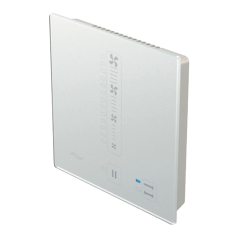
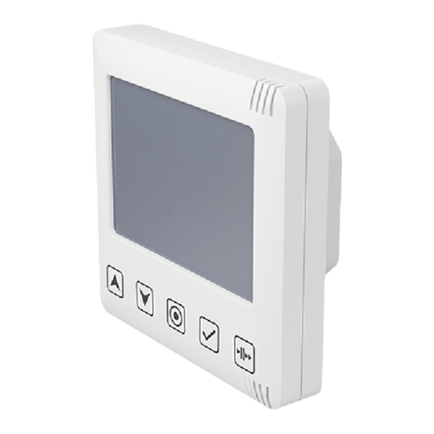
Der Regler sMove ist ein elektronisches Bediengerät zur Ansteuerung
der inVENTer-Lüftungsgeräte mit Wärmerückgewinnung. Er ist in den
Varianten s4 und s8 erhältlich.
Bei der Version „Long“ handelt es sich um eine zusätzliche Ausführung.
Sie eignet sich insbesondere beim Umbau bereits vorhandener Regler
mit Doppelkammer-Dose oder wenn beim sMove s8 mit Unterputz-
Schaltnetzteil nur eine Dose verwendet werden soll.
Der Regler sMove s4/s8 Long gleicht in Aufbau, Bedienung und Funktion
dem sMove s4 bzw. sMove s8.
Weitere Informationen zum Regler sMove entnehmen Sie der beiliegen-
den Montage- und Bedienungsanleitung Regler sMove (sMove).
TIPP: Ersetzt der Regler sMove s4/s8 Long einen bereits
vorhandenen Regler, beachten Sie zusätzlich die Demontageanlei-
tung Regler. Diese finden Sie unter www.inventer.de/downloads.
Fahren Sie nach der Demontage mit Schritt 2, Unterputz-Schaltnetzteil
anschließen, auf der Rückseite fort.
Product overview
The sMove controller is an electronic operating unit for controlling inVENTer®
ventilation devices with heat recovery. It is available in the sMove s4 and
sMove s8 versions.
The sMove s4/s8 Long is an additional version. It is especially designed for
replacement of existing controllers with a 2-cavity box and if the controller
sMove s8 is installed in only one box.
Structure, operation and function is analogous to sMove s4/s8 controller.
For detailed information see the enclosed installation and operating manual
(sMove).
TIP: If the controller sMove s4/s8 Long replaces an existing controller, see
the disassembling manual for our controllers at www.inventer.de/downloads.
In this case after disassemly skip installation step 1 and continue with installation step 2
(Connect the flush mounted switching PSU) on the documents back side.
Elektrischer Anschluss
Wiring
GEFAHR: Offen liegende elektrische Komponenten.
Stromschlag/Verletzung durch spannungsführende Bauteile (230 V, 50 Hz)!
►Vor Arbeiten an elektrischen Anlagen betroffene Geräte von der
Stromversorgung trennen.
► Vorgaben der Schutzklasse II beim Verlegen des Netzanschlusskabels beachten.
►Kabel nicht unter Spannung verlegen oder anschließen.
►Ventilator-BUS und Netzanschlusskabel getrennt verlegen.
►Montage und Anschluss nur von qualifiziertem und geschultem Personal.
HINWEIS:
Keine Funktion des Reglers.
Beachten Sie die notwendigen Leitungsquerschnitte, maximale Kabel-Längen
und Anschlussbelegungen (siehe sMove, Kapitel 4, Seite 11 ff.)
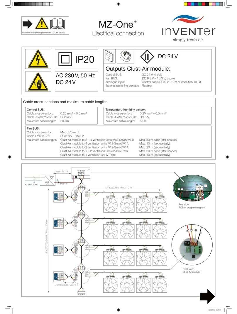
Anschlussbeispiel Regler sMove, Version Long
Connecting example sMove controller, long version
Bauteile / Components
1 Stecker-BUS 4.0 / BUS connector 4.0
2 Reversier-Ventilator / Reversible fan
3 Dose für Bedieneinheit, 2 Kammern (Doppeldose Hohlwand) /
mounting box for operating unit, 2 cavities (flush mounted dual box)
4 Verbindungsklemmen / Terminal blocks
5 Rückseite Bedieneinheit / Rear view of operating unit
6 Steckbrücke externe Schnittstelle / Jumper for external interface
7 Steckbrücke für Service-Einstellungen/ Jumper for service settings
8 Anschlussklemme, 2-polig (Externe Schnittstelle) /
Terminal, 2-pole (external interface)
9 Anschlussklemme, 5-polig (Ventilator-BUS/ Betriebsspannung Regler)
Terminal, 5-pole (fan BUS/ controller operating voltage)
10 Unterputz-Netzteil NT17-s4 / Flush mounted PSU NT17-s4
DANGER: Exposed electrical components.
Electric shock and injury due to live components (230V, 50Hz)!
►Before working on electrical installations, disconnect all affected equipment
from the power supply.
► Observe the requirements for protection class II when laying the mains cable.
► Do not lay or connect live cables.
►Lay the fan BUS and power cables separately.
►Installation and connection must only be performed by qualified personnel.
NOTE
Controller without function.
Observe the necessary wire cross-sections, maximum cable lengths and connector
assignments (see sMove, section 4, page 11 ff.).
Beachten Sie die folgende Vorgehensweise vor der Montage:
•Schalten Sie das Gerät spannungsfrei.
•Sichern Sie das Gerät gegen Wiedereinschalten.
•Prüfen Sie das Gerät auf Spannungsfreiheit.
User and safety information
Thank you for purchasing this high quality product from inVENTer!
This instruction provides an overview of the product and the basic safety precau-
tions for safe and proper operation. A symbol on the left side of the instruction and
a signal word in front of the text indicate the safety and warning instructions as well
as its hazard level:
DANGER: indicates direct danger of serious injury or death.
CAUTION: indicates possible danger of minor/significant injury.
NOTE: indicates imminent or possible damage to property.
sMove: Reference to the enclosed sMove manual
Safety warnings
These installation instructions are only valid in conjunction with the
installation and operating instructions for the sMove s4/s8 controller, which
it supplements. All legal notices that are listed in the documentation for the sMove
s4/s8 controller, also apply to this document without restriction.
Read the operating instructions carefully before installing the sMove s4/s8
controller and observe all information provided in this section. Also note
the safety instructions that precede the described handling instructions and the safety
warnings in the enclosed sMove documentation. Non-observance of safety warnings
could result in injury and/or property damage.
DANGER: when laying the power supply cable, observe the requirements
of protection class II. Do not lay live cables. The mains power supply
must correspond to the specifications on the device type plate. Before working on
electrical installations, disconnect all affected equipment from the power supply.
Before fitting the wall openings, check for the presence of cables in the drilling area.
Installation, electrical connection and commissioning may only be performed by
qualified personnel.
Observe the following steps before mounting the sensor:
Step 1: Disconnect all affected equipment and live parts from power supply.
Step 2: Secure the controller against being switched on again.
Step 3: Check the disconnected parts for voltage/ Verify safe isolation.
III
IV
V
III
IV
III
IV
V
III
IV
V
L
PE
N
AC
DC II
II
II
III
IV
V
1
2
III
IV
V
Abbildung 1: Anschlussbeispiel Regler sMove s4 inkl. Unterputz-Schaltnetzteil
Figure 1: Connection example sMove s4 controller with ush mounted PSU
1
2
3
4
5
8
9
10
6
7
