manuals.online logo
Brands
  1. Home
  2. •
  3. Brands
  4. •
  5. Invertek Drives
  6. •
  7. DC Drive
  8. •
  9. Invertek Drives Optidrive HVAC Installation and operating instructions

Invertek Drives Optidrive HVAC Installation and operating instructions

Application note AN-ODV-2-025
28 April 2014
AN-ODV-2-025 Remote Push-button Speed Control
1
Optidrive Applications Support Library
Application Note
AN-ODV-2-025
Title
Remote Push-button Speed Control
Related Products
Optidrive HVAC
Level
1
1 –Fundamental - No previous experience necessary
2 –Basic –Some Basic drives knowledge recommended
3 –Advanced –Some Basic drives knowledge required
4 –Expert –Good experience in topic of subject matter recommended
Overview
For some applications it can be preferable to control the speed of a motor by increasing and decreasing speed using push-button
controls mounted on a control panel or operator station, sometimes referred to as Digital Potentiometer Speed Control. This
application note describes two examples of how this can be implemented on the Optidrive HVAC.
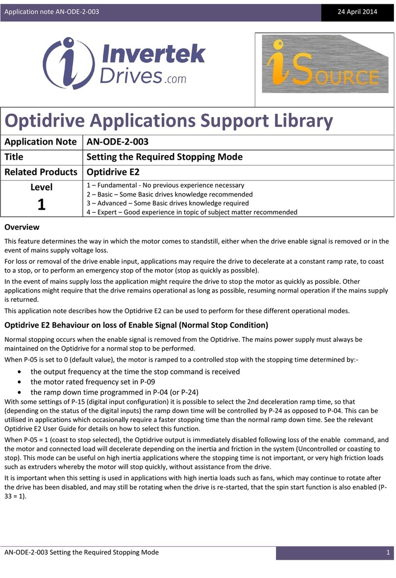
Solution One Wiring Diagram
The Following circuit uses a standard single pole switch for start and stop control with momentary push buttons to increase and
decrease speed.
Solution One Operation
The optional lock off provides a useful feature which stops operation of all of the other input functions and prevents operation
of the drive when in the open position. It could be provided as a key switch or a lock off on the control panel. The start mode for
the drive is set to edge triggered so that the start input must always be applied after the control lock-off is disabled (closed). If
this input is to provide a safety related input for the application then it must be configured as per the relevant safety standard to
the safety levels specified therein.
The Run/Stop input provides a Run command to the drive when the switch is in the closed position and a Stop when the switch
is open.
The Speed Up and Speed Down are momentary push buttons that are held in to increase or decrease the speed reference to the
drive.
The Fwd / Rev switch is optional depending on whether bi-directional (forward and reverse) motor rotation is required. The
drive operates in the forward direction when the switch is open and reverses when the switch closes.
Application note AN-ODV-2-025
28 April 2014
AN-ODV-2-025 Remote Push-button Speed Control
2
Solution One parameter Set-up
The drive should be defaulted back to factory settings prior to set-up. The following parameters are set within the drive to
activate the functionality shown in the control diagram. Check all parameters have been set correctly prior to enabling the drive.
Note that Parameter P1-14 must be set to the value listed in the table before access will be permitted to menu 2 and 9
parameters.
Parameter Changes:
Par
Description
Value
Par
Description
Value
P1-13
Digital inputs function select
0
P9-18
Speed select input 0
Off
P1-14
Extended Menu Access code
201
P9-19
Speed select input 1
Off
P2-36
Start Mode Select
Edge-r
P9-28
Remote up input source
Din-2
P9-06
Reverse enable
Din-4
P9-29
Remote down input source
Din-3
P9-10
Speed source 1
D-Pot
Menu 9 Reference (Parameter remaining at Default):
Par
Description
Value
Par
Description
Value
P9-01
Enable input source
Din-1
P9-09
Terminal ctrl override source
On
P9-02
Fast stop input source
Off
P9-11 –P9-17
Speed Source Reference 2 - 8
Not Applicable
P9-03
Run (FWD) input source
Din-1
P9-20
Speed select input 2
Off
P9-04
Run (REV) input source
Off
P9-21 –P9-23
Preset Speed Selection
Not Applicable
P9-05
Latch function enable
Off
P9-24 –P9-27
Ramp Selection
Not Applicable
P9-07
Reset input source
Din-1
P9-30 –P9-31
Speed Limit Switches
Not Applicable
P9-08
External Trip input source
Off
P9-32 –P9-41
PID and Output Functions
Not Applicable
The above table is included as a reference so the full configuration of menu 9 can be observed.
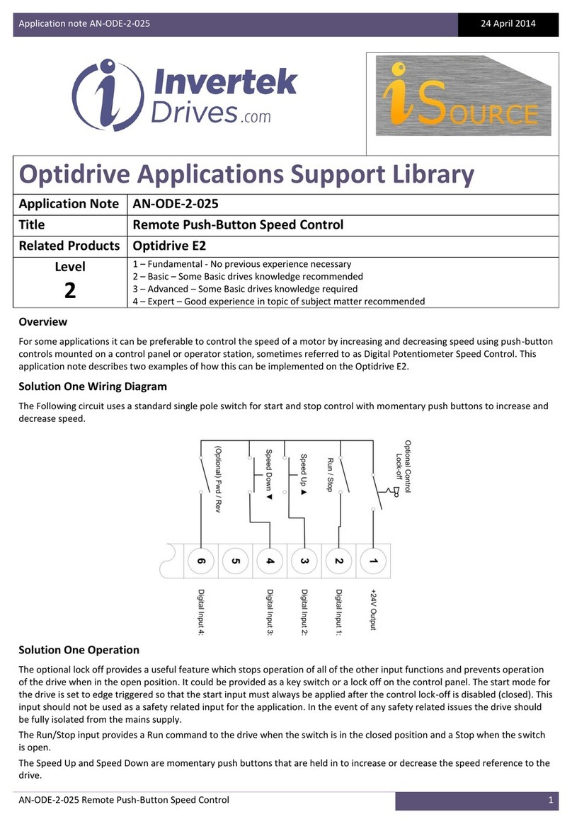
Solution Two Wiring Diagram
The Following circuit uses a standard momentary switches for start and stop control and for the push buttons to increase and
decrease speed.
Solution Two Operation
Fully detail of the optional lock off is provided in solution one operation description.
The Stop input is a normally closed momentary switch that provides a stop command to the drive when opened. The drive will
stop when this switch is activated (opened) and will prevent the drive starting whilst held in the open position. The switch is a
normally closed configuration to help protect against wire-break in the control circuitry.
The Start input is a normally open momentary switch that provides a Run command to the drive when the switch is closed. The
input is latched so that the switch can be released once the drive is started and will continue to run until over-written by a stop
input.
The Speed Up and Speed Down are momentary push buttons that are held in to increase or decrease the speed reference to the
drive.
The Fwd / Rev switch is optional depending on whether bi-directional (forward and reverse) motor rotation is required. The
drive operates in the forward direction when the switch is open and reverses when the switch closes.
Application note AN-ODV-2-025
28 April 2014
AN-ODV-2-025 Remote Push-button Speed Control
3
Solution Two parameter Set-up
The drive should be defaulted back to factory settings before the following parameters are set within the drive. Check all
parameters have been set correctly prior to enabling the drive.
Note that Parameter P1-14 must be set to the value listed in the table before access will be permitted to menu 9 parameters.
Parameter Changes:
Par
Description
Value
Par
Description
Value
P1-13
Digital inputs function select
0
P9-10
Speed source 1
D-Pot
P1-14
Extended Menu Access code
201
P9-18
Speed select input 0
Off
P2-36
Start Mode Select
Edge-r
P9-19
Speed select input 1
Off
P9-03
Run (FWD) input source
Din-2
P9-28
Remote up input source
Din-3
P9-05
Latch function enable
On
P9-29
Remote down input source
Din-4
P9-06
Reverse enable
Din-5
Menu 9 Reference (Parameter remaining at Default):
Par
Description
Value
Par
Description
Value
P9-01
Enable input source
Din-1
P9-11 –P9-17
Speed Source Reference 2 - 8
Not Applicable
P9-02
Fast stop input source
Off
P9-20
Speed select input 2
Off
P9-04
Run (REV) input source
Off
P9-21 –P9-23
Preset Speed Selection
Not Applicable
P9-07
Reset input source
Din-1
P9-24 –P9-27
Ramp Selection
Not Applicable
P9-08
External Trip input source
Off
P9-30 –P9-31
Speed Limit Switches
Not Applicable
P9-09
Terminal ctrl override source
On
P9-32 –P9-41
PID and Output Functions
Not Applicable
The above table is included as a reference so the full configuration of menu 9 can be observed.
Notes on Remote Push-button Speed Control:
The rate of change of the set-point is pre-set within the drive to match the ramp rates set in P1-03 (acceleration ramp) and P1-
04 (deceleration ramp) and cannot be adjusted independently. Therefore, as the ramp rate parameters are increased /
decreased, the rate of change of the motor set-point is correspondingly altered. The frequency shown on the drive display
should match closely the drive output speed to the motor at any given time.
The momentary push buttons for increasing and decreasing the speed set-point are mirrored by the up and down push buttons
on the drive keypad. The Stop / Start keypad buttons have no effect on drive operation unless the drive is configured in keypad
over-ride mode. The start / stop push buttons on the keypad are disabled for normal operation.
If both speed set-point push buttons (increase and decrease) are operated simultaneously then the decrease speed button will
over-ride the functionality of the increase speed push button and the speed set-point will decrease.
Appendix
Revision History
Issue
Comments
Author
Date
01
Document Creation
JP
08/02/12
02
Updated to new format
KB
28/04/14

Other Invertek Drives DC Drive manuals

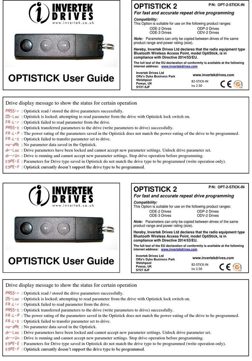
Invertek Drives OPTISTICK 2 User manual

Invertek Drives

Invertek Drives OPTISTICK 2 User manual

Invertek Drives Optidrive E2 Installation and operating instructions

Invertek Drives

Invertek Drives Optidrive E2 Installation and operating instructions

Invertek Drives OPTIDRIVE E3 User manual

Invertek Drives

Invertek Drives OPTIDRIVE E3 User manual

Invertek Drives Optidrive ODV-3-560540-3012-TN User manual

Invertek Drives

Invertek Drives Optidrive ODV-3-560540-3012-TN User manual

Invertek Drives Eco Optidrive Series User manual

Invertek Drives

Invertek Drives Eco Optidrive Series User manual

Invertek Drives Optidrive iE3 User manual

Invertek Drives

Invertek Drives Optidrive iE3 User manual

Invertek Drives Optidrive E2 Installation and operating instructions

Invertek Drives

Invertek Drives Optidrive E2 Installation and operating instructions

Invertek Drives Optidrive HVAC Installation and operating instructions

Invertek Drives

Invertek Drives Optidrive HVAC Installation and operating instructions

Invertek Drives Optidrive E2 Installation and operating instructions

Invertek Drives

Invertek Drives Optidrive E2 Installation and operating instructions

Invertek Drives Optidrive ODE-2-11005-1H01 Series User manual

Invertek Drives

Invertek Drives Optidrive ODE-2-11005-1H01 Series User manual

Invertek Drives Optidrive HVAC Installation and operating instructions

Invertek Drives

Invertek Drives Optidrive HVAC Installation and operating instructions

Invertek Drives Optidrive ODE-2-12005-1H01 01 Series User manual

Invertek Drives

Invertek Drives Optidrive ODE-2-12005-1H01 01 Series User manual

Invertek Drives Optidrive E2 Installation and operating instructions

Invertek Drives

Invertek Drives Optidrive E2 Installation and operating instructions

Invertek Drives OPTIDRIVE P2 Series Guide

Invertek Drives

Invertek Drives OPTIDRIVE P2 Series Guide

Popular DC Drive manuals by other brands

i-MO WD-L Installation and operating manual

i-MO

i-MO WD-L Installation and operating manual

KEBCO COMBIVERT F5 instruction manual

KEBCO

KEBCO COMBIVERT F5 instruction manual

KB Electronics Penta Power KBVF Series Installation & operation manual

KB Electronics

KB Electronics Penta Power KBVF Series Installation & operation manual

GE AF-600 FP Series Design guide

GE

GE AF-600 FP Series Design guide

ISOMET RFA741 Series instruction manual

ISOMET

ISOMET RFA741 Series instruction manual

Orion 7822 instruction manual

Orion

Orion 7822 instruction manual

Fuji Electric Frenic lift Reference manual

Fuji Electric

Fuji Electric Frenic lift Reference manual

ABB ACS880-01+C135 Series Supplement

ABB

ABB ACS880-01+C135 Series Supplement

PI PIFOC N-725.2A Technical notes

PI

PI PIFOC N-725.2A Technical notes

YASKAWA E7B T Series manual

YASKAWA

YASKAWA E7B T Series manual

FIBRO Movitrac 07B Additional instructions

FIBRO

FIBRO Movitrac 07B Additional instructions

Becker C01a Assembly and operating instructions

Becker

Becker C01a Assembly and operating instructions

SEW-Eurodrive MOVIMOT MM D Series Compact operating instructions

SEW-Eurodrive

SEW-Eurodrive MOVIMOT MM D Series Compact operating instructions

Pepperl+Fuchs HiC2883 manual

Pepperl+Fuchs

Pepperl+Fuchs HiC2883 manual

Danaher Motion Superior SLO-SYN SS2000MD4-M installation instructions

Danaher Motion

Danaher Motion Superior SLO-SYN SS2000MD4-M installation instructions

EUCHIPS EUP200AD-1H12V-0 quick start guide

EUCHIPS

EUCHIPS EUP200AD-1H12V-0 quick start guide

S&P REB CVF manual

S&P

S&P REB CVF manual

ETC F-Drive R12 Series installation manual

ETC

ETC F-Drive R12 Series installation manual

manuals.online logo
manuals.online logoBrands
  • About & Mission
  • Contact us
  • Privacy Policy
  • Terms and Conditions

Copyright 2025 Manuals.Online. All Rights Reserved.