Invicta SNL48V30GC User manual

SNL48V30GC User Manual

CONTENTS
1. Safety.............................................................................................................................................................1
1.1 Instruction ...........................................................................................................................................................1
1.2 Standard ..............................................................................................................................................................1
1.3 Important safety information .........................................................................................................................1
1.4 Battery Maintenance ......................................................................................................................................2
1.5 Waste Treatment................................................................................................................................................2
2. Introduction to the Invicta 48V Golf Cart battery ...........................................................................2
2.1. Key Features...................................................................................................................................................2
2.2. Product Appearance ....................................................................................................................................2
2.3 Functional characteristics.................................................................................................................................3
3. Installation....................................................................................................................................................4
3.1 Tool And Equipment .........................................................................................................................................4
3.2. Battery placement ........................................................................................................................................4
3.3 Supporting parallel connection ......................................................................................................................5
3.4 Connection mode of battery communication port ....................................................................................6
4. Charging requirements .............................................................................................................................7
4.1Charging with an AC-DC Battery Charger.....................................................................................................7
4.2Charging with Solar............................................................................................................................................7
4.3Charging with an Alternator via a DC-DC Charger .....................................................................................7
4.4 Recommended charging voltage ...................................................................................................................7
4.5 Equilibrium ......................................................................................................... Error! Bookmark not defined.
5 Battery Recyclable .......................................................................................................................................8

V0
1
1. Safety
1.1 Instruction
Please read the user manual carefully before installation, operation and maintenance, and pay attention to
various warning boards and warning statements on the equipment. Please keep it for future reference after
reading the user manual,
1.2 Standard
The following marks are used in the user manual to indicate where the special attention should be paid during
operation.
Marked Symbol
Expound
CAUTION, WARNING: Call attention to something
DANGER: Warning of electric shock risk
INSTRUCTION, HINT: It’s need to be special instructions or hints
1.3 Important safety information
The following operating and maintenance instructions must be read before installing, operating or maintaining
the battery.
Before installation :
•It is very important and necessary to read the user user manual carefully before installing or using the
battery. Failure to follow any of the instructions or warnings in this document can result in electrical
shock, serious injury, or may damage the battery and the whole system.
•Before connecting the battery packs to your equipment, check the voltages and ensure that they are
within the limits of your equipment specifications. Failure to observe these specifications could void your
warranty.
•We recommend charging each battery to 100% prior to installation.
Installation :
•We recommend using a golf cart technician when installing the battery. For best safety, follow the steps
described in this manual
•The ambient conditions given in the product documentation must be observed.

V0
2
Operating the battery /:
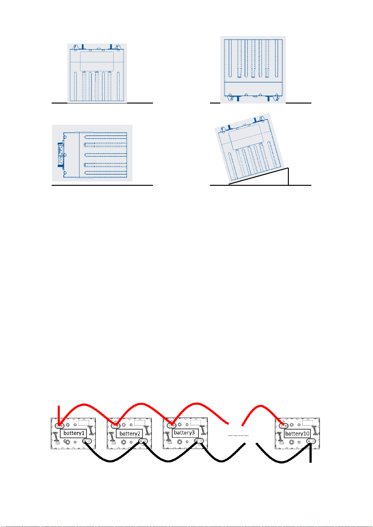
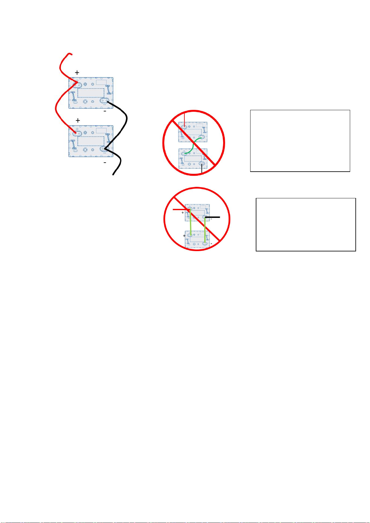
•It is prohibited to connect the battery with a different type of battery;
•A Invicta Lithium Charger with matching required voltage must be used;
•Long term floating charge is prohibited for lithium ion batteries
•The ambient conditions given in the product documentation must be observed.
•Keep the battery away from fire or water.
1.4 Battery Maintenance
•During the charging process, ensure that the plug and socket is connected, that the charging equipment
works normally, and that the connection points of the battery pack are in good contact. In case of
abnormality, it needs to be repaired before charging;
•If there is a large amount of dust, metal chips or other sundries on the upper cover and terminals of the
battery pack, clean it with compressed air. Avoid cleaning with water or water soaked objects;
•When charging and discharging, try to avoid splashing water or other conductive objects on the upper
cover and terminals of the battery, such as being exposed to heavy rain.
•Estimate the charging time and discharging time of the battery according to the actual use state of the
battery or battery pack. At the end of charging and discharging, pay attention to observe whether there
are abnormalities in the battery or battery pack.
•Once a month, check whether terminals and other nodes are loose, falling off, rusted or deformed, so as
to ensure the series and parallel connection of the battery pack.
1.5 Waste Treatment
Please dispose of the package and replaced parts according to the rules
applicable in the country where the device is installed.
Do not dispose the battery with normal domestic waste.
2. Introduction to the Invicta 48V Golf Cart battery
2.1.Key Features
•LiFePO4 composition – provides exceptional safety and longevity
•High safety and reliability
•Consistent performance over wide temperature range
This battery has accelerated passive cooling and can maintain a high current charge and discharge for a
longer time.
This battery can communicate with external devices through CAN and Bluetooth to better manage the battery.
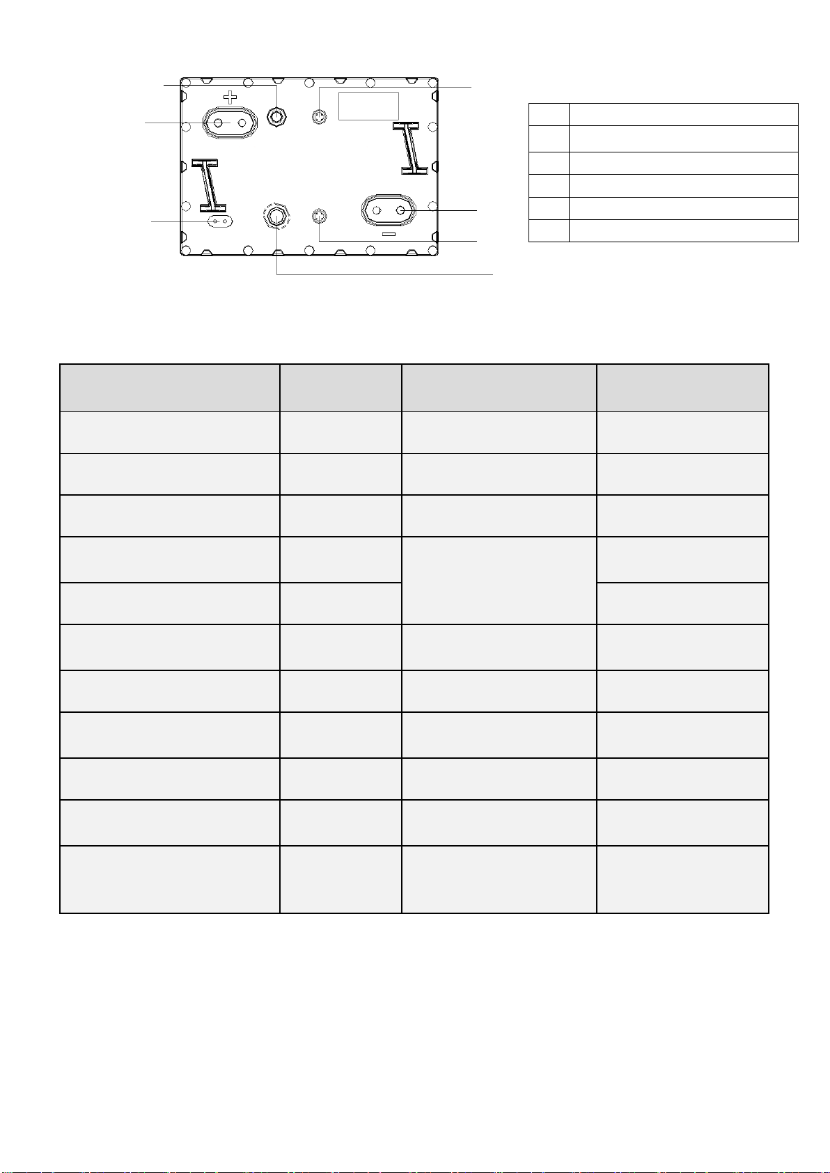
2.2.Product Appearance

V0
3
Fig1 Outline drawing
2.3 Functional characteristics
Item
Specification
Item
Specification
Rated voltage
51.2V
Size
260*180*272mm
Rated capacity
30AH
Communication
CAN/RS485
Standard Charging voltage
55.2V~57.6V
Weight
~15.5KG
Max continuous charging
current
30A
Working temperature
Charger :0℃-45℃
Standard charging current
10A
Discharge:-20℃-65℃
Maximum continuous
discharge current
60A
Short circuit protection
500A/366ms@close
battery
Peak discharge current / time1
65A/30S
Self discharge rate
<3%/month
Peak discharge current / time2
100A/10S
Cycle life
6000times@80%DOD
25℃
Discharge cut-off voltage
44.8V
Shell material
ABS+PC /UL94-V0
IP Grade
IP67
Pack certification
UL2271/CE/UN38.3/Class
9
Series and parallel connection
Max.10pcs battery
parallel , series
is not allowed.
Cell certification
UL1642/UL2580/UN38.3
2.3.1 First use
•When the battery leaves the factory, the isolation switch will be turned off and in the off state,
•Before use, the switch needs to be switched to the on state, and the LED indicator lights up.
•Before multiple batteries are connected in parallel, a multimeter shall be used to test the voltage at both
ends of the positive and negative poles of the battery to ensure that the voltage difference between the
batteries does not exceed 2V.
•If the voltage difference between batteries exceeds 2V, each battery shall be fully charged separately and
then used in parallel.
1.
Positive and negative terminals
2.
Explosion proof valve
3.
Communication port1
4.
Communication port2
5.
Isolation Switch
6.
LED
①
①
④
②
⑥
③
⑤

V0
4
2.3.2 LED description
``LED indicator, one red and one green
The red light indicates that a fault is displayed. Under normal conditions, the indicator is not on. When a fault
occurs, the indicator is on. The green light indicates different SOC according to different blinking modes.
SOC
Lighting mode
≤20%
On "0.3s" / off "0.7s"
20%-90%
On "1s" / off "1s"
≥90%
Green light constant
2.3.3 Communication port
•2 communication ports, with CAN communication and RS485 communication;
•The battery can be upgraded through the communication port
•It can communicate with other devices through the communication port, and the communication protocol
needs to be deployed before communication
2.3.4 ON or OFF
Invicta 48V GOLF CART has an isolation switch. When the battery is transported or stored for a long time,
this can be turned off. This ensures there is very low self-discharge, so the battery can be stored for a
long time and improve the safety of the battery.
3. Installation
3.1 Tools And Equipment
Insulating Gloves Safety Shoes Spanner
3.2.Battery placement
Gently place the battery pack on the support surface with the front side up, do not place it on the side or
upside down, and do not place any covering above the pack. The schematic diagram of battery pack
placement is shown in Figure 3

V0
5
Fig 3 Battery placement
3.3 Parallel Connections
INVICTA 48V GOLF CART allows up to 10 batteries to be used in parallel. Before parallel connection of
batteries, use a multimeter to test the voltage at both ends of the positive and negative electrodes of the
batteries, and ensure that the voltage difference between batteries does not exceed 2V. If the voltage
difference between batteries exceeds 2V, each battery shall be fully charged separately and then used in
parallel.
1. Precautions for parallel connection
A. The parallel battery pack must have the parallel function; The parallel connected battery packs must be
products of the same model and part number.
B. Ensure the length of all parallel wires is consistent;
C. We suggest using 0.5C for charging, that is, charging current=battery rated capacity * 0.5C
D. When the battery packs are used in parallel, the open circuit voltage of each group of batteries must be
highly consistent. It is recommended that the voltage difference between battery packs be:
Voltage difference < 2000mV (@ 0%~95% SOC)
When the voltage difference is less than 1500mV (@ 96%~100% SOC), the battery pack will be charged and
discharged as a whole after being connected in parallel. If one of the batteries needs to be replaced, it is
recommended that all battery packs be replaced at the same time
✔
✘
✘
✘

V0
6
Two 51.2V batteries rated at 30Ah connected in parallel
System Voltage: 51.2V
System Capacity: 30Ah + 30Ah = 60Ah
3.4 Connection mode of battery communication port
1.CAN
The battery includes a Controller Area Network (CAN) bus communication interface. Two round M8 DIN
connectors are located on the top of the battery to connect one battery to the other using CAN bus cables in a
simple daisy chain format.
The CAN bus function is not required for normal battery operation. Automatic operation and protection of
battery; It does not require any CAN bus communication or external devices (such as external controllers) or
other batteries connected to the CAN bus to work. Keep the two black covers installed on the two M12
connectors to protect them from the environment when not in use.
On-site service can retrieve the battery use history and view the status through the can bus interface for
diagnostic assistance.
! Do not use the battery in
series, which may permanently
damage battery.
! Do not output positive and
negative poles on the same
battery, which may damage the
battery.

V0
7
Each group of batteries is equipped with a special communication line, which is connected by CAN busthis
ensures the battery can communicate with the load or charger for more efficient use of the battery. This
alsocan allow a service assistant to better understand the battery failure. If you have more questions about
the CAN bus, please contact Invicta's engineers for technical support.
4. Charging requirements
We recommend using an Invicta Lithium Charger that meets the charging requirements below for maximum
performance and lifespan of the INVICTA series battery.
Model
Max
Charge
Voltage
Cut-off
Voltage
Maximum
Charge Current
Recommended
Charge Current
Operation
Temperature
48V
57.6V
40V
1C
0.3C
Charge: 0~45℃
Discharge: -20~65℃
4.1Charging with an AC-DC Battery Charger
Check the AC-DC battery charger you intend to use has a dedicated lithium charge setting that meets the
above charging requirements. A lot of battery chargers are designed for charging lead-acid batteries only and
may not have a suitable charge setting for lithium. If unsure always contact an expert for advice.
4.2Charging with Solar
Check the solar regulator you intend to use has a dedicated lithium charge setting that meets the above
charging requirements. A solar regulator without a lithium charge setting may be used to charge the INVICTA
series battery. However, it must be set to charge no higher than 58.4V and then MUST be switched off once
the INVICTA series battery is fully charged. DO NOT leave a solar regulator switched on without a suitable
lithium charge setting once the battery is fully charged.
4.3Charging with an Alternator via a DC-DC Charger
Check the DC-DC Charger you intend to use has a dedicated lithium charge setting that meets the above
charging requirements. A DC-DC charger without a lithium charge setting may be used to charge the INVICTA
series battery. However, it must be set to charge no higher than 58.4V and then MUST be switched off once
the INVICTA series battery is fully charged. DO NOT leave a DC-DC charger switched on without a suitable
lithium charge setting once the battery is fully charged.
4.4 Recommended charging voltage
The recommended charging voltage is set between 55.2V and 57.6V. It is strongly recommended an Invicta
Lithium Charger is used to charge the battery.
Fuel Gauge

V0
8
5. Battery Monitoring (wired/wireless)
To monitor your battery information there are two options available which connect to the CAN
communication ports.
1. Invicta digital CAN monitor (wired)
The Invicta digital monitor gauge can be connected to a CAN communication port on one of
your batteries via a wired connection. The gauge can then be installed in a suitable location which is
easily visible to the user.
2. Invicta Bluetooth CAN monitor
The Invicta CAN Bluetooth monitor device can be connected to one of the CAN ports on your batteries. When
used conjunction with the Invicta app, the battery information can be displayed on your mobile device, such
mobile phones or tablets via Bluetooth connection.
Note: The Invicta digital CAN monitor and Invicta Bluetooth CAN monitor can be used simultaneously.
For more information on monitoring options or assistance please contact the Sealed Performance Batteries
team
6. Battery Recyclable
Invicta® 48V GOLF CART Lithium-Ion batteries are recyclable and should not be disposed of as household or
landfill waste. If you need assistance in recycling your battery, contact your dealer or Invicta’s technical
support engineers as outlined at the front of this manual.
7. Contact Details and Other Information
A range of resources can be found at https://www.invictalithium.com.au/. This includes specifications, product
registration and our warranty statement. If you require any further assistance with your Invicta battery, please
contact the team at Sealed Performance Batteries (SPB) on 07 3886 1102 or [email protected]t.au.
Invicta is a trademark of Sealed Performance Batteries, a company that has over 25 years of experience in
energy storage and are located in Brisbane, Sydney and Melbourne. For more information on Sealed
Performance Batteries please visit https://www.sealedperformance.com.au/.
*Estimated ranges are guides only, and may vary dependent on the vehicle, environment and usage.
**Disclaimer: SPB will not accept liability for injuries to persons or damage to batteries/accessories or
customer's equipment due to the incorrect installation/handling of batteries or accessories.
*** For Club Car models older than 2014, you will need to complete a bypass of the onboard computer (OBC)
Table of contents
Other Invicta Batteries Pack manuals