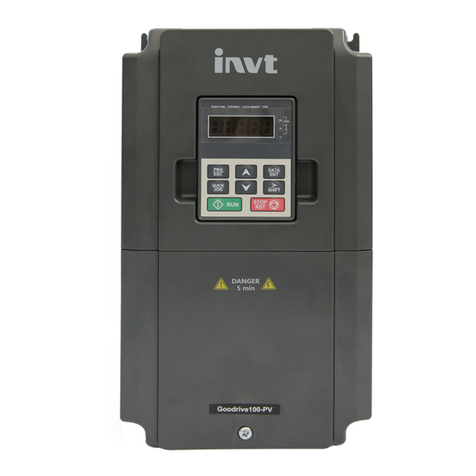
Goodrive300-LIFT series inverter Contents
iii
8.3 How to reset........................................................................................................................ 95
8.4 Fault history ........................................................................................................................ 95
8.5 Inverter faults and solutions................................................................................................. 95
8.6 Common fault analysis ...................................................................................................... 102
9 Maintenance and hardware diagnosis...................................................................................108
9.1 What this chapter contains ................................................................................................ 108
9.2 Maintenance intervals ....................................................................................................... 108
9.3 Cooling fan........................................................................................................................ 110
9.4 Capacitors..........................................................................................................................111
9.5 Power cable ...................................................................................................................... 112
10 Communication protocol...................................................................................................... 113
10.1 What this chapter contains .............................................................................................. 113
10.2 Brief instruction to Modbus protocol................................................................................. 113
10.3 Application of the inverter ................................................................................................ 114
10.4 RTU command code and communication data illustration ................................................ 119
10.5 Common communication faults........................................................................................ 134
Appendix A Expansion cards....................................................................................................135
A.1 What this chapter contains................................................................................................ 135
A.2 I/O expansion card............................................................................................................ 135
A.3 Asynchronous motor PG card ........................................................................................... 137
A.4 Synchronous motor PG card............................................................................................. 140
A.5 STO instructions ............................................................................................................... 143
Appendix B Technical data........................................................................................................151
B.1 What this chapter contains................................................................................................ 151
B.2 Ratings ............................................................................................................................. 151
B.3 Grid specifications ............................................................................................................ 152
B.4 Motor connection data ...................................................................................................... 152
B.5 Applicable standards......................................................................................................... 153
B.6 EMC regulations ............................................................................................................... 153
Appendix C Dimension drawings..............................................................................................155
C.1 What this chapter contains................................................................................................ 155
C.2 Keypad structure .............................................................................................................. 155
C.3 Inverter structure .............................................................................................................. 156
C.4 Dimensions for inverters of AC 3PH 380V(-15%)–440V(+10%) ......................................... 156
Appendix D Peripheral optional parts.......................................................................................158
D.1 What this chapter contains................................................................................................ 158
D.2 Peripheral wiring............................................................................................................... 158
D.3 Power supply.................................................................................................................... 159
D.4 Cables.............................................................................................................................. 159
D.5 Breaker and electromagnetic contactor............................................................................. 162
D.6 Reactors........................................................................................................................... 163
D.7 Filter................................................................................................................................. 164
D.8 Braking system................................................................................................................. 166
D.9 Emergency operation systems.......................................................................................... 168
Appendix E Further information................................................................................................169
