IONODES ATOMAS-DUO-HDMI User manual

ATOMAS-DUO-HDMI
User Manual
OEM Encoder Platform
Document Version 1.0

2
support@ionodes.com | www.ionodes.com
ATOMAS-DUO-HDMI
User Manual
©2010-2019, IONODES INC
All Rights reserved.
No part of this documentation may be reproduced or transmitted in any form or by any means, electronic,
photographic or mechanical, except as expressed in the Software License Agreement. IONODES shall not
be liable for technical or editorial errors or omissions contained herein. The information in this document
is subject to change without notice.
The information in this publication is provided “as is” without warranty of any kind. The entire risk arising
out of the use of this information remains with the recipient. In no event shall IONODES be liable for any
direct, consequential, incidental, special, punitive, or other damages whatsoever (including without
limitation, damages for loss of business profits, business interruption or loss of business information), even
if IONODES has been advised of the possibility of such damages and whether in an action or contract or
tort, including negligence.
This software and documentation are copyrighted. All other rights, including ownership of the software,
are reserved to IONODES Inc. All other brand and product names are trademarks or registered trademarks
of the respective owners.
The following words and symbols mark special messages throughout this guide:
Warning: Text set off in this manner indicates that failure to follow directions could result in damage to persons or
equipment.
Note: Text set off in this manner indicates special instructions which should be paid attention to.

3
support@ionodes.com | www.ionodes.com
Contents
1About the ATOMAS-DUO-HDMI ......................................................................................................................... 4
2Parts List ................................................................................................................................................................ 5
3Hardware Integration .......................................................................................................................................... 6
4Temperature Considerations ............................................................................................................................. 6
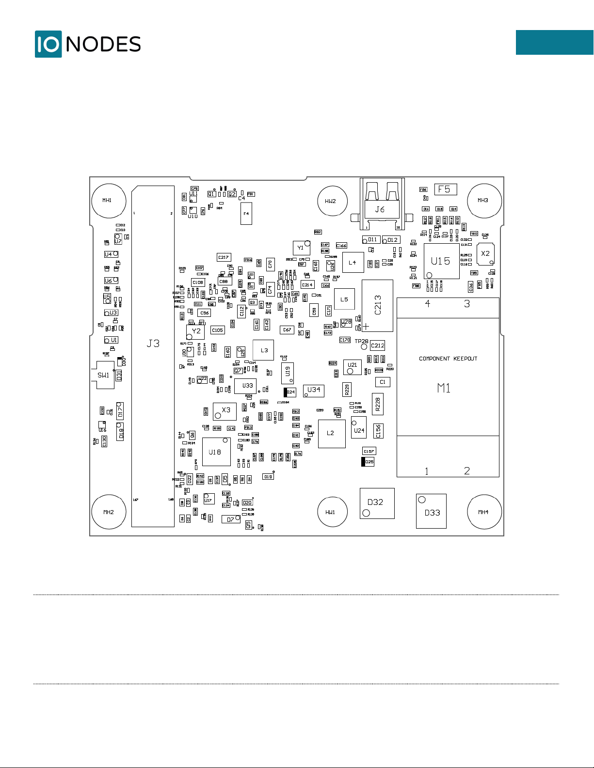
5ATOMAS-DUO-HDMI Carrier Board................................................................................................................... 7
5.1 Board layout.................................................................................................................................................. 7
5.2 Connector Part Numbers ............................................................................................................................ 9
5.2.1 J1 – Ethernet & Power In ....................................................................................................................10
5.2.2 J2 – Comm, GPIO & Audio ..................................................................................................................11
5.2.3 J5 – HDMI Video Interface..................................................................................................................12
5.2.4 J7 – Second Digital Video Interface...................................................................................................13
5.2.5 J10 – Analog Video Interface..............................................................................................................14
5.3 Understanding LED Status ........................................................................................................................15
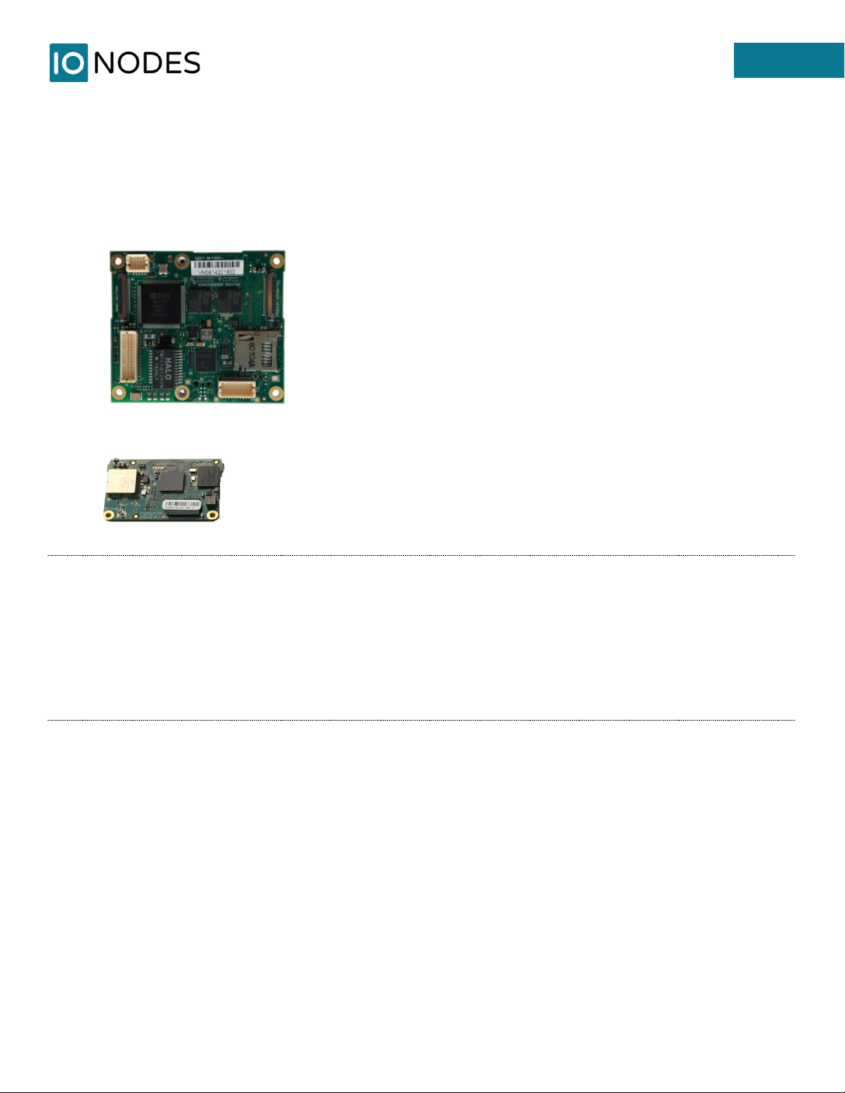
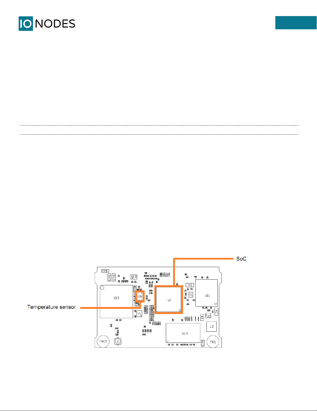
6ATOMAS-4K-SOM Processing Board ...............................................................................................................16
6.1 Board layout................................................................................................................................................16
6.2 Connector Part Numbers ..........................................................................................................................17
7ATOMAS-QUADSD-D656 ...................................................................................................................................18
7.1 Board layout................................................................................................................................................18
7.2 Connector Part Numbers ..........................................................................................................................19
7.2.1 J2 – BT.656 Video Output ...................................................................................................................20
8ATOMAS-MINI-BOSON-ADAPT .........................................................................................................................21
8.1 Board layout................................................................................................................................................21
8.2 Connector Part Numbers ..........................................................................................................................22
Annex - Statement Limited Warranty .....................................................................................................................23

4
support@ionodes.com | www.ionodes.com
1About the ATOMAS-DUO-HDMI
The ATOMAS-DUO-HDMI encoder platform is a feature-rich IP camera video encoder solution for a wide
range of single and multi-camera designs. The compact dual input form factor of the ATOMAS-DUO-HDMI
platform makes it especially well-suited for integration to dual camera systems with a HDMI zoom block
and a secondary video source (digital or analog) such as a thermal camera.
The ATOMAS-DUO-HDMI platform is designed for direct connection to the industry’s leading 4K HDMI zoom
blocks from SONY and other manufacturers. It is designed for simultaneous support of a secondary input
of digital / composite format, such as a thermal camera. Both cameras are processed simultaneously and
published via ONVIF and other IP APIs for streaming / recording.
The ATOMAS-DUO-HDMI platform features a powerful video codec engine capable of generating multiple
H.265 (HEVC) IP video streams at different quality settings. It can manage a primary video input at up to 4K
UHD resolution at 30fps; in dual input mode it can manage a secondary input at up to Full HD (1080p) at
30 fps.
The ATOMAS-DUO-HDMI platform offers multiple options, add-on modules and accessories designed to
allow you to leverage the same powerful video encoder platform in all of your single input and multi input
camera systems.

5
support@ionodes.com | www.ionodes.com
2Parts List
Qty Description
1 ATOMAS-DUO-HDMI Carrier Board
1 ATOMAS-4K-SOM (System-On-Module) Processing Board
Note: When unpacking, inspect the shipment box and appliance to identify any possible damages
due to shipping. Make sure all items have been delivered and that no items are missing.
Contact your Ionodes representative should you find any damages or defects.
Note: The product serial number label helps our product support team identify your device and its
factory configuration in the event that your IONODES product or its components require
service. The label is attached on the underside of the PCBA for both the Carrier Board as well
as the SOM.

6
support@ionodes.com | www.ionodes.com
3Hardware Integration
The ATOMAS-DUO-HDMI platform has been designed to allow for flexible hardware integration to existing
or new product designs. The ATOMAS-DUO-HDMI Carrier Board proposes four (4) mounting holes for
securing to your enclosure. In addition, a slight clearance around the board’s edge can also be used for
extrusion-type enclosures.
When integrating the ATOMAS-DUO-HDMI into a product design, position the module to allow for air
circulation around the board in order to maximize the chances of heat dissipation.
Warning: Be careful not to damage the module when using mounting screws.
4Temperature Considerations
The ATOMAS-DUO-HDMI platform has been designed with industrial temperature components (-40C to
+85C); however, reaching your temperature requirements may require that you add heatsinks to certain
board-level components which generate substantial heat.
The SoC and the temperature sensor are both placed on the SOM Processing Board. Their exact location
is depicted in the image below:

7
support@ionodes.com | www.ionodes.com
5ATOMAS-DUO-HDMI Carrier Board
5.1 Board layout
Figure 1 - ATOMAS-DUO-HDMI Carrier Board Top Side
Note: On the top side of the ATOMAS-DUO-HDMI Carrier Board there is a small physical button
labelled “SW1”, located next to the J3 connector. This button allows the user to perform a reset
to factory default settings. In order to do that the user must press and hold the button until the
status LED on the board changes to an alternating Red/Green pattern. Once it is released the
board will load default settings and restart automatically. A short press of the button (without
waiting for the Red/Green pattern) will only restart the board.

8
support@ionodes.com | www.ionodes.com
Figure 2 - ATOMAS-DUO-HDMI Carrier Board Bottom Side

9
support@ionodes.com | www.ionodes.com
5.2 Connector Part Numbers
•ATOMAS-DUO-HDMI Carrier Board
oJ1 – Ethernet & Power In / Hirose DF20F-30DP-1V(56)
oJ2 – Comm, GPIO & Audio / Hirose DF20F-20DP-1V(56)
oJ3 – B2B Connector for SOM
oJ7 – Second Digital Video Interface / KEL USL00-30L
oJ5 – HDMI Video Interface / KEL USL00-30L
oJ6 – microHDMI Video Interface
oJ8 – microSD Card Reader
oJ10 – Analog Video Interface / Hirose DF20F-10DP-1V(56)
Note: On the ATOMAS-DUO-HDMI Carrier Board, the second digital video interface (J7) and the analog
video interface (J10) cannot be used together at the same time. The user will have to choose the
active one via the encoder’s web management interface (may or may not require a reboot).
Note: On the ATOMAS-DUO-HDMI Carrier Board, the HDMI video interface (J5) and the microHDMI
video interface (J6) cannot be used together at the same time. The user will have to choose the
active one via the encoder’s web management interface (may or may not require a reboot).
Note: On the ATOMAS-DUO-HDMI Carrier Board the user can choose to have an optional PoE (Power-
over-Ethernet) module soldered onto the PCBA. Since this is done at the factory and the PoE
module cannot be removed or added later on, the user will need to explicitly specify it when
placing the order by selecting the appropriate option.

10
support@ionodes.com | www.ionodes.com
5.2.1 J1 – Ethernet & Power In
Hirose DF20F-30DP-1V(56)
Pin No.
Name
Comments
1
ETH_TRDD_P
Connects directly to RJ45 or network wiring
2
ETH_TRDC_N
Connects directly to RJ45 or network wiring
3
ETH_TRDD_N
Connects directly to RJ45 or network wiring
4
ETH_TRDC_P
Connects directly to RJ45 or network wiring
5
ETH_TRDA_P
Connects directly to RJ45 or network wiring
6
ETH_TRDB_N
Connects directly to RJ45 or network wiring
7
ETH_TRDA_N
Connects directly to RJ45 or network wiring
8
ETH_TRDB_P
Connects directly to RJ45 or network wiring
9
N/C
10
N/C
11
N/C
12
N/C
13
UART2_TX_EXT
1.6V to 3.6V
14
GND
15
UART2_RX_EXT
1.6V to 3.6V
16
GND
17
BACKUP_VBAT
18
ETH_LED_ACT
Connects directly to RJ45 or network wiring
19
GND
20
ETH_LED_SPEED
Connects directly to RJ45 or network wiring
21
CON_FACT_DFLT#
22
GND
23
GND
24
GND
25
3V3_100MA
3.3V DC Power Output (max. 100mA)
26
5V_500MA
5V DC Power Output (max. 500mA)
27
VIN
Input voltage: 7V to 17V
28
VIN
Input voltage: 7V to 17V
29
VIN
Input voltage: 7V to 17V
30
VIN
Input voltage: 7V to 17V

11
support@ionodes.com | www.ionodes.com
5.2.2 J2 – Comm, GPIO & Audio
Hirose DF20F-20DP-1V(56)
Pin
No.
Name
Comments
1
RS485_TX_R_P
2
RS485_RX_R_P
3
RS485_TX_R_N
4
RS485_RX_R_N
5
PWM2 Uses 3.3V Level. See SDK
documentation for control.
6
PWM1
Uses 3.3V Level. See SDK
documentation for control.
7
GND
8
PWM3
Uses 3.3V Level. See SDK
documentation for control.
9
AUDIO_LINE_OUT_LEFT
10
AUDIO_LINE_OUT_RIGHT
11
AUDIO_LINE_OUT_COMMON
12
I2C_data_signal
Uses 3.3V Level
13
GND
14
I2C_clock_signal
Uses 3.3V Level
15
CON_OUT
I/O output for dry contact output.
16
GND
17
CON_IN2
I/O input for dry contact input.
18
AUDIO_LINE_IN_RIGHT
19
CON_IN1
I/O input for dry contact input.
20
AUDIO_LINE_IN_LEFT

12
support@ionodes.com | www.ionodes.com
5.2.3 J5 – HDMI Video Interface
KEL USL00-30L
Pin No.
Name
Comments
1
GND
2
HDMIB_CLK_N
3
HDMIB_CLK_P
4
GND
5
HDMIB_DAT0_N
6
HDMIB_DAT0_P
7
GND
8
HDMIB_DAT1_N
9
HDMIB_DAT1_P
10
GND
11
HDMIB_DAT2_N
12
HDMIB_DAT2_P
13
GND
14
N/C
15
N/C
16
N/C
17
HDMIB_HPD
Hot Plug Detect
18
HDMIB_5V
+5V Power (output)
19
CAM_VBUS
USB_VBUS (input)
20
GND
21
CAM_USB2_N
22
CAM_USB2_P
23
GND
24
CAM0_CTL_RX/SCL
VISCA RxD (input)
25
CAM0_CTL_TX/SDA
VISCA TxD (output)
26
CAM0_RST#
Reset
27
DC_OUT
6-12V output to camera block. Sourced from
VIN with a 1.5A fuse.
28
DC_OUT 6-12V output to camera block. Sourced from
VIN with a 1.5A fuse.
29
DC_OUT
6-12V output to camera block. Sourced from
VIN with a 1.5A fuse.
30
DC_OUT
6-12V output to camera block. Sourced from
VIN with a 1.5A fuse.

13
support@ionodes.com | www.ionodes.com
5.2.4 J7 – Second Digital Video Interface
KEL USL00-30L
Pin No.
Name
Comments
1
CAM1_PWR
2
CAM1_PWR
3
GND
4
CAM1_DAT14
5
CAM1_DAT8
6
CAM1_DAT4
7
CAM1_DAT7
8
CAM1_RST#
9
CAM1_UART_RX
10
CAM1_DAT5
11
CAM1_DAT6
12
CAM1_DAT13
13
CAM1_UART_TX
14
CAM1_DAT15
15
CAM1_DAT10
16
CAM1_DAT12
17
CAM1_PIXCLK
18
CAM1_DAT9
19
CAM1_DAT11
20
CAM1_DAT2
21
GND
22
CAM1_VSYNC
23
CAM1_DAT3
24
CAM1_DAT1
25
CAM1_I2C1_SCL
26
CAM1_I2C1_SDA
27
CAM1_HSYNC
28
CAM1_DAT0
29
CAM1_FSYNC/DE
30
GND

14
support@ionodes.com | www.ionodes.com
5.2.5 J10 – Analog Video Interface
Hirose DF20F-10DP-1V(56)
Pin No.
ANALOG VIDEO INTERFACE TYPE
CVBS
S-VIDEO
YPrPb
1
N/C
N/C
N/C
2
N/C
N/C
Pr in
3
N/C
N/C
N/C
4
GND
GND
GND
5
GND
GND
GND
6
N/C
C in
Pb in
7
GND
GND
GND
8
GND
GND
GND
9
GND
GND
GND
10
CVBS in
Y in
Y in

15
support@ionodes.com | www.ionodes.com
5.3 Understanding LED Status
The status of the ATOMAS-DUO-HDMI is exposed via an on-board bi-color LED (Green/Red) placed onto
the Carrier Board. The following describes the system status LED mappings:
Normal Operation:
• Operating system boot up – LED is steady orange (max 30 seconds)
• Internal application startup – LED is flashing orange (2 second interval)
• System ready – LED is steady green
• Media streaming – LED is flashing green (1/2 second interval)
Special Operations:
• Identify command received – LED is flashing orange/green
• Reset to factory settings – LED is flashing rapidly red/green
• Software watchdog is rebooting the appliance – LED is flashing rapidly red
• Firmware update in progress – LED is flashing slowly red/green

16
support@ionodes.com | www.ionodes.com
6ATOMAS-4K-SOM Processing Board
6.1 Board layout
Figure 3 - ATOMAS-4K-SOM Processing Board Top Side
Figure 4 - ATOMAS-4K-SOM Processing Board Bottom Side

17
support@ionodes.com | www.ionodes.com
6.2 Connector Part Numbers
•J1 – Antenna U.FL Connector (50 Ohm, 6 GHz max frequency) / Hirose U.FL-R-SMT-1
•J2 – B2B Connector (towards ATOMAS-DUO-HDMI Carrier Board)
Note: The SOM offers the possibility of having a Wi-Fi chip onboard, allowing the encoder to be
managed and to stream video wirelessly. Since this is soldered onto the SOM’s PCB at the
factory, the user must explicitly specify the Wi-Fi option when placing the order. The chip cannot
be physically added or removed later on; however, the Wi-Fi functionality can be disabled in the
encoder’s web management interface.
Note: The SOM will interface with the ATOMAS-DUO-HDMI carrier board via the B2B connector.

18
support@ionodes.com | www.ionodes.com
7ATOMAS-QUADSD-D656
The ATOMAS-QUADSD-D656 module is a video interface add-on module, designed for use with the
ATOMAS-DUO-HDMI encoder platform. This optional module converts 4x Analog Composite (CVBS) input
video signals into a multiplexed BT.656 video signal that is fed to the second digital input of the ATOMAS-
DUO-HDMI Carrier Board.
7.1 Board layout
Figure 5 - ATOMAS-QUADSD-D656 Top Side

19
support@ionodes.com | www.ionodes.com
Figure 6 - ATOMAS-QUADSD-D656 Bottom Side
7.2 Connector Part Numbers
•J2 – BT.656 video output (towards ATOMAS-DUO-HDMI Carrier Board) / KEL USL00-30L
•J3, J4, J5, J6 – CVBS video input / Amphenol RF 034-1018
Note: The J2 connector on the ATOMAS-QUADSD-D656 is designed to mate with connector J7 of the
ATOMAS-DUO-HDMI Carrier Board module. Pinout is inverted to keep the harness cable
straight.

20
support@ionodes.com | www.ionodes.com
7.2.1 J2 – BT.656 Video Output
KEL USL00-30L
Pin No.
Name
Comments
1
GND
2
IRQ#_1V8
3
DATA_1V8_0
4
HSYNC_1V8
5
I2C_SDA_1V8
6
I2C_SCL_1V8
7
DATA_1V8_1
8
DATA_1V8_3
9
VSYNC_1V8
10
GND
11
DATA_1V8_2
12
DATA_1V8_11
13
DATA_1V8_9
14
CLKOUT_1V8
15
DATA_1V8_12
16
DATA_1V8_10
17
DATA_1V8_15
18
N/C
19
DATA_1V8_13
20
DATA_1V8_6
21
DATA_1V8_5
22
N/C
23
RESET#_1V8
24
DATA_1V8_7
25
DATA_1V8_4
26
DATA_1V8_8
27
DATA_1V8_14
28
GND
29
5V IN
30
5V IN
Table of contents
Other IONODES Media Converter manuals

IONODES
IONODES ATOMAS-IOT-DUAL User manual

IONODES
IONODES ION-R100 User manual

IONODES
IONODES ION-R200 User manual

IONODES
IONODES ION-E100-HD User manual

IONODES
IONODES ION-R100S User manual

IONODES
IONODES ATOMAS-MINI User manual

IONODES
IONODES ION-R100S User manual

IONODES
IONODES ION-E100 User manual

IONODES
IONODES ION-R100S User manual
Popular Media Converter manuals by other brands

Gefen
Gefen DVI-2-HDSDIPRO user manual

Atlona
Atlona AT-HD590 user manual

epiphan video
epiphan video SDI2USB 3.0 user guide

TR-Electronic
TR-Electronic CMV582M-8192/4096 EIP 60ZB10FL Assembly instructions

Microsens
Microsens MS656059 Quick installation guide

StarTech.com
StarTech.com PIB2MS1 quick start guide