IONODES ATOMAS-IOT-DUAL User manual

ATOMAS-IOT-DUAL
User Manual
IP Video Encoder Platform
Document Version 1.1

2
www.ionodes.com
ATOMAS-IOT-DUAL
User Manual
©2010-2023, IONODES INC
All Rights reserved.
No part of this documentation may be reproduced or transmitted in any form or by any means, electronic,
photographic or mechanical, except as expressed in the Software License Agreement. IONODES shall not
be liable for technical or editorial errors or omissions contained herein. The information in this document
is subject to change without notice.
The information in this publication is provided “as is” without warranty of any kind. The entire risk arising
out of the use of this information remains with the recipient. In no event shall IONODES be liable for any
direct, consequential, incidental, special, punitive, or other damages whatsoever (including without
limitation, damages for loss of business profits, business interruption or loss of business information), even
if IONODES has been advised of the possibility of such damages and whether in an action or contract or
tort, including negligence.
This software and documentation are copyrighted. All other rights, including ownership of the software,
are reserved to IONODES Inc. All other brand and product names are trademarks or registered trademarks
of the respective owners.
The following words and symbols mark special messages throughout this guide:
Warning: Text set off in this manner indicates that failure to follow directions could result in damage to persons or
equipment.
Note: Text set off in this manner indicates special instructions which should be paid attention to.

3
www.ionodes.com
Contents
1About the ATOMAS-IOT-DUAL....................................................................................................................... 4
2Parts List.......................................................................................................................................................... 5
3Hardware Integration .................................................................................................................................... 6
4Temperature Considerations ........................................................................................................................ 6
5ATOMAS-IOT-DUAL Specifications and Functions ....................................................................................... 7
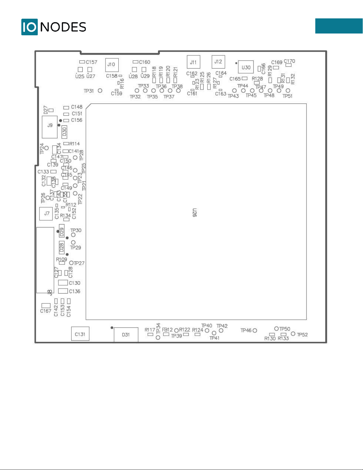
5.1 Board layout............................................................................................................................................ 7
5.2 Connector Part Numbers ....................................................................................................................... 9
5.2.1 J1 –Ethernet + Power .................................................................................................................... 10
5.2.2 J2 –MIPI Video Interface ............................................................................................................... 11
5.2.3 J3 –SD-CARD / SIM......................................................................................................................... 12
5.2.4 J4 –LVDS Video Interface .............................................................................................................. 13
5.2.5 J5 –Audio & I/O.............................................................................................................................. 14
5.2.1 J6 –Parallel Video Interface .......................................................................................................... 15
5.3 Understanding LED Status ................................................................................................................... 16
6ATOMAS-MINI-BOSON-ADAPT .................................................................................................................... 17
6.1 Board layout.......................................................................................................................................... 17
6.2 Connector Part Numbers ..................................................................................................................... 18
7ATOMAS-MINI-TENUM-ADAPT .................................................................................................................... 19
7.1 Board layout.......................................................................................................................................... 19
7.2 Connector Part Numbers ..................................................................................................................... 20
8ATOMAS-IOT-DUAL-SDSIM-ADAPT.............................................................................................................. 21
8.1 Board layout.......................................................................................................................................... 21
8.2 Connector Part Numbers ..................................................................................................................... 22
9ATOMAS-IOT-DUAL-HDCOMP-ADAPT......................................................................................................... 23
9.1 Board layout.......................................................................................................................................... 23
9.2 Connector Part Numbers ..................................................................................................................... 24
10 System Configuration............................................................................................................................... 25
10.1 Initial Network Configuration............................................................................................................... 25

4
www.ionodes.com
1About the ATOMAS-IOT-DUAL
The ATOMAS-IOT-DUAL dual port IP video encoder module delivers high quality H.265/H.264 video
encoding to be used within a variety of applications in a multitude of markets. It is an embedded, high-
performance IP video encoder module designed for integration into industry specific products looking to
add state of the art IoT video capabilities such as unmanned vehicles, drones, thermal camera systems and
many others.
Open Platform API
Embedding support for networked API’s such as ONVIF and the ION API, products based on the ATOMAS-
IOT-DUAL can be integrated into a networked video management system allowing for centralized
monitoring and management in a scalable and expandable IP surveillance system. Contact IONODES for
a list of supported VMS systems, on-premises and Cloud.
Simultaneous Dual Camera Support
The ATOMAS-IOT-DUAL is designed for direct connection to the leading LVDS zoom camera blocks, such as
SONY and KT&C, with simultaneous support of a MIPI and or digital video source such, such as a thermal
camera. Both cameras are processed simultaneously and published via ONVIF and other IP APIs for
streaming / recording.
High Performance Video Engine
The ATOMAS-IOT-DUAL features a powerful video codec engine capable of generating multiple HEVC /
H.264 IP video streams at different quality settings. In single input mode, it can generate streams at up to
4K30FPS; in dual input mode it can generate streams at up to 2K30FPS for each input.
IoT Enabled for Endless Possibilities
The ATOMAS-IOT-DUAL offers the latest in loT and networking connectivity functions including Ethernet,
4G LTE, Wi-Fi, GPS, Bluetooth, CAN Bus, 9-axis IMU and much more.

5
www.ionodes.com
2Parts List
Qty Description
1x ATOMAS-IOT-DUAL Module
Note: When unpacking, inspect the shipment box and appliance to identify any possible damages due
to shipping. Make sure all items have been delivered and that no items are missing. Contact your
IONODES representative should you find any damages or defects.
Note: The product serial number label helps our product support team identify your device and its
factory configuration in the event that your IONODES product or its components require service.
The label is attached to the underside of the PCBA.

6
www.ionodes.com
3Hardware Integration
The ATOMAS-IOT-DUAL has been designed to allow for flexible hardware integration to existing or new
product designs. The ATOMAS-IOT-DUAL proposes three (3) mounting holes for securing to your
enclosure. In addition, a slight clearance around the board’s edge can also be used for extrusion-type
enclosures.
When integrating the ATOMAS-IOT-DUAL into a product design, position the module to allow for air
circulation around the board in order to maximize the chances of heat dissipation.
Warning: Be careful not to damage the module when using mounting screws.
4Temperature Considerations
The ATOMAS-IOT-DUAL has been designed with extended temperature components (-20C to +70C);
however, reaching your temperature requirements may require that you add heatsinks to certain board-
level components which generate substantial heat (the main one being the SoC). The placement of the
SoC is clearly marked in the picture below.

7
www.ionodes.com
5ATOMAS-IOT-DUAL Specifications and Functions
5.1 Board layout
Figure 1 - ATOMAS-IOT-DUAL Top Side

8
www.ionodes.com
Figure 2 - ATOMAS-IOT-DUAL Bottom Side

9
www.ionodes.com
5.2 Connector Part Numbers
•ATOMAS-IOT-DUAL
oJ1 –Ethernet + Power / Molex 203564-2017
oJ2 –MIPI Video Interface / Hirose BM20B(0.8)-30DS-0.4V
oJ3 –SD-CARD / SIM / Molex 503480-1600
oJ4 –LVDS Video Interface / KEL Corporation USL00-30L-A
oJ5 –Audio & I/O / Molex 203564-3017
oJ6 –Parallel Video Interface / KEL Corporation USL00-30L-A
oJ7 –Cellular Main Antenna / Hirose U.FL-R-SMT-1
oJ10 –Cellular Diversity Antenna / Hirose U.FL-R-SMT-1
oJ11 –GNSS Antenna / Hirose U.FL-R-SMT-1
oJ12 –Wi-Fi/Bluetooth Antenna / Hirose U.FL-R-SMT-1

10
www.ionodes.com
5.2.1 J1 –Ethernet + Power
Molex 203564-2017
Pin No.
Name
Comments
1
VIN
9V to 15V, with 4A fuse protection
2
VIN
9V to 15V, with 4A fuse protection
3
VIN
9V to 15V, with 4A fuse protection
4
VIN
9V to 15V, with 4A fuse protection
5
3.3V OUT
max 100mA, combined with J5 pin 21
6
5V OUT
max 1A
7
GND
8
GND
9
Factory Default
10
GND
11
GND
12
Eth LED Yellow
Connects directly to RJ45 or network wiring
13
VRTC
DC Power Input for RTC (2.0V to 3.25V)
14
Eth LED Green
Connects directly to RJ45 or network wiring
15
NOT CONNECTED
16
NOT CONNECTED
17
ETH0 –
Connects directly to RJ45 or network wiring
18
ETH1 +
Connects directly to RJ45 or network wiring
19
ETH0 +
Connects directly to RJ45 or network wiring
20
ETH1 –
Connects directly to RJ45 or network wiring
VRTC is provided in order to allow for optional integration of an external battery source (2.0V to 3.25V) for
feeding the module’s real-time clock (RTC). VRTC is only required to keep the date/time when the main
power supply is not connected. All other data is saved in the persistent FLASH memory. The expected
consumption is around 0.0045 mA. Based on the desired holdup time, the system integrator should select
the appropriate battery capacity. We recommend using Seiko Instruments MS621FE-FL11E coin cell battery,
which is rated at 3V output and 5.5 mAh capacity.
J1 provides standard 4-wire network connectivity. You only need 4 wires for 10/100 Base-T
network connection; please connect the appropriate network connection pins to your RJ45
connector or wiring. Network status LED pins are also accessible if needed.

11
www.ionodes.com
5.2.2 J2 –MIPI Video Interface
Hirose BM20B(0.8)-30DS-0.4V
Pin No.
Name
Comments
1
MIPI-DATA1-
2
MIPI-DATA1+
3
DGND
4
MIPI-DATA3-
5
MIPI-DATA3+
6
DGND
7
MIPI-DATA0-
8
MIPI-DATA0+
9
DGND
10
MIPI-DATA2-
11
MIPI-DATA2+
12
DGND
13
MIPI-CLK-
14
MIPI-CLK+
15
AGND
16
NOT CONNECTED
17
AVDD
2.8V
18
DVDD
1.2V
19
DOVDD
1.8V
20
NOT CONNECTED
21
CLK
22
NOT CONNECTED
23
SID
0 (connected to GND)
24
I2C SCL
25
I2C SDA
26
#Reset
27
NOT CONNECTED
28
NOT CONNECTED
29
NOT CONNECTED
30
NOT CONNECTED
Note: This video interface is natively compatible with the IONODES MIPI camera with OV12A10 sensor
and Panomorph lens (ION-CAM-OV12A10MIPI). For connecting other MIPI cameras an adapter
board is required.

12
www.ionodes.com
5.2.3 J3 –SD-CARD / SIM
Molex 503480-1600
Pin No.
Name
Comments
1
SD DATA2
2
SD DATA3
3
SD CMD
4
SD VDD
5
SD CLK
6
GND
7
SD DATA0
8
SD DATA1
9
SD Detect
10
GND
11
GND
12
SIM VDD
13
SIM RST
14
SIM CLK
15
SIM Detect
16
SIM DATA
17
GND
18
GND
Note: This socket is intended to be connected to the optional IONODES SIM/SD combo adapter board.
In order to use the SD functionalities, make sure to install a microSD card of up to 512GB
capacity, with speed class 10 or above for optimal performance. You must also make sure the
card is formatted in EXT4 (formatting of the card can also be performed via the encoder).

13
www.ionodes.com
5.2.4 J4 –LVDS Video Interface
KEL Corporation USL00-30L-A
Pin No.
Name
Comments
1
LVDS DATA3 +
2
LVDS DATA3 -
3
LVDS CLK +
4
LVDS CLK -
5
LVDS DATA2 +
6
LVDS DATA2 -
7
LVDS DATA1 +
8
LVDS DATA1 -
9
LVDS DATA0 +
10
LVDS DATA0-
11
GND
12
CAM UART TX
Connects to the camera’s Rx
13
CAM UART RX
Connects to the camera’s Tx
14
DC IN
6V to 12V
15
DC IN
6V to 12V
16
DC IN
6V to 12V
17
DC IN
6V to 12V
18
DC IN
6V to 12V
19
GND
20
GND
21
LVDS DATA7 +
22
LVDS DATA7 -
23
LVDS DATA6 +
24
LVDS DATA6 +
25
NOT CONNECTED
26
Reset#
27
LVDS DATA5 +
28
LVDS DATA5 -
29
LVDS DATA4 +
30
LVDS DATA4 -

14
www.ionodes.com
5.2.5 J5 –Audio & I/O
Molex 203564-3017
Pin No.
Name
Comments
1
GPIO IN1
3.3V
2
I2C SCL
1.8V
3
GPIO IN2
3.3V
4
I2C SDA
1.8V
5
GPIO Out
3.3V
6
GND
7
GND
8
NOT CONNECTED
9
Audio Line IN Left
10
Audio Line OUT Left
11
GND
12
Audio Line OUT Right
13
Audio Line IN Right
14
Audio OUT Common
15
PWM3
3.3V
16
NOT CONNECTED
17
PWM2
3.3V
18
CAN –
19
PWM1
3.3V
20
CAN +
21
3V3 OUT
max 100mA, combined with J1 pin 5
22
GND
23
UART0 RS-422/485 TX –
24
UART0 RS-422/485 RX –
25
UART0 RS-422/485 TX +
26
UART0 RS-422/485 RX +
27
UART0 RX
TTL level, 3.3V
28
UART1 RX
TTL level, 3.3V
29
UART0 TX
TTL level, 3.3V
30
UART1 TX
TTL level, 3.3V
Note: The RS-422/485 and UART 0 are internally using the same port, so they cannot be used both at the
same time. The configuration is software selectable.

15
www.ionodes.com
5.2.1 J6 –Parallel Video Interface
KEL Corporation USL00-30L-A
Pin No.
Name
Comments
1
VIN
3.3V or 5V, software selectable
2
VIN
3.3V or 5V, software selectable
3
GND
4
DATA14
5
DATA8
6
DATA4
7
DATA7
8
#Reset
9
UART To Sensor
TTL level, 1.8V
10
DATA5
11
DATA6
12
DATA13
13
UART To CPU
TTL level, 1.8V
14
DATA15
15
DATA10
16
DATA12
17
Pixel Clock
18
DATA9
19
DATA11
20
DATA2
21
GND
22
VSYNC
23
DATA3
24
DATA1
25
I2C SCL
1.8V
26
I2C SDA
1.8V
27
HSYNC
28
DATA0
29
FSYNC / DATA_EN
30
GND
Note: In order to connect a camera block via this interface an adapter board is required. Currently, the
only available adapters are for the FLIR BOSON 320/640 (60 Hz version only), DRS Tenum 640
thermal cameras and analog HD component/ SD composite cameras.

16
www.ionodes.com
5.3 Understanding LED Status
Status of the ATOMAS-IOT-DUAL is exposed via the on-board bi-color LED (Green/Red).
The following describes the system status LED mappings of the ATOMAS-IOT-DUAL:
Normal Operation:
•Operating system boot up –LED is steady red (2-5 seconds) and after that LED is steady orange (30-
45 seconds)
•Internal application startup –LED is flashing orange (2 second interval)
•System ready –LED is steady green
•Media streaming –LED is flashing green (1/2 second interval)
Special Operations:
•Identify command received –LED is flashing orange/green
•Reset to factory settings –LED is flashing rapidly red/green
•Software watchdog is rebooting the appliance –LED is flashing rapidly red
•Firmware update in progress –LED is flashing slowly red/green

17
www.ionodes.com
6ATOMAS-MINI-BOSON-ADAPT
The ATOMAS-MINI-BOSON-ADAPT module is a video interface add-on module, fully compatible with the
ATOMAS-IOT-DUAL encoder platform. This optional module provides a direct connection to FLIR BOSON
320/640 (60Hz variant) thermal camera on the parallel video interface of the ATOMAS-IOT-DUAL.
6.1 Board layout
Figure 3 - ATOMAS-MINI-BOSON-ADAPT Top Side
Figure 4 - ATOMAS-MINI-BOSON-ADAPT Bottom Side

18
www.ionodes.com
6.2 Connector Part Numbers
•J1 –FLIR Connector / Hirose DF40HC-(4.0)-80DS-0.4V
•J2 –KEL Connector (towards ATOMAS-IOT-DUAL ) / KEL USL00-30L
Note: The J2 connector on the ATOMAS-MINI-BOSON-ADAPT module is designed to mate with connector
J6 of the ATOMAS-IOT-DUAL module.

19
www.ionodes.com
7ATOMAS-MINI-TENUM-ADAPT
The ATOMAS-MINI-TENUM-ADAPT module is a video interface add-on module, fully compatible with the
ATOMAS-IOT-DUAL encoder platform. This optional module provides a direct connection to DRS Tenum
640 thermal camera on the parallel video interface of the ATOMAS-IOT-DUAL.
7.1 Board layout
Figure 5 - ATOMAS-MINI-TENUM-ADAPT Top Side
Figure 6 - ATOMAS-MINI-TENUM-ADAPT Bottom Side

20
www.ionodes.com
7.2 Connector Part Numbers
•J1 –TENUM Connector / Samtec SS4-30-3.50-L-D-K-TR
•J2 –KEL Connector (towards ATOMAS-IOT-DUAL) / KEL USL00-30L
Note: The J2 connector on the ATOMAS-MINI-TENUM-ADAPT module is designed to mate with connector
J6 of the ATOMAS-IOT-DUAL.
•J3 –Power Connector / JST BM02B-ACHSS-GAN-ETF
Pin No.
Name
Comments
1
VIN
Requires +5V at 750mA
2
GND
Note: The J3 connector on the ATOMAS-MINI-TENUM-ADAPT module is designed to mate with a JST
ACHR-02V-S connector. It can be connected directly to the +5V output of the J1 connector of the
ATOMAS-IOT-DUAL.
Table of contents
Other IONODES Media Converter manuals

IONODES
IONODES ATOMAS-DUO-HDMI User manual

IONODES
IONODES ION-R100S User manual

IONODES
IONODES ATOMAS-MINI User manual

IONODES
IONODES ION-E100-HD User manual

IONODES
IONODES ION-R100S User manual

IONODES
IONODES ION-R100 User manual

IONODES
IONODES ION-R200 User manual

IONODES
IONODES ION-E100 User manual

IONODES
IONODES ION-R100S User manual
Popular Media Converter manuals by other brands

Puls
Puls QTD20.241 installation manual

EtherWAN
EtherWAN EL100 user manual

Delta Electronics
Delta Electronics PMC Series instruction manual

Bose
Bose SoundTouch Stereo JC series II quick start guide

Elettronica Santerno
Elettronica Santerno SINUS PENTA Applications manual

Linear Technology
Linear Technology LT1952-1 quick start guide