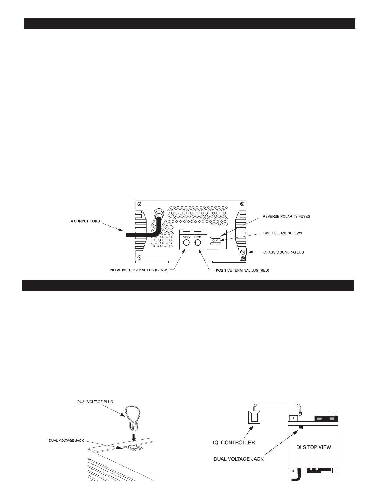
TWO-STEP VOLTAGE JACK
The two-step voltage jack (located on the top of the DLS on
thefan-endoftheunit)allowsswitchingfrom along-termfloat
voltage to an increased quick-charge voltage. When the in-
cluded dual voltage plug is inserted in the jack, the voltage
increases for faster charging. When the plug is removed, the
voltage drops to rated nominal voltage to reduce battery wa-
terloss.WARNING: To avoid battery damage, remove the
Dual Voltage Plug when quick-charging is complete.
There are no components within the DLS unit that, in their normal operation, produce arcs or sparks.
However, all electronic devices have some potential for generating sparks in the event of failure. Therefore,
never install this device in the same compartment with flammable items such as gasoline or batteries.
INSTALLATION GUIDELINES
MOUNTING LOCATION
The DLS battery charger/power supply can be mounted in
any position within an enclosed or interior compartment.
Provide sufficient air space to allow unrestricted airflow in
and around the unit.
DLS INSTALLATION
Disconnect the positive side of the battery before installation.
Connectthe positive(red)andnegative(black)terminallugs to
battery or load. Always use the proper size wire based on the
amperageoftheconverterandthebattery.Whenconnectingto
abattery,abreakershouldbeinstalledwithin18”ofthebattery,
connecting the battery positive to the line side of the breaker,
and the DLS to the load side. Connect “Chassis Bonding Lug”
on the DLS to vehicle chassis or other grounding source.
120 VOLT A.C. INPUT
Plug the DLS A.C. input cord into a 120 volt 3 wire
groundedsource.Seechartformaximumcurrentdraw
andrequiredinputvoltages.
REVERSE POLARITY FUSES
The DLS Battery Charger/Power Supply is protected
againstreverse polarityonthe DCoutput.Ifabattery or
the DLS is hooked up incorrectly, the fuses will blow
andcan be easily replaced. Always use the same size
andstylefuse thatcamewith theconverter.Tochange
the fuses, use a screwdriver to loosen the screws and
remove the fuses. Always replace the fuses with the
same type and rating. After inserting the new fuses,
tighten the screws firmly. DO NOT OVERTIGHTEN.
CHARGE CONTROLLER OPTIONS
IQ SMART CHARGER
DLS power converters/chargers are designed to accom-
modate the IQ smart charge controller. The microproces-
sor-controlledchargerturnstheDLScharger into an “auto-
matic” 3-stage “smart charger,” giving the user the benefit
of Bulk, Absorption, and Float stage charging. This in-
creases the charging capacity of the DLS charger, de-
creases charge times and insures proper and safe battery
charging without over-charging. The IQ controller inserts
into the dual voltage jack on the DLS.
ChargeController Optionsare designedforDLS unitsthat DONOT havethe IQSMART CONTROLFEATUREinternally
integrated.For units that feature an internal IQ controller, the Dual Voltage Jack is disabled.
68357-027
REV 102804


