manuals.online logo
Brands
  1. Home
  2. •
  3. Brands
  4. •
  5. IOTA
  6. •
  7. Batteries Charger
  8. •
  9. IOTA DLS-54V-13A User manual

IOTA DLS-54V-13A User manual

DLS
SERIES
POWER CONVERTERS & BATTERY CHARGERS FOR 48-VOLTS
OWNER’S MANUAL
Thank you for purchasing IOTA’s DLS Series Power Converter/Battery Charger. When utilized properly, your DLS Power
Converter/Battery Charger will provide years of dependable service. This Owner’s Manual contains important safety and
operating instructions. READ ALL INSTRUCTIONS AND SAFETY PRECAUTIONS CAREFULLY BEFORE INSTALLING
AND OPERATING THE UNIT.
WARNING
Risk of SERIOUS INJURY OR DEATH
This unit is an electrical device. When working with this, or any
electrical device, there exists the potential for
ELECTRICAL SHOCK, EXPLOSION and FIRE hazards.
Before using this equipment, READ AND UNDERSTAND the
instructions, warnings, and safety precautions in this Owner’s
Manual. Failure to read and understand these instructions could
result in SERIOUS INJURY or DEATH.
SAVE THESE INSTRUCTIONS
DANGER
ELECTRICAL SHOCK HAZARD
THIS CHARGER IS AN ELECTRICAL
DEVICE THAT CAN SHOCK AND CAUSE
SERIOUS INJURY.
DO NOT CUT POWER CORDS.
DO NOT SUBMERGE IN WATER OR GET
THE CHARGER WET.
EXPLOSION HAZARD
UNSUPERVISED, INCOMPATIBLE, OR
DAMAGED BATTERIES CAN EXPLODE
IF USED WITH A CHARGER.
DO NOT ATTEMPT TO CHARGE DAM-
AGED OR FROZEN BATTERIES.
USE THE CHARGER ONLY WITH BAT-
TERIES OF RECOMMENDED VOLTAGE.
OPERATE THE CHARGER IN
WELL-VENTILATED AREAS ONLY.
WARNING
FIRE HAZARD
A CHARGER IS AN ELECTRICAL DE-
VICE THAT EMITS HEAT AND CAN
BURN.
DO NOT COVER THE CHARGER.
KEEP THE CHARGER AWAY FROM
COMBUSTIBLE MATERIALS.
DO NOT SMOKE OR USE ANY
OTHER SOURCE OF ELECTRICAL
SPARK OR FIRE WHEN OPERATING
THE CHARGER.
CAUTION
When working with the DLS unit, always observe the
following guidelines:
• The DLS is designed for indoor use. Do not use outdoors.
• DO NOT expose the DLS unit to rain, snow, or other
inclement weather.
• Do not mount the DLS in a zero clearance compartment or
in compartments with ammable items such as gasoline or
batteries.
• Do not mount the DLS in an area with the potential of
dust, debris, or other foreign materials entering the vents
of the DLS.
• Use of an attachment or device with the DLS not recom-
mended by IOTA Engineering will void the warranty and
may result in a risk of re, electrical shock, or injury to
persons.
• To reduce the risk of damage to the electric plug and cord,
always pull by the plug and not the cord when disconnect-
ing the unit.
• DO NOT operate the DLS with a damaged cord or plug.
• DO NOT operate the DLS if it has been dropped, received
a sharp blow, or has been otherwise damaged in any way.
Take the DLS unit to a qualied service location.
• DO NOT disassemble the DLS unit. Take the DLS to
a qualied service location when service or repair is
required.
• To reduce the risk of electric shock, DISCONNECT the
DLS charger from ALL power sources before attempting
any maintenance or cleaning. Turning o󰀨 any electri-
cal supply or load to the unit is not su󰀩cient and will not
reduce this risk.
• DO NOT use extension cords. Using an improper
extension cord could result in a risk of fire and electric
shock, and may result in property damage, personal
injury or death.
RISK OF EXPLOSIVE GASES
WORKING IN THE VICINITY OF LEAD-
ACID BATTERIES IS DANGEROUS.
BATTERIES GENERATE EXPLOSIVE
GASES DURING NORMAL BATTERY
OPERATION. FOR THIS REASON, IT IS
OF UTMOST IMPORTANCE THAT YOU
FOLLOW THE INSTRUCTIONS WHEN
USING THE BATTERY CHARGER.
To reduce the risk of battery explosion, follow
these instructions and those published by the
battery manufacturer and review all Cautions
and Warnings associated with these products.
INSTALLATION GUIDELINES
MOUNTING LOCATION
The IOTA Power Converter/Battery Charger can be mounted
in any position within an enclosed or interior compartment.
Provide su󰀩cient air space to allow unrestricted airow in and
around the unit. Provide at least 4″around the fan of the DLS
to allow for proper air intake.
DO NOT mount the unit in a zero clearance compartment.
DO NOT mount the DLS in the same compartment with
ammable items such as gasoline or batteries. There are
no components within the DLS unit that, during normal
operation, produce arcs or sparks. However, all elec-
tronic devices have some potential for generating sparks
in the event of failure which can result in explosion or re.
DO NOT mount the DLS in an area that has the potential of dust,
debris, or other foreign materials to enter in through the DLS vents.
DO NOT place the DLS directly above the battery; the gases
from the battery can corrode and damage the DLS.
120 VOLT A.C. INPUT
Plug the unit A.C. input cord into an appropriate 120-volt 3-wire
grounded source. Refer to Illustration 2 for specications of the
cord provided with your DLS unit. See the Technical Specica-
tions Chart on page 4 for maximum current draw and required
input voltages.
DO NOT USE EXTENSION CORDS - Using an improper
extension cord could result in a risk of re and electric shock,
and may result in property damage, personal injury or death.
DO NOT OPERATE THE DLS WITH A DAMAGED CORD OR
PLUG. Have the cord or plug replaced immediately by qualied
service personnel.
To minimize the possibility of arcing at the battery, connect the
IOTApower cord to theAC input BEFORE connecting the battery.
Note: occasionally a small spark or arc may occur at the
power outlet as the unit is plugged in. This is a common
occurrence due to the internal capacitors drawing power.
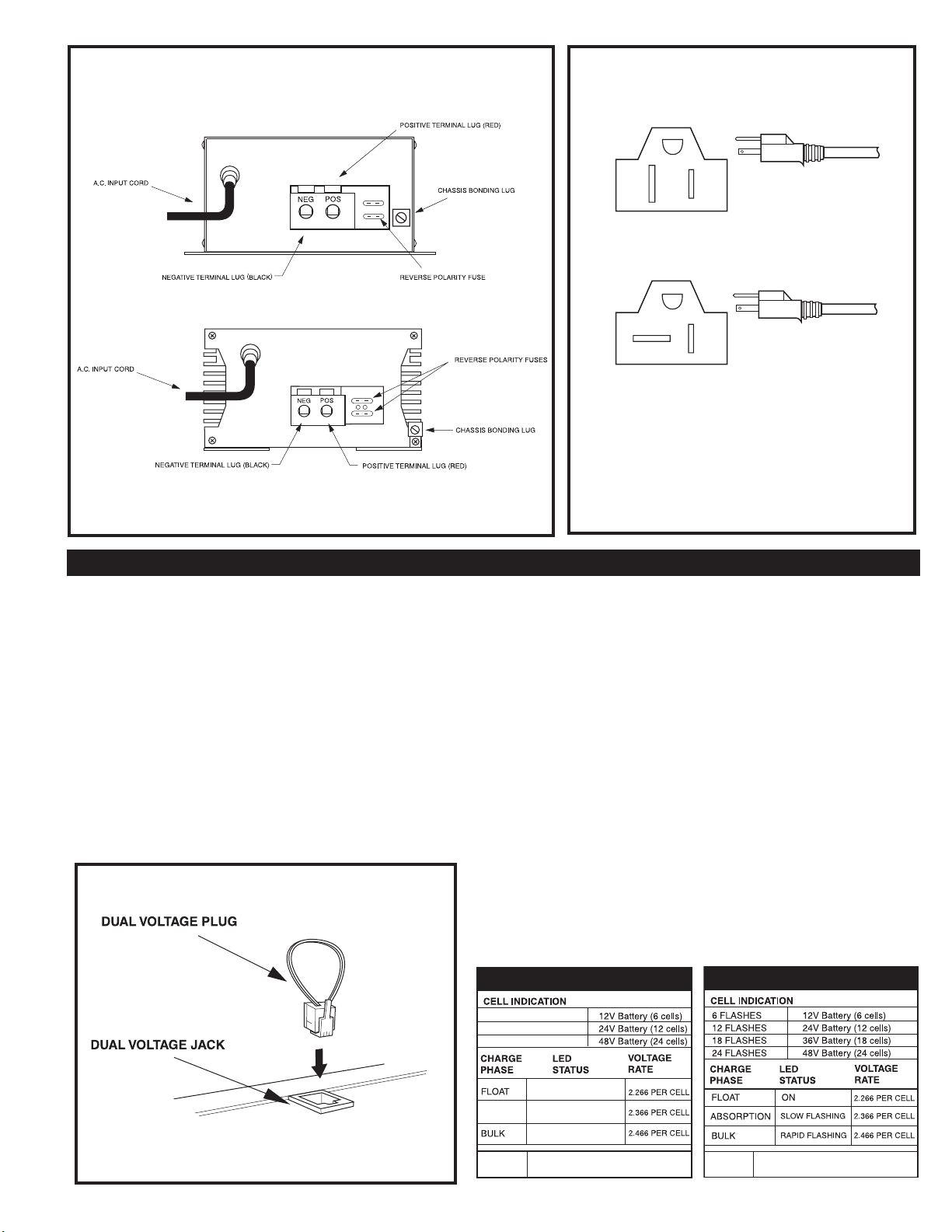
BATTERY CONNECTION
Disconnect the positive side of the battery before installation.
Connect the positive (red) and negative (black) terminal lugs to
battery or load (lugs require a #2 square drive). Always use the
proper size wire based on the amperage of the converter and
the battery. When connecting to a battery, a breaker should be
installed within 18″ of the battery, connecting the battery posi-
tive to the line side of the breaker, and the IOTA unit to the load
side. Connect “Chassis Bonding Lug” on the IOTA unit to vehicle
chassis or other grounding source. Refer to Illustration 1.
REVERSE POLARITY FUSES
The IOTA Battery Charger/Power Supply is protected against
reverse polarity on the DC output. If a battery or the unit is
hooked up incorrectly, the fuses will blow and can be easily
replaced. Always use the same size and style fuse that came
with the converter. To change the fuses, use a screwdriver
to loosen the screws and remove the fuses. Always replace
the fuses with the same type and rating. After inserting the
new fuses, tighten the screws rmly. Apply 5 inch-pound
maximum torque. DO NOT OVERTIGHTEN. Note: some DLS
models require only one fuse. For these units, a small berglass
spacer may be used in the empty fuse slot to aid with tightening.
IOTA DLS-48-20 Power Converter and DLS-54-13 Battery
Chargers convert 120 volts nominal A.C. to volts D.C. As a
power supply, the DLS-48-20’s tightly controlled regulation
allows the user to operate any 12 volt nominal D.C. load up
to the converter’s rated output current. As a battery char-
ger, the DLS-54-13 will maintain the battery, delivering its
full-rated current when the battery capacity falls su󰀩ciently
low. The voltage is set to deliver its maximum current for
the necessary period of time that minimizes undue stress
to the battery caused by heating of its cells. This helps to
ensure the longest possible life of the battery. Over time,
as the battery nears its full capacity, the converter will oat-
charge the battery to prevent self-discharge of its cells.
PROTECTION FEATURES
The IOTA Power Converters/Battery Chargers are
designed with high quality components to help ensure
years of continuous use. The unit is protected by multiple
protection features for a long, trouble-free life.
1) Reverse Battery Polarity Protection. 2) Brown-Out In-
put Protection. 3) Over-Current Protection - cycle by cycle
peak limiting as well as rated current limiting to maximize
the life of the converter. 4) Over-Temperature Protection.
In addition, it is designed with a unique “proportional” fan
control circuit. Fan speed is directly proportional to the
converter’s internal ambient temperature. This enables
the fan to turn on and o󰀨 very slowly, minimizing unwanted
fan-starting noise.
The IOTA Power Converters/Battery Chargers are war-
ranted from defects in materials or workmanship for two
years from date of retail purchase, and limits the remedies
to repair or replacement. This warranty is valid only in
the continental United States and Canada. For com-
plete warranty details, contact Customer Service or visit
www.iotaengineering.com.
WARRANTY
PRODUCT DESCRIPTION
TWO-STEP VOLTAGE JACK
The two-step voltage jack of the DLS-54-13 allows
switching from a long-term oat voltage of 54.4vdc to a
‘high-stage’ voltage of 56.8vdc. When the included dual
voltage plug is inserted in the jack*, the voltage rises to
56.8vdc for occasional fast charging. When the plug is
removed, the voltage drops to 54.4vdc to reduce battery
water loss. WARNING: To avoid battery damage, re-
move the Dual Voltage Plug when quick-charging is
complete. NOTE: If the unit is equipped with an internal
IQ4 smart charger, two-step charging is not needed and
the Dual Voltage Jack is disabled.
CHARGE CONTROL FOR THE DLS-54-13
DLS 54V 13A
*Actual component locations may vary depending on model.
Location of the Dual Voltage Jack may vary depending on model.
ILLUSTRATION 1 - DLS CONNECTIONS*
DLS 48V 20A
ILLUSTRATION 2 - AC INPUT PLUG
ILLUSTRATION 3 - DUAL VOLTAGE JACK
NEMA 5-20P PLUG
FOR 20A RECEPTACLE
NEMA 5-15P PLUG
FOR 15A RECEPTACLE
NEMA 5-15P PLUG
FOR 15A RECEPTACLE
DLS SERIES M
DLS 75A
DLS 90A
DLS 54V 13A
DLS 48V 20A
THE IQ4 LED INDICATOR
(ONLY ON IOTA MODELS WITH INTERNAL IQ4)
IOTA Models with an internal IQ4 smart-charger give the user the
benet of automatic Bulk, Absorption, and Float stage charging.
This increases the charging capacity of the IOTA charger, de-
creases charge times and insures proper and safe battery charg-
ing without over-charging. The LED on the fan end of the unit will
indicate which charging phase the IOTA unit is currently in. When
the unit is rst activated, the LED will ash as it reads the number
of cells in the battery. The unit will then proceed directly to the Bulk
charging or Float charging phase depending on the charge status
of the battery. Current DLS models utilize a three-color LED
while earlier models feature a single-color green LED. Refer-
ence the appropriate LED CODE TABLES below for the LED
codes pertaining to your particular unit. Units that do not have
an internal IQ4 smart-charger can easily install an external IQ4
that plugs into the available Dual Voltage Jack. Contact Customer
Service for more information.
FAULT SINGLE FLASH - INTERVAL > 1 SEC.
SINGLE-COLOR LED TABLE
6 FLASHES (GREEN)
12 FLASHES (GREEN)
24 FLASHES (GREEN)
ON (GREEN)
FLASHING (AMBER)SOAK
FLASHING (RED)
FAULT TRIPLE FLASH (RED) EVERY 2 SEC.
THREE-COLOR LED TABLE
Three-color LED Flashing code sequence
intervals are 0.5 SEC on / 0.5 SEC o󰀨.
Distributed By:
TECHNICAL SPECIFICATIONS CHART
68357-036 REV 2110
IOTA ENGINEERING PO BOX 11846 TUCSON, AZ 85734 TEL: 1-800-866-IOTA (4682) FAX: (520) 741-2837 WEB: www.iotaengineering.com
DC Output Voltage (No Load) approx.
Output Voltage Tolerance (No Load)
Output Amperage, Max Continuous
Output Voltage (Full Load) approx.
Maximum Power Output, Continuous
Ripple and Noise
Input Voltage Range
Input Voltage Frequency
Maximum AC Current (@108Vac)
Typical E󰀩ciency
Max Inrush Current, Single Cycle
Short Circuit Protection
Overload Protection
Line Regulation
Load Regulation
Fan Control
Thermal Protection
Working Temperature Range
Storage Temperature
Withstand Voltage (VDC)**
Approximate Dimensions
Weight
54.4V (DC)
+ or - .5%
13 Amps
>54V (DC)
700 Watts
<100 mV rms
108 - 132 AC
47-63
12.6 Amps
>80%
30 Amps
Yes
>100%
100 mV rms
<1%
PROPORTIONAL
YES
0° - 40° C
-20° to 80° C
1700/1700/500
9.7″ x 6.7″x 3.4″
5.0 lbs
48V (DC)
+ or - .5%
20Amps
>47.8V (DC)
950 Watts
<100 mV rms
108 - 132 AC
47-63
17.1 Amps
>80%
40 Amps
Yes
>100%
100 mV rms
<1%
PROPORTIONAL
YES
0° - 40° C
-20° to 80° C
1700/1700/500
13″ x 6.5″x 3.4″
7.8 lbs
DLS 54V 13A*DLS 48V 20A*
SERIES M
RATINGS AND SPECIFICATIONS
**Primary to Chassis/Primary to Secondary/Secondary to Chassis
*Unit is not UL Listed

This manual suits for next models

2

Other IOTA Batteries Charger manuals

IOTA DLS User manual

IOTA

IOTA DLS User manual

IOTA DLS SERIES User manual

IOTA

IOTA DLS SERIES User manual

IOTA DLS Series User manual

IOTA

IOTA DLS Series User manual

IOTA DLS-UI-27-40 User manual

IOTA

IOTA DLS-UI-27-40 User manual

IOTA DLS Series User manual

IOTA

IOTA DLS Series User manual

IOTA SDC1-120-12-30 User manual

IOTA

IOTA SDC1-120-12-30 User manual

IOTA DLS-15 User manual

IOTA

IOTA DLS-15 User manual

IOTA DLS-X Series User manual

IOTA

IOTA DLS-X Series User manual

IOTA DLS 27-15 User manual

IOTA

IOTA DLS 27-15 User manual

IOTA DLS-48-20 User manual

IOTA

IOTA DLS-48-20 User manual

IOTA DLS SERIES User manual

IOTA

IOTA DLS SERIES User manual

IOTA DLS-240-27-25 User manual

IOTA

IOTA DLS-240-27-25 User manual

IOTA DLS-15 User manual

IOTA

IOTA DLS-15 User manual

Popular Batteries Charger manuals by other brands

xtorm AM-116 manual

xtorm

xtorm AM-116 manual

Infinite Peripherals LINEA PRO 6 quick start guide

Infinite Peripherals

Infinite Peripherals LINEA PRO 6 quick start guide

Worcraft BC-217 manual

Worcraft

Worcraft BC-217 manual

GARO Wallbox GLB Series Assembly instructions / End User Instruction

GARO

GARO Wallbox GLB Series Assembly instructions / End User Instruction

Dynamite Prophet Select user manual

Dynamite

Dynamite Prophet Select user manual

Sealey SDC75 instructions

Sealey

Sealey SDC75 instructions

EcoFlow DELTA Pro user manual

EcoFlow

EcoFlow DELTA Pro user manual

Shell newmotion Home Advanced Edition 7 instruction manual

Shell

Shell newmotion Home Advanced Edition 7 instruction manual

Ozito PXBC-007U Original instructions

Ozito

Ozito PXBC-007U Original instructions

Hama Prima 2/4 operating instructions

Hama

Hama Prima 2/4 operating instructions

Scout SolarPlate user guide

Scout

Scout SolarPlate user guide

RANDOMORDER RO Fast Wireless Charger user guide

RANDOMORDER

RANDOMORDER RO Fast Wireless Charger user guide

X-Moove Smart 30 user guide

X-Moove

X-Moove Smart 30 user guide

Power Innovations EVQC0 M B Series Installation and operation manual

Power Innovations

Power Innovations EVQC0 M B Series Installation and operation manual

Osram BATTERYcharge PRO quick start guide

Osram

Osram BATTERYcharge PRO quick start guide

Kondo Kagaku DX201 Level user guide

Kondo Kagaku

Kondo Kagaku DX201 Level user guide

PowerBase C-733 user manual

PowerBase

PowerBase C-733 user manual

Tecknet U601 user manual

Tecknet

Tecknet U601 user manual

manuals.online logo
manuals.online logoBrands
  • About & Mission
  • Contact us
  • Privacy Policy
  • Terms and Conditions

Copyright 2025 Manuals.Online. All Rights Reserved.