manuals.online logo
Brands
  1. Home
  2. •
  3. Brands
  4. •
  5. IOTA
  6. •
  7. Safety Equipment
  8. •
  9. IOTA ETS20 Series User manual

IOTA ETS20 Series User manual

IMPORTANT SAFEGUARDS
When using electrical equipment, basic safety precautions should always be followed, including the following:
READ AND FOLLOW ALL SAFETY INSTRUCTIONS
1. CAUTION – This unit operates in conjunction with more than one power supply output source. To reduce the
risk of electrical shock, disconnect both normal and emergency sources by turning o󰀨 the A.C. branch circuit.
2. CAUTION – This is a sealed unit with no servicable parts. Replace the entire unit when necessary.
3. DO NOT USE OUTDOORS. The ETS20 is for use with grounded, UL Listed xtures. Not for use in heated air
outlets or hazardous locations.
4. The ETS20 requires an unswitched A.C. power source of either 120 to 277 volts, 50/60Hz.
5. Do not mount near gas or electric heaters.
6. The ETS20 should be mounted in locations and at heights where it will not readily be subjected to tampering
by unauthorized personnel.
7. The ETS20 is compatible with lighting xture loads on a 20 amp maximum circuit.
8. The use of accessory equipment not recommended by the manufacturer may cause an unsafe condition, void
warranty, and result in non-compliance with UL specications.
9. Do not use this equipment for other than intended use.
10. Mount only to an approved electrical enclosure.
11. Install in accordance with the National Electrical Code and local regulations.
12. Installation and servicing should be performed by qualied personnel.
13. Lighting xture manufacturers, electricians, and end-users need to ensure product system compatibility before
nal installation.
SAVE THESE INSTRUCTIONS
INSTRUCTION MANUAL
ETS20
SERIES HITEMP
20-AMP
EMERGENCY LIGHTING
CONTROL DEVICE
(800) 866-4682 • iotaengineering.com
Page 2
INSTALLATION INSTRUCTIONS
CAUTION: Before installing, make certain the A.C. power is o󰀨 on both normal
and emergency circuits.
1. Mounting the ETS20
The ETS20 is designed for connection to a junction box or electrical enclosure tted with a 7/8″diameter
(1/2″knockout). Remove the locking nut and insert the threaded nipple through the knockout. Tighten the
locking nut so that the unit is secured to the junction box or enclosure. See Illustration 1.
Illustration 1
2. Wiring
Refer to the wiring diagrams on Page 4 for the appropriate Normal Circuit and Emergency Circuit wiring
connections. Install in accordance with the National Electrical Code and local regulations.
3. Remote Device Installation (optional)
The ETS20 features an optional Remote Device lead for connection to a switch or other device to acti-
vate the unit and power the circuit from the emergency supply (such as a test switch or alarm system).
The Remote Device lead is a blue jumper loop that must be cut for connection to the remote device. Do
not cut this blue wire unless remote activation is desired.
NOTE: Perform Initial Testing (Section 4) before proceeding with Remote Device installation.
1) Cut the blue jumper lead.
2) Connect the two ends of the blue leads to the single pole contacts on the test switch or remote de-
vice (observe proper polarity of the blue wires and device connection, if necessary.) The device must
provide a normally closed, maintained, dry contact closure. The remote device must open the circuit in
order to force activation of the ETS20 into the Emergency Mode. If the device is a test switch, it must
be installed in an accessible location. Note: No more than (5) ETS20 units can be installed in paral-
lel with a remote device.
4. Initial Testing
After completing installation, verify that the ETS20 is functioning properly in both normal and emer-
gency operation. Testing should be conducted at a time and in a manner that does not a󰀨ect building
occupants and operations.
NOTE: Initial Testing should be performed with the blue jumper loop intact.
1) Turn on the circuit breaker in the emergency panel for the designated circuit. The Emergency Power
indicator (Red) should be lit. With only the emergency circuit on (Normal Power o󰀨), verify that all emer-
gency xtures are lit.
INSURE WIRING IS IN ACCORDANCE WITH THE NATIONAL ELECTRICAL CODE AND LOCAL REGULATIONS.
LOCKING NUT
JUNCTION BOX
ETS 20
Page 3
2) Temporarily disconnect and cap the wire connected to the Normal Switch Sense lead on the ETS20.
This will disable the normal control function and allow testing of the “fail-to-ON” function.
3) Turn on the circuit breaker in the normal panel of the designated circuit. The Normal Power (Green) in-
dicator will be lit indicating that normal power is present and that emergency lighting is not required. Emer-
gency lighting should be o󰀨. Conrm automatic Emergency On operation by turning o󰀨 the normal circuit
breaker. The emergency lighting should immediately turn on.
4) With the normal circuit breaker o󰀨, reconnect the wire to the Switch In lead. Turn on the normal circuit
breaker. The control device now controls both the normal and emergency lighting together.
Ready to Test Indicator
After installation of the remote switch or device (Section 3), the remote device should be in normal mode
(contacts closed) and the Ready to Test (Yellow) indicator on the ETS20 will be lit. When the remote device
is activated, or the remote test switch is pushed, the ETS20 bypasses the control device settings, allowing op-
eration of the emergency load. To conrm that the ETS20 is operating properly, set the wall switch or control
device in the ‘OFF’ position. Designated emergency xtures should come on when pressing the Test Button.
Note: for testing, the ETS20 will only bypass the control devices and operate the emergency xtures
from the normal supply - it does not activate nor conrm readiness of the auxiliary supply itself. The
Ready to Test (Yellow) indicator will extinguish and the Emergency Power (Red) indicator will remain lit.
If the Ready to Test Indicator is extinguished, it is an indication that Normal Power is lost or the unit is be-
ing forced into Emergency Power mode by the remote device or test switch. See Table A.
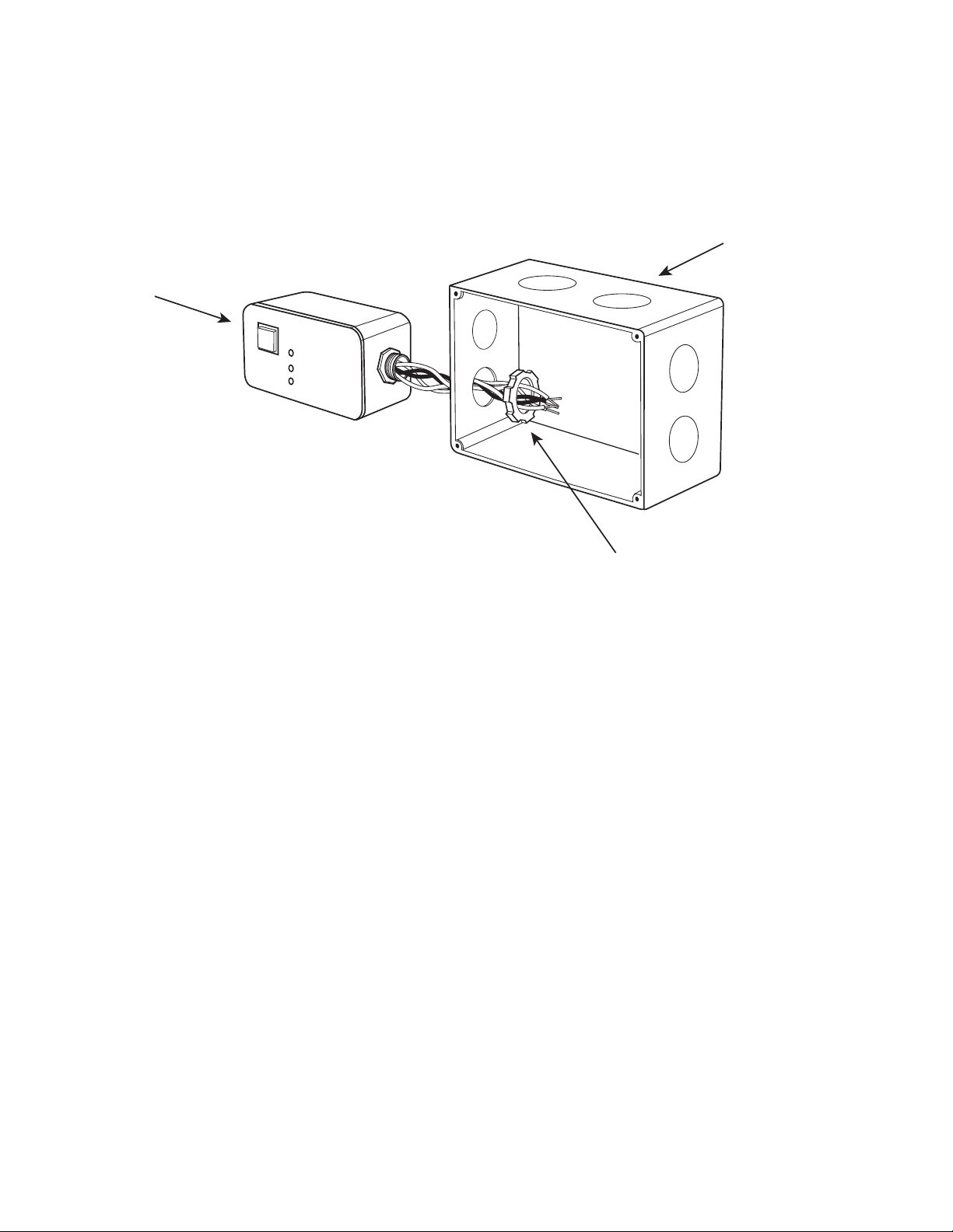
5. Labeling
A󰀩x a self-adhesive caution label in a visible location on the enclosure and on each xture controlled by
the ETS20 noting that the load is supplied from both normal and emergency power sources. Both power
sources must be disconnected before servicing the xture(s).
OPERATION
Normal Mode –A.C. power is present. Fixtures are operating normally and all indicators on the ETS20 will be
lit: Normal Power (Green), Emergency Power (Red), and Ready to Test (Yellow). See Table A.
Emergency Mode – The A.C. power fails. The ETS20 senses the A.C. power failure and automatically activates
the emergency load. All designated xtures are illuminated at full light output for as long as auxiliary power is avail-
able regardless of the normal wall switch position. The Emergency Power Indicator (Red) on the ETS20 is lit and
the Normal Power (Green) and Ready to Test (Yellow) indicators are o󰀨. When the A.C. power is restored, the
ETS20 switches the system back to the Normal Mode. See page 1 of the Instruction Manual.
TESTING & MAINTENANCE
The ETS20 is a maintenance free unit, however, periodic inspection and testing is required. Refer to the NFPA
101, Life Safety Code and local codes for required emergency testing schedules.
Testing should be conducted following maintenance or re-working of any of the xtures connected to the emer-
gency circuit.
“Written records of testing shall be kept by the owner for inspection by the authority having jurisdiction.”
SERVICING SHOULD BE PERFORMED BY QUALIFIED PERSONNEL.
Consult Customer Service or visit www.iotaengineering.com for current warranty information.
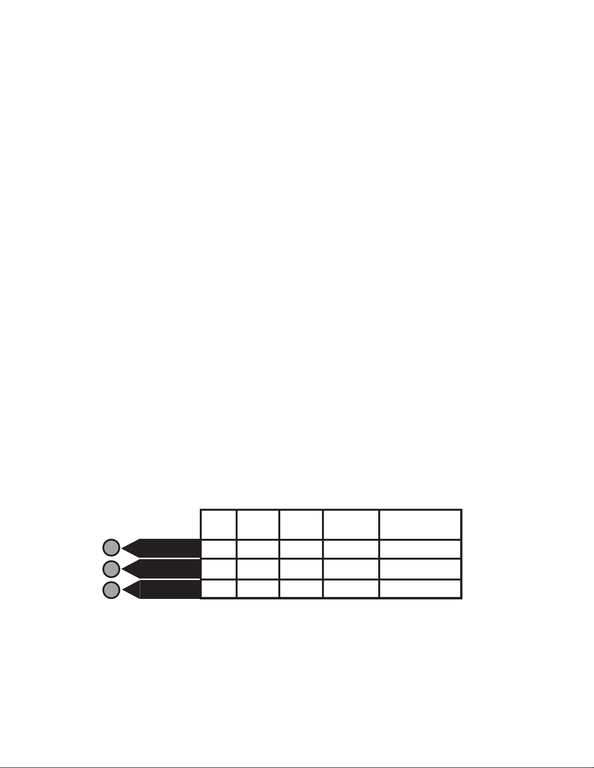
READY TO TEST
(YELLOW)
NORMAL POWER
(GREEN)
EMERGENCY POWER
(RED)
ON
ON
ON
STATUS
DESCRIPTION
--
--
ON
All OK
Normal
Power
not present
Emergency
Power
not present
--
ON
ON --
--
--
Normal and
Emergency Power
not present
Test Button is pressed or
Fire Alarm/Remote Device
is open
ON
ON
--
TABLE A: ETS20 INDICATOR DESCRIPTIONS
Page 4
TYPICAL WIRING DIAGRAMS
For additional wiring information, consult Customer Service.
Rev. 2200
68388-020
1. ETS20 STANDARD SWITCH WIRING
ETS-20 TYPICAL INSTALLATION
ETS_20_NEW
EMERGENCY CIRCUIT
BLK (12 AWG) - NORMAL/EM INPUT
NORMAL LINE
NORMAL NEUTRAL
EMERGENCY NEUTRAL
ETS20
NORMAL AND
EMERGENCY
LIGHTING LOAD
GRAY (18 AWG) - NORMAL/EM NEUTRAL
RED (12 AWG) - NORMAL/EM POWER OUTPUT
BLUE - REMOTE DEVICE JUMPER (OPTIONAL)
RED (18 AWG) - SWITCH SENSE
WHT (18 AWG) - NORMAL NEU
BLK (18 AWG) - NORMAL SENSE
NORMAL
LIGHTING LOAD
ONLY
CONTROL
DEVICE
CUT BLUE JUMPER
TO CONNECT WITH
REMOTE DEVICE
(OPTIONAL)
The RED and BLACK wires of the ETS 20 are distinguished by wire gauge.
Use the 12 AWG wires for connection to the emergency circuit.
The BLACK (Normal Sense) lead should be connected to the line side of the
Control Device that serves the same area as the emergency lighting, ensuring that
the emergency lighting in the controlled area turns on during a localized power failure.
NEUTRAL BUS
FOR NORMAL PANEL
NEUTRAL BUS
FOR EMERGENCY PA NEL
NORMAL
POWER
EMERGENCY
POWER
NORMAL
PANEL
EMERGENCY
PANEL
TRANSFER
SWITCH
N
G
Observe proper polarity, if necessary. No more than (5) ETS 20 units can be installed in parallel with a remote device.
ETS-20 WITH DIMMING CONTROL INSTALLATION
ETS_20_DR__NEW
EMERGENCY CIRCUIT
BLK (12 AWG) - NORMAL/EM INPUT
NORMAL LINE
NORMAL NEUTRAL
EMERGENCY NEUTRAL
ETS20
NORMAL AND
EMERGENCY
LIGHTING LOAD
GRAY (18 AWG) - NORMAL/EM NEUTRAL
RED (12 AWG) - NORMAL/EM OUTPUT
BLUE - REMOTE DEVICE JUMPER (OPTIONAL)
RED (18 AWG)
WHT (18 AWG) - NORMAL NEUTRAL
BLK (18 AWG) - NORMAL SENSE
NORMAL
LIGHTING LOAD
ONLY
DIMMER
CUT BLUE JUMPER
TO CONNECT WITH
REMOTE DEVICE
(OPTIONAL)
The RED and BLACK wires of the ETS 20 are distinguished by wire gauge. Use the 12 AWG wires for connection to the emergency circuit.
The BLACK (Normal Sense) lead should be connected to the line side of the
Control Device that serves the same area as the emergency lighting, ensuring that
the emergency lighting in the controlled area turns on during a localized power failure.
NEUTRAL BUS
FOR NORMAL PANEL
NEUTRAL BUS
FOR EMERGENCY PA NEL
NORMAL
POWER
EMERGENCY
POWER
NORMAL
PANEL
EMERGENCY
PANEL
TRANSFER
SWITCH
N
G
DIMMER
Cap unused lead.
Observe proper polarity, if necessary. No more than (5) ETS 20 units can be installed in parallel with a remote device.
2. ETS20 WIRING WITH DIMMER OPTION

Other IOTA Safety Equipment manuals

IOTA IIS Series User manual

IOTA

IOTA IIS Series User manual

IOTA B Series User manual

IOTA

IOTA B Series User manual

IOTA ETS20 DR Series User manual

IOTA

IOTA ETS20 DR Series User manual

Popular Safety Equipment manuals by other brands

Honeywell Miller H-Design DuraFlex manual

Honeywell

Honeywell Miller H-Design DuraFlex manual

ROTHOBLAAS SIANK4 installation manual

ROTHOBLAAS

ROTHOBLAAS SIANK4 installation manual

Climbing Technology UP ROLL manual

Climbing Technology

Climbing Technology UP ROLL manual

Petzl DELTA TECHNICAL NOTICE

Petzl

Petzl DELTA TECHNICAL NOTICE

Bornack STRIPE BASIC user manual

Bornack

Bornack STRIPE BASIC user manual

A.HABERKORN EDGER 6/12 INSTRUCTIONS FOR USE AND TEST MANUAL

A.HABERKORN

A.HABERKORN EDGER 6/12 INSTRUCTIONS FOR USE AND TEST MANUAL

MSA SingleLine SCOUT operating manual

MSA

MSA SingleLine SCOUT operating manual

GCE SAFE GUARD-2 Instructions for use

GCE

GCE SAFE GUARD-2 Instructions for use

Tractel travsafe PA Installation, operating and maintenance manual

Tractel

Tractel travsafe PA Installation, operating and maintenance manual

resqme alertme C200.701 instructions

resqme

resqme alertme C200.701 instructions

Petzl ALTITUDE/ TOUR manual

Petzl

Petzl ALTITUDE/ TOUR manual

Kentek KBH-5805 instructions

Kentek

Kentek KBH-5805 instructions

dynatec IN-6000 Instructions for use and maintenance

dynatec

dynatec IN-6000 Instructions for use and maintenance

Surewerx K1 Series User instructions

Surewerx

Surewerx K1 Series User instructions

Petzl BASIC B18 manual

Petzl

Petzl BASIC B18 manual

INFIELD E-MAN instruction manual

INFIELD

INFIELD E-MAN instruction manual

Acorn Safety S0730 Installation, operation and maintenance instructions

Acorn Safety

Acorn Safety S0730 Installation, operation and maintenance instructions

FHF HGW 11 User information

FHF

FHF HGW 11 User information

manuals.online logo
manuals.online logoBrands
  • About & Mission
  • Contact us
  • Privacy Policy
  • Terms and Conditions

Copyright 2025 Manuals.Online. All Rights Reserved.