manuals.online logo
Brands
  1. Home
  2. •
  3. Brands
  4. •
  5. IPAS
  6. •
  7. Control System
  8. •
  9. IPAS DaliControl e64 ProS Service manual

IPAS DaliControl e64 ProS Service manual

BMA_4101-145-03_e64ProS_en_Rev2 IPAS GmbH, Hölscherstraße 27, D-47167 Duisburg support@ipas-products.com
Operating and mounting instructions
DaliControl e64 ProS
Order No. 4101-145-03
General usage
The IPAS DALI Gateway DaliControl e64 ProS is a multi-master
application controller for controlling electronic ballasts with DALI
interface via the KNX installation bus. It supports ballasts according to
EN 62386-102 ed1 (DALI1), devices according to EN 62386-102 ed2
(DALI2), as well as DALI2 motion sensors and light sensors according
to EN 62386-303 and EN 62386-304.
The device transforms switching and dimming commands from the
connected KNX system into corresponding DALI telegrams, or status
and event information from the DALI bus into KNX telegrams.
The DaliControl e64 ProS has a DALI output which can control up to
64 ECGs. In addition, up to 8 DALI2 motion detectors or light sensors
can be connected. Multi-master operation according to EN 62386-103
ed2 is permitted. The required power supply for the connected ECGs
and motion sensors is provided directly from the device. Additional
DALI power sup-plies are not required. When using sensors supplied
via the DALI bus, it must be ensured that the current consumption of
all connected DALI devices does not exceed the guaranteed value.
The device is available in a 4 DU wide DIN rail housing for direct
installation in an electrical distribution board. The bus connection is
made via a standard bus connector. Mains and DALI lines are
connected via screw terminals on the device. Ethernet can be
connected via RJ45 sockets.It has an integrated switch to connect 2 IP
devices.
Per gateway the ECGs can be controlled in 16 groups. In addition to
the group control the DaliControl e64 ProS also allows individual
control of up to 64 ECGs.
In addition to the control of all standard operating devices, the
DaliControl e64 ProS also allows the operation of single battery
emergency lights (EN 62386-202). Emergency lighting systems with
central battery are also supported.
A maximum of 8 motion detectors with light sensors can also be
controlled.
The special interface for configuring the DALI segments is
designed as a DCA (Device Control App) for the ETS5. Please
make sure that the corresponding etsapp is installed in addition
to the product database knxprod. This is available for download
at Konnex or on the IPAS website.
Product features
•Addressing of 16 DALI groups and/or individual addressing of up
to 64 individual ECGs
•Flexible DALI commissioning concept: directly on the device, via
integrated web server or in the ETS5 (DCA)
•Coloured light control with the support of Device Type 8 (DT-8)
ballasts and control via communication objects
•Coloured light control depending on ballast Sub-Type:
- Colour Temperature (DT-8 Sub-Type Tc)
- XY Colour (DT-8 Sub-Type XY)
- RGB (DT-8 Sub-Type RGBWAF)
- HSV (DT-8 Sub-Type RGBWAF)
- RGBW (DT-8 Sub-Type RGBWAF)
•Automatic, time-controlled setting of light value, light colour and
colour temperature (also for Human Centric Lighting applications)
for groups and/or individual ECGs
•Automatic change of colour temperature depending on the light
value (Dimm-To-Cold)
•Control of colour temperature via communication object for DT6,
warm white and cool white
•Broadcast objects for controlling all connected ECGs
simultaneously (also possible for color values)
•Various operating modes for groups such as continuous mode,
night mode, staircase mode
•Integrated operating hours counter for each group and/or
individual ECG with alarm when end of life is reached
•Individual fault detection with objects for each individual
luminaire/EVG
•Complex error evaluation on group/device level with error number
and error rate calculation
•Error threshold monitoring with individually adjustable threshold
values
•Scene module for up to 16 scenes, which can be assigned to
KNX scenes 1..64 as required
•Extensive scene programming, including the possibility of
dimming scenes
•Setting of colour in DT-8 luminaires via scenes for groups and/or
individual ECGs
•Effect module for sequence controls and lighting effects including
colour adjustment in DT-8 luminaires
•Test mode for systems with emergency luminaires supplied by
central battery
•Support of single-battery emergency lights DT-1
•Support of test procedures for emergency lights with time and
date stamp
•"Quick Exchange Function" for easy replacement of individual
defective ECGs
•"Energy saving function" allows the ECG power supply to be
switched off when light is switched off via additional switching
actuators
•Integrated web server with extensive options for commissioning
and maintenance
•Integrated "Visualization" via Web browser for direct operation
and display
•Cross-device summary of errors in the entire system
•Manual operation of group and broadcast telegrams via operating
keys and display on the device
•Signalling of error states and status diagnosis via LEDs and
display on the device
Device types and accessories
At present the following DaliControl device types are available:
DaliControl gc16 Order no.: 4101-145-11
DaliControl gc16-2 Order no.: 4101-145-21
DaliControl e64 Order no.: 4101-145-01
DaliControl e64 Pro Order no: 4101-145-02
DaliControl e64 ProS Order no.: 4101-145-03
BMA_4101-145-03_e64ProS_en_Rev2 IPAS GmbH, Hölscherstraße 27, D-47167 Duisburg support@ipas-products.com
Scope of delivery
The following individual components are included in the delivery of the
DaliControl e64 ProS device:
•Complete device with connected bus connector
•1x heat shrinkable tubing 1.2 x 2cm for additional insulation of the
bus cable
•Operating and mounting instructions
•Delivered in break-proof individual packaging
Application programs
The following application programs are currently available for the
DaliControl e64 device:
DaliControl e64 Pro-01-0110
For application program functions, please see the application program
description.
Installation advices
Risk of death by electric shock
•The device is intended for interior installation in dry rooms.
•The device must only be installed and commissioned by an
accredited electrical engineer.
•Please follow country-specific safety and accident prevention rules
as well as all current KNX guidelines.
•Please follow country-specific rules and regulations for the planning
and construction of installations, especially with regard to
emergency lighting systems.
•For the installation, the device must be switched to zero potential.
•Do not open the device! Faulty devices must be returned to the
manufacturer with return delivery note.
Technical data
Power supply
•Operating voltage 100 to 240 V, 50 to 60Hz AC or DC
•Maximum power consumption 8 W
•Bus power supply via KNX bus line, SELV 24 V, ca. 5 mA
Connectors
•Mains connector L N PE: Screw connector 3x 1- 2.5 mm²
single or threaded core
•DALI-Bus D+, D- : Screw connector 2x 1-2.5 mm²
single or threaded core
•Bus line: Bus connector KNX, screwless
0.6…0.8 mm, single core
•Ethernet Eth 1, Eth. 2: RJ-45 plug connector for standard
patch cables
Control elements
•Programming button to toggle between normal and addressing
mode of the KNX
•3x buttons (Move, Prg/Set, ESC) for manual control and for
activation of broadcast and service functions
Display elements
•LED red: Indicates normal/addressing mode
•LNK-LED yellow: Signals device Ethernet readiness
•ERR-LED red: Signals fault status
•LC-Display, 2x12 characters: for configuration menu manual
operation and device adjustments
KNX-Bus
•KNX Medium: Twisted Pair (TP)
•Security: KNX Data Secure
DALI Bus
•Number of outputs: 1 DALI output
•Output type: Multi-Master Application Controller
according to EN 62386-103 ed 2
•Number of ballasts: max. 64 ECGs according to
EN 62386-101 ed1 and ed 2
•Number of sensors: max. 8 motion detectors and sensors
according to EN 62386-303 / -304
•DALI voltage: typic. 18 VDC, short-circuit proof max.
250 mA, basic insulation (no SELV)
•Recommended wire cross-section: min. 1.5 mm²
•Guaranteed
supply current: 160mA
•Maximum supply current: 250mA
•Shutdown delay: 600ms after DALI short circuit
shutdown occurs
•Start-up attempt
after shutdown: 5s after short-circuit detection
Ethernet
•Type: 100BaseT (100Mbit/s)
•IP address allocation: via DHCP service or fixed IP address
•Internal Switch Function to Connect 2 IP Connections
Mechanical data
•Casing
DaliControl e64 ProS: Plastic ABS –V0
•Dimensions
REG casing 4 DU: Width: 72 mm
Height: 58 mm
Length: 90 mm
•Weight 160 g
•Mounting: 35 mm DIN rail
Electrical safety
•Protection type
(according to EN 60529): IP20
•Protection class
(according to IEC 1140) I
•Overvoltage category: III
•Pollution class
(according to EN60664-1): 2
•KNX Bus: SELV DC 24 V
•DALI Bus: typical18 V DC,
250 mA base isolation, (no SELV)
EMC requirements
Complies with directive 2014 / 30 / EU
Environmental conditions
•Environmental conditions
during operation: -5°C to +45°C
•Storage temperature: -25°C to +55°C
•Transportation
temperature: -25°C to +70°C
•Rel. humidity
(non condensing): 5 % to 93 %
Certification
•KNX certified
•DIIA certified according to EN 62386-101 ed 2 and
EN 62386-103 ed 2
CE-signage
According to EMC guidelines (residential and commercial buildings),
low voltage guidelines
Location and function of display and control elements
The device connections, as well as the elements learn button and
programming LED required for KNX commissioning are only
accessible in the distribution board when the cover is removed. The
buttons required for DALI commissioning and parameterisation
(MOVE, Prg/Set, ESC), as well as reading the 2-line display and the
control LEDs (ERR and LNK) can be operated with the distribution
board cover closed.
BMA_4101-145-03_e64ProS_en_Rev2 IPAS GmbH, Hölscherstraße 27, D-47167 Duisburg support@ipas-products.com
You must always follow the pin assignment as labelled on the
casing!
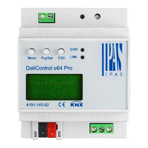
A1: 2x RJ-45 plug for Ethernet connection integrated Switch
A2: KNX bus connector
A3: Power supply connector
A4: DALI output connector
A5: Programming LED for normal/addressing mode
A6: Programming button normal/addressing mode
A7: MOVE button
A8: Prg/Set button
A9 ESC button
A10: Error-LED
A11: Ethernet-LNK-LED
A12: Display 2x12 characters for DALI configuration
Mounting and wiring
DaliControl e64 ProS is suitable for mounting in distribution boxes on
35 mm DIN rails. To mount the device it must be angled to slide onto
the DIN rail from above and then locked into place with a downward
movement. Please make sure that the security latch at the bottom side
of the device snaps into place and that the device is firmly attached to
the rail.
To dismount the device, the security latch can be pulled downwards
with a suitable tool and then the device can be removed from the rail.
After the device has been inserted, the cable for the DALI bus should
be attached to the upper left connector first. In accordance with EN
62386, the DALI control lines can be carried in a 5-wired cable
together with the power supply (simple basic insulation is sufficient).
However, please make sure that these are labelled clearly. For the
entire DALI installation of a segment, a maximum cable length of
300 m must not be exceeded. (Recommended cross-sectional area
1.5 mm²).
The power supply is connected to the top left-hand side connector in
the order indicated on the casing.
To connect the KNX cable, a standard bus connector is plugged into
the respective entry on the device.
Attention: Please make sure that there is double basic insulation
between the KNX installation and the power supply. To do so,
please insulate the wires of the KNX cable up to the bus
connector with the enclosed shrinkable tubing.
After complete connection and switching on the supply voltage, the
DALI segment can now be commissioned and programmed with the
ETS5, including the necessary etsapp. Please refer to the application
program description for carrying out these further procedures.

This manual suits for next models

1

Other IPAS Control System manuals

IPAS Axesso System User guide

IPAS

IPAS Axesso System User guide

IPAS PowerBlock o8 Service manual

IPAS

IPAS PowerBlock o8 Service manual

IPAS DALI Series Service manual

IPAS

IPAS DALI Series Service manual

IPAS DALI Series Service manual

IPAS

IPAS DALI Series Service manual

Popular Control System manuals by other brands

Lippert Components Sway Command Install manual

Lippert Components

Lippert Components Sway Command Install manual

Valeo SC600 Indien operating instructions

Valeo

Valeo SC600 Indien operating instructions

Volvo Penta Electronic Control System installation instructions

Volvo Penta

Volvo Penta Electronic Control System installation instructions

Tecnoalarm TP8-64 BUS Installer manual

Tecnoalarm

Tecnoalarm TP8-64 BUS Installer manual

Aybey Elektronik SWLINE Series user manual

Aybey Elektronik

Aybey Elektronik SWLINE Series user manual

Festo Checkbox Compact CHB-C-X manual

Festo

Festo Checkbox Compact CHB-C-X manual

Norac UC5 Topcon X30 installation manual

Norac

Norac UC5 Topcon X30 installation manual

ZIEHL-ABEGG ZETADYN 1DV Series System description

ZIEHL-ABEGG

ZIEHL-ABEGG ZETADYN 1DV Series System description

Melink Intelli-Hood installation manual

Melink

Melink Intelli-Hood installation manual

Weil-McLain BMC Install and operation instructions

Weil-McLain

Weil-McLain BMC Install and operation instructions

Siemens SIMATIC PCS 7 Function manual

Siemens

Siemens SIMATIC PCS 7 Function manual

Wintriss SmartPAC 2 user manual

Wintriss

Wintriss SmartPAC 2 user manual

Key Digital KD-X1000ProK operating instructions

Key Digital

Key Digital KD-X1000ProK operating instructions

Nxg VMS100 user guide

Nxg

Nxg VMS100 user guide

Compool Cp3810 Installation & operating instructions

Compool

Compool Cp3810 Installation & operating instructions

ADTRAN Total Access 300 Series Installation and maintenance guide

ADTRAN

ADTRAN Total Access 300 Series Installation and maintenance guide

Invacare Linx REM500 user manual

Invacare

Invacare Linx REM500 user manual

Siemens SIMATIC PC BI45 Technical description

Siemens

Siemens SIMATIC PC BI45 Technical description

manuals.online logo
manuals.online logoBrands
  • About & Mission
  • Contact us
  • Privacy Policy
  • Terms and Conditions

Copyright 2025 Manuals.Online. All Rights Reserved.