IPAS DALI Series Service manual

BMA_4101-145-11_gc16_en_Rev2 IPAS GmbH, Hölscherstraße 27, D-47167 Duisburg support@ipas-products.com
Operating and mounting instructions
DaliControl gc16
Order No. 4101-145-11
General usage
The IPAS DALI Gateway DaliControl gc16 is a device used to control
electronic control gears (ECGs) with a DALI interface (in accordance
with EN 62386) via the KNX installation bus. The device transforms
switch and dim commands from the connected KNX system into DALI
telegrams and status information from the DALI bus into KNX
telegrams.
The DaliControl gc16 is a so-called Single Master Application
Controller (according to EN 62386-103). This means the device must
only be used in DALI segments with connected ECGs and not with
other DALI control devices within the segment (no multi-master
operation). The required power supply for the up to 64 connected
ECGs comes directly from the DaliControl gc16. An additional DALI
power supply is not required and not permitted. Supported are ECGs
according to EN 62386-102 ed1 (DALI1) as well as devices according
to EN 62386-102 ed2 (DALI2).
With firmware version 0.2.5 or higher the DaliControl gc16 is
certified according to EN 62386-101 and -103 ed2 (DALI2) and
therefore entitled to bear the DALI-2 logo.
The device comes in a 4TE wide DIN Rail casing so it can be directly
integrated into the mains distribution box.
In addition to the pure gateway function, the DaliControl gc16 also
offers numerous additional functions
•Addressing of up to 16 DALI groups
•Flexible DALI commissioning concept in the ETS5
•Coloured light control with the help of device type 8 ECGs
•Coloured light control depending on ECG sub-type:
➢Colour temperature(DT-8 Sub-Type Tc)
➢XY colour (DT-8 Sub-Type XY)
➢RGB (DT-8 Sub-Type RGBWAF)
➢HSV (DT-8 Sub-Type RGBWAF)
➢RGBW (DT-8 Sub-Type RGBWAF)
➢The DT-8 sub-type PrimaryN is not supported.
•Support of time scheduling programmes to control groups
according to values and/or colour.
•Different operating modes such as permanent mode, night-time
mode or staircase mode
•Integrated operating hours counter for each group with an alarm
for when the maximum life-span has been reached
•Individual fault recognition with objects for each light/ECG
•Complex fault analysis at group/device level with number of faults
and fault rate calculation
•Fault threshold monitoring with individually configurable threshold
values
•Scene module for extensive scene programming
•“Quick exchange function“ for easy replacement of individual
faulty ECGs
•Manual control of group and broadcast telegrams via control
buttons on the device (see application program description for
operating instructions)
•Signaling of a fault status via LEDs on the device (see application
program description)
DALI devices for individual battery emergency lights of device type DT-
1 can be read by DaliControl gc16 and switched and controlled via
DALI telegrams. However, DALI commands to start and export test
results are not supported. We recommend using the DaliControl e64
for DT-1 devices.
The special surface for the configuration of DALI segments is designed
as DCA (Device Control App) for the ETS5.
Please remember to install the corresponding etsapp in addition to the
product database knxprod. The etsapp is available for download on the
IPAS website or from Konnex.
Device types and accessories
At present the following DaliControl device types are available:
DaliControl gc16 Best.Nr.: 4101-145-11
DaliControl gc16-2 Best.Nr.: 4101-145-21
DaliControl e64 Best.Nr.: 4101-145-01
Scope of delivery
The following individual components are included in the delivery of the
DaliControl gc16 device:
•Complete device with connected bus connector
•1x heat shrinkable tubing 1.2 x 2cm for additional insulation of the
bus cable
•Operating and mounting instructions
•Delivered in break-proof individual packaging
Application programs
At present the following application programs are available for the
DaliControl gc16 device:
DaliControl gc16-01-0110
Installation advices
Risk of death by electric shock
•The device is intended for interior installation in dry rooms.
•The devicemust only be installed and commissioned by anaccredited
electrical engineer.
•Please followcountry-specific safety and accident prevention rules as
well as all current KNX guidelines.
•Please follow country-specific rules and regulations for the planning
and construction of installations, especially with regard to emergency
lighting systems.
•For the installation, the device must be switched to zero potential.
•Do not open the device! Faulty devices must be returned to the
manufacturer with return delivery note.
Technical data
Power supply
•Operating voltage 110 to 240 V, 50 to 60Hz AC or DC
•Maximum power consumption 9W
•Bus power supply via KNX bus line, SELV 24V, ca. 5mA
Connectors
•Mains connector L N PE: Screw connector 3x 1- 2.5mm²
single or threaded core
•DALI-Bus D+, D- : Screw connector 2x 1-2.5 mm²
single or threaded core
•Bus line: Bus connector KNX, screwless
0.6…0.8mm, single core

BMA_4101-145-11_gc16_en_Rev2 IPAS GmbH, Hölscherstraße 27, D-47167 Duisburg support@ipas-products.com
Control elements
•Programming button to toggle between normal and addressing
mode of the KNX
•1 x button Man. to activate manual mode
•8x buttons to toggle between groups in manual mode and to
execute broadcast and service functions
Display elements
•LED red: Indicates normal/addressing mode
•LED red/green/blue: Indicates manual mode and error
message
•8x LED red: Indicates group status and error
messages
DALI-Bus
•Number of outputs: 1 DALI output
•Output type: Single-Master Application
Controller according to EN 62386-103 ed 2
•Number of ballasts: max. 64 ECGs according to
EN 62386-101 ed1 and ed 2
•DALI voltage: typically 16 VDC, short-circuit
proof max. 250mA, basic insulation (no SELV)
•Recommended wire cross-section: min. 1.5 mm²
•Guaranteed supply current: 128mA
•Maximum supply current: 250mA
•Shutdown delay: 600ms after DALI short circuit
shutdown occurs
•Start-up attempt after shutdown: 5s after short-circuit detection
Mechanical data
•DaliControl gc16 casing: Plastic ABS –V0
•Dimensions REG casing 4TE: 71mm x 58mm x 90mm (WxHxL)
•Weight: ca. 130 g
•Mounting: 35mm DIN rail
Electrical safety
•Protection type (in accordance with EN 60529): IP20
•Protection class (according to IEC 1140) I
•Overvoltage category: III
•Pollution class (in accordance with EN60664-1): 2
•KNX Bus: SELV DC 24 V
•DALI Bus: typical16V DC,
250mA base isolation, (no SELV)
EMC requirements
Complies with directive 2014 / 30 / EU
Environmental conditions
•Weather resistance: EN 50090-2-2,
•Environmental conditions during operation: -5°C to +45°C
•Storage temperature: -25°C to +55°C
•Transportation temperature: -25°C to +70°C
•Rel. humidity (non condensing): 5 % to 93 %
Certification
•KNX certified
•DIIA certified according to EN 62386-101 ed 2 and EN 62386-103
ed 2
CE-signage
According to EMC guidelines (residential and commercial buildings),
low voltage guidelines
Location and function of display and control elements
The device connectors as well as the programming button and
programming LED that are required for KNX commissioning, are only
accessible in the distribution box when the cover is removed.
The buttons required to activate manual control and to operate groups
and commands as well as the status and control LEDs are accessible
when the cover is closed.
You must always follow the pin assignment as labelled on the
casing!
A1: Mains connection
A2: DALI output
A3: KNX bus connector
A4: Programming LED to display normal/addressing mode
A5: Programming button normal/addressing mode
A6: Operating button/signal LED RGB manual mode
A7: 8x operating button/signal LED red group control/status,
broadcast and service functions
Mounting and wiring
As a REG device the DaliControl gc16 is suitable for mounting in
distribution boxes on 35 mm DIN rails. To mount the device it must be
angled to slide onto the DIN rail from above and then locked into place
with a downward movement. Please make sure that the security latch at
the bottom side of the device snaps into place and that the device is
firmly attached to the rail.
To dismount the device, the security latch can be pulled downwards with
a suitable tool and then the device can be removed from the rail.
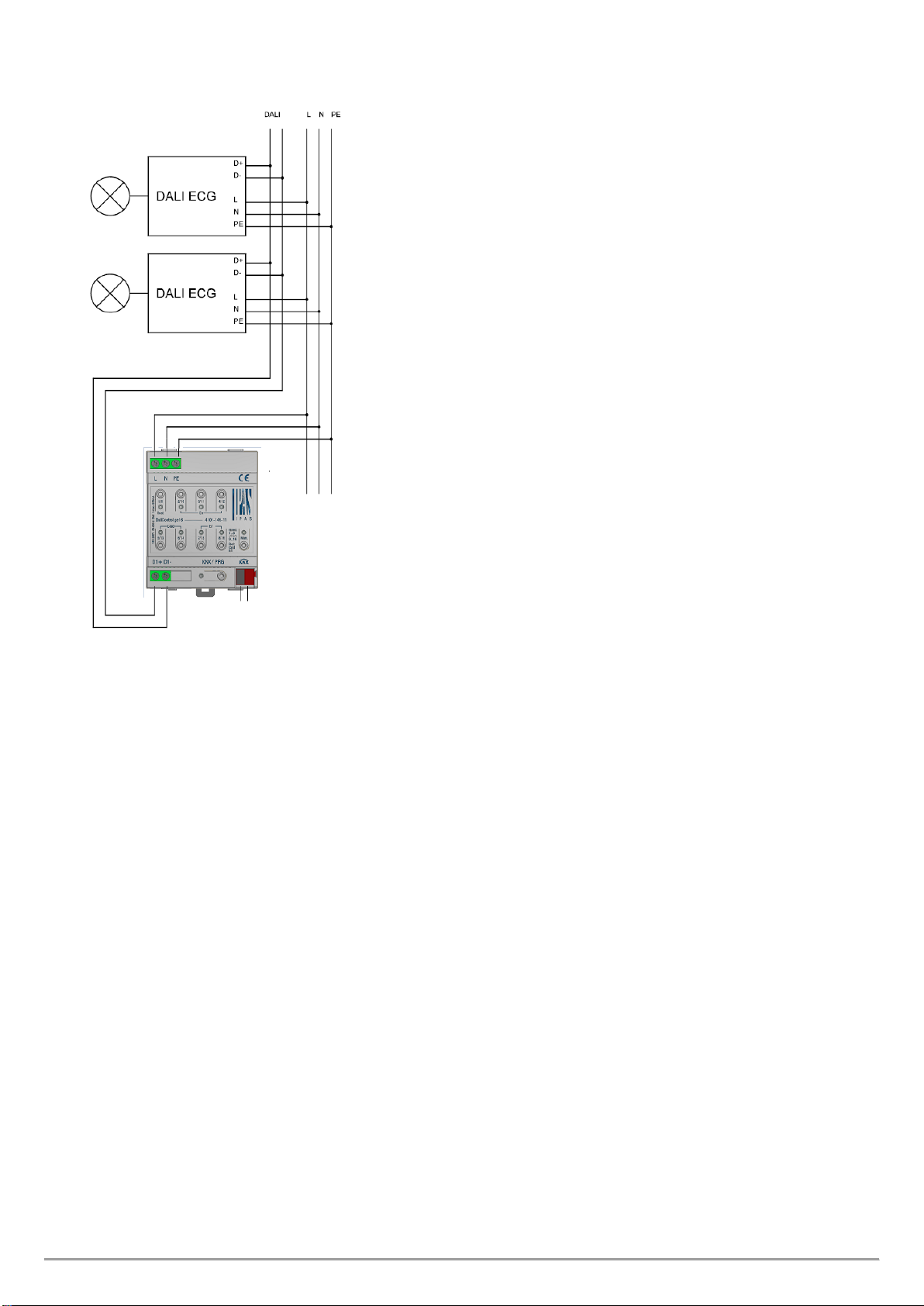
After the device has been inserted, the cable for the DALI bus should
be attached to the upper left connector first. In accordance with EN
62386, the DALI control lines can be carried in a 5-wired cable together
with the power supply (simple basic insulation is sufficient). However,
please make sure that these are labelled clearly. For the entire DALI
installation of a segment, a maximum cable length of 300m must not be
exceeded. (Recommended cross-sectional area 1.5mm²).
The power supply isconnected to the top left-hand side connector in the
order indicated on the casing.
To connect the KNX cable, a standard bus connector is plugged into the
respective entry on the device.
Attention: Please make sure that there is double basic insulation
between the KNX installation and the power supply. To do so,
please insulate the wires of the KNX cable up to the bus connector
with the enclosed shrinkable tubing.

BMA_4101-145-11_gc16_en_Rev2 IPAS GmbH, Hölscherstraße 27, D-47167 Duisburg support@ipas-products.com
Once the connection is complete and the power supply is turned on,
you can start commissioning the DALI segment and programming with
ETS. For all further processes, please see the application program
description.
This manual suits for next models
6
Other IPAS Control System manuals
Popular Control System manuals by other brands

Klimor
Klimor MCKT Operation and maintenance manual

Lamtec
Lamtec VMS Series manual

Kessler
Kessler AT-AUTO operating manual

YSI
YSI 5200A user manual

Jackson Systems
Jackson Systems Z-600 Installation and operation manual

Kemper
Kemper KHS Mini Control System MASTER 2.0 Installation and operating instructions