BMA_4101-145-02_e64Pro_en_Rev2 IPAS GmbH, Hölscherstraße 27, D-47167 Duisburg support@ipas-products.com
Operating and mounting instructions
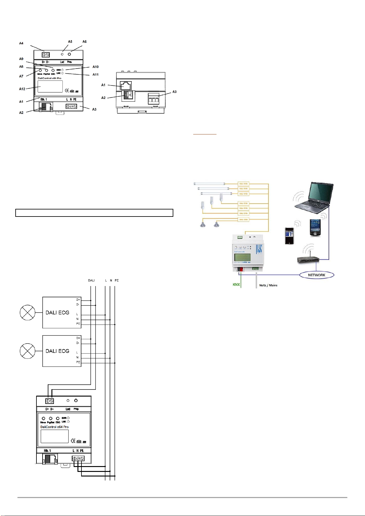
DaliControl e64 Pro
Order No. 4101-145-02
General usage
The IPAS DALI Gateway DaliControl e64 Pro is a multi-master
application controller for controlling electronic ballasts with DALI
interface via the KNX installation bus. It supports ballasts according to
EN 62386-102 ed1 (DALI1), devices according to EN 62386-102 ed2
(DALI2), as well as DALI2 motion sensors and light sensors according
to EN 62386-303 and EN 62386-304.
The device transforms switching and dimming commands from the
connected KNX system into corresponding DALI telegrams, or status
and event information from the DALI bus into KNX telegrams.
The DaliControl e64 Pro has a DALI output which can control up to 64
ECGs. In addition, up to 8 DALI2 motion detectors or light sensors can
be connected. Multi-master operation according to EN 62386-103 ed2
is permitted. The required power supply for the connected ECGs and
motion sensors is provided directly from the device. Additional DALI
power sup-plies are not required. When using sensors supplied via the
DALI bus, it must be ensured that the current consumption of all
connected DALI devices does not exceed the guaranteed value.
The device is available in a 4TE wide DIN rail housing for direct
installation in an electrical distribution board. The bus connection is
made via a standard bus connector. Mains and DALI lines are
connected via screw terminals on the de-vice. Ethernet is connected
via an RJ45 socket.
Per gateway the ECGs can be controlled in 16 groups. In addition to
the group control the DaliControl e64 Pro also allows individual control
of up to 64 ECGs.
In addition to the control of all standard operating devices, the
DaliControl e64 Pro also allows the operation of single battery
emergency lights (EN 62386-202). Emergency lighting systems with
central battery are also supported.
A maximum of 8 motion detectors with light sensors can also be
controlled.
The special interface for configuring the DALI segments is
designed as a DCA (Device Control App) for the ETS5. Please
make sure that the corresponding etsapp is installed in addition
to the product database knxprod. This is available for download
at Konnex or on the IPAS website.
Product features
•Addressing of 16 DALI groups and/or individual addressing of up
to 64 individual ECGs
•Flexible DALI commissioning concept: directly on the device, via
integrated web server or in the ETS5 (DCA)
•Coloured light control with the support of Device Type 8 (DT-8)
ballasts and control via communication objects
•Coloured light control depending on ballast Sub-Type:
- Colour Temperature (DT-8 Sub-Type Tc)
- XY Colour (DT-8 Sub-Type XY)
- RGB (DT-8 Sub-Type RGBWAF)
- HSV (DT-8 Sub-Type RGBWAF)
- RGBW (DT-8 Sub-Type RGBWAF)
•Automatic, time-controlled setting of light value, light colour and
colour temperature (also for Human Centric Lighting applications)
for groups and/or individual ECGs
•Automatic change of colour temperature depending on the light
value (Dimm-To-Cold)
•Control of colour temperature via communication object for DT6,
warm white and cool white
•Broadcast objects for controlling all connected ECGs
simultaneously (also possible for colour values)
•Various operating modes for groups such as continuous mode,
night mode, staircase mode
•Integrated operating hours counter for each group and/or
individual ECG with alarm when end of life is reached
•Individual fault detection with objects for each individual
luminaire/EVG
•Complex error evaluation on group/device level with error number
and error rate calculation
•Error threshold monitoring with individually adjustable threshold
values
•Scene module for up to 16 scenes, which can be assigned to
KNX scenes 1..64 as required
•Extensive scene programming, including the possibility of
dimming scenes
•Setting of colour in DT-8 luminaires via scenes for groups and/or
individual ECGs
•Effect module for sequence controls and lighting effects including
colour adjustment in DT-8 luminaires
•Test mode for systems with emergency luminaires supplied by
central battery
•Support of single-battery emergency lights DT-1
•Support of test procedures for emergency lights with time and
date stamp
•"Quick Exchange Function" for easy replacement of individual
defective ECGs
•"Energy saving function" allows the ECG power supply to be
switched off when light is switched off via additional switching
actuators
•Integrated web server with extensive options for commissioning
and maintenance
•Integrated "Visualization" via Web browser for direct operation
and display
•Cross-device summary of errors in the entire system
•Manual operation of group and broadcast telegrams via operating
keys and display on the device
•Signalling of error states and status diagnosis via LEDs and
display on the device
Device types and accessories
At present the following DaliControl device types are available:
DaliControl gc16 Best.Nr.: 4101-145-11
DaliControl gc16-2 Best.Nr.: 4101-145-21
DaliControl e64 Best.Nr.: 4101-145-01
DaliControl e64 Pro Best.Nr.: 4101-145-02
DaliControl e64 ProS Best.Nr.: 4101-145-03