IPCOMM IPC191V3 User manual

Industrial PC
IPC191V3 (Linux OS)
IPC191V3WIN (Windows OS)
General
Operating, Maintenance and
Installation Manual
Hardware Platform
Protocol Converter
Edition March 2012
Version 2.2
Gundstraße 15
D-91056 Erlangen
Phone: +49 9131 92076-0
Fax: +49 9131 92076-10
Internet: http://www.ipcomm.de
Email: info@ipcomm.de

Subject to alterations Version 2.2
IPCOMM GmbH - 1 - IPC191V3 Manual
Gundstraße 15 Copyright © 2012 IPCOMM GmbH
D-91056 Erlangen All rights reserved
Index
1INTRODUCTION....................................................................................................................... 2
2HARDWARE DESCRIPTION................................................................................................... 3
2.1 GENERAL.................................................................................................................................... 3
2.2 HARDWARE COMPONENTS........................................................................................................... 4
2.2.1 Mainboard.......................................................................................................................... 4
2.2.2 CPU-Module RS-232 Interfaces........................................................................................ 5
2.2.3 8-Port RS-232 Communication Board (RS-232 Interfaces for remote communication).... 5
2.2.4 4-Port RS-232 Communication Board (RS-232 Interfaces for remote communication).... 6
2.2.5 Ethernet Interfaces ............................................................................................................ 6
2.2.6 CompactFlash.................................................................................................................... 7
2.2.7 CMOS Lithium Battery....................................................................................................... 7
2.2.8 CPU LED ........................................................................................................................... 8
2.2.9 Power Supply..................................................................................................................... 9
2.2.9.1 AC Power Supply......................................................................................................................... 9
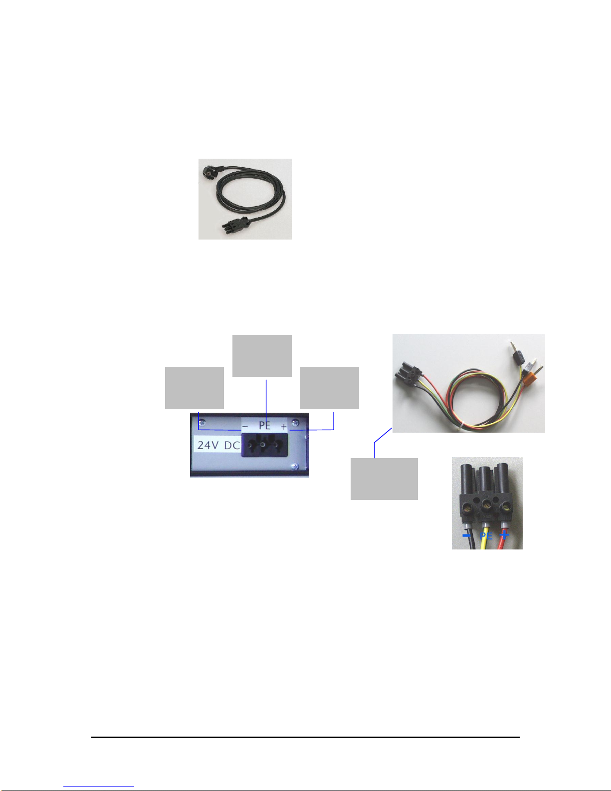
2.2.9.2 DC Power Supply ........................................................................................................................ 9
3INTERFACE CONFIGURATION............................................................................................ 10
3.1 VARIANT A................................................................................................................................ 10
3.2 VARIANT B................................................................................................................................ 11
3.3 VARIANT C................................................................................................................................ 12
3.4 VARIANT E................................................................................................................................ 12
3.5 VARIANT E3.............................................................................................................................. 13
3.6 VARIANT E2.............................................................................................................................. 13
3.7 VARIANT E2M........................................................................................................................... 14
3.8 VARIANT F................................................................................................................................ 15
3.9 VARIANT L ................................................................................................................................ 16
3.10 VARIANT P................................................................................................................................ 16
4TECHNICAL DATA ................................................................................................................ 17
5APPENDIX.............................................................................................................................. 20
5.1 BACKUP,RESTORE (ONLY FOR INDUSTRIAL PCS WITH WINDOWS XP PROFESSIONAL OS –
IPC191V3WIN)........................................................................................................................ 20
5.1.1 Restoration / Reinstallation.............................................................................................. 20
5.1.2 Backup............................................................................................................................. 20
5.2 IPC191V3 CAD DRAWING........................................................................................................ 20

Subject to alterations Version 2.2
IPCOMM GmbH - 2 - IPC191V3 Manual
Gundstraße 15 Copyright © 2012 IPCOMM GmbH
D-91056 Erlangen All rights reserved
1 Introduction
All technical information, descriptions and illustrations contained in this Operating, Maintenance and
Installation Manual remain our property and shall not be used otherwise than for operating this
System, nor shall they be copied, reproduced or passed on to third parties or brought to their notice
without our prior written consent.
The information represented in this manual is in keeping with current standards and is subject to later
alterations.
This manual contains important instructions referring to safe installation, commissioning, operation
and maintenance.
Read this manual carefully before starting up the protocol converter and observe the instructions.
In order to comply with the guidelines for electro-magnetic compatibility in industrial PCs (or other
variants) only CE-certified components are used in compliance with project-specific requirements.
It is to be noted that the Protocol Converter (IPC191V3) has not been protected against lightning and
the operator should, if desired, take appropriate protective precautions.
All trademarks and brand names contained in this user manual are for identification purposes only and
can be owned by their respective holders.
Finally we want to draw your attention to the fact that any warranties with respect to delivered goods
will be invalid in the event that:
Operation, servicing and maintenance are not carried out accurately according to the
instructions; repairs are not carried out by our personnel or without our prior written consent.
Commissioning is not carried out by our personnel or we have not given our approval for the
commissioning or the commissioning is carried out by untrained personnel.
The unit is used inadequately, incorrectly, negligently or inappropriately or for a purpose other
than that originally intended.
The serial number is removed from the product.
For your protection, observe the following safety precautions when setting up your equipment:
Follow all cautions and instructions marked on the equipment.
Ensure that the voltage and frequency of your power source match the voltage and frequency
inscribed on the equipment's electrical rating label.
Never push objects of any kind through openings in the equipment. Dangerous voltages may
be present. Conductive foreign objects could produce a short circuit that could cause fire,
electric shock, or damage to your equipment.
The industrial PC must be mounted on an equipment carrier (1U) in a 19” rack.
A free floating or unilateral mounting may cause defects.
All trademarks or brand marks mentioned in this document are used for identification and are property
of their respective owners.

Subject to alterations Version 2.2
IPCOMM GmbH - 3 - IPC191V3 Manual
Gundstraße 15 Copyright © 2012 IPCOMM GmbH
D-91056 Erlangen All rights reserved
2 Hardware Description
2.1 General
As hardware platform for the protocol converter a 19” industrial PC is used. This solution offers a high
degree on flexibility, performance and reliability.
Mounting and intensive tests of the industrial PC are done in our company.
Before and after a 48 hour burn-in test each device must run through a complete function test.
All components are cooled passively. Only if critical system temperatures have been reached two
independent housing fans are switched on automatically. Important for the selection of our
components are particular items like quality, availability and a high durability.
The industrial PC consists of a 19“ chassis (1U) with an integrated Dual PCI riser card for inserting the
appropriate cards.
The mains power supply are 90 –264 V AC, 127 –373 V DC auto range, optional 10 –36 V DC
power supply (other on request).
Figure 1: Front view Industrial PC
Power
Button
Power
LED
CompactFlash Card
CPU LED
or
HDD LED
COM 2
S/N, Model, Voltage
DVD-RW Drive
(Optional, with
Windows operating
system in scope of
delivery)

Subject to alterations Version 2.2
IPCOMM GmbH - 4 - IPC191V3 Manual
Gundstraße 15 Copyright © 2012 IPCOMM GmbH
D-91056 Erlangen All rights reserved
Figure 2 shows the reverse side of our Industrial PC. The pin assignments vary according to
execution. Overview of the different models can be found in chapter 3 Interface Configuration.
Figure 2: Overview Interfaces (example shows variant E2M with 8-port serial interface card
(PCI 2) and 2x Ethernet (PCI 1))
2.2 Hardware Components
2.2.1 Mainboard
The Mini-ITX Mainboard is an ultra-compact x86 platform with all the necessary interfaces. Its heart
consists of a fanless highly efficient embedded VIA processor. The mainboard provides one DIMM slot
for DDRII memory modules and supports up to 2GB system memory.
The following interfaces are provided by the CPU module:
3 x RS-232 Interface (model-specific)
2 x SATA
1 x LAN 10/100/1000 Mbps BaseT (RJ45), 3x LAN 10/100 Mbps BaseT (RJ45)
EIDE Interface
VGA Interface
Keyboard- / Mouse Port
USB
PCI
Monitor
VGA
LAN 4
Keyboard
LAN 1
COM 1
PCI 1
Main Power Supply
input
8 Port DB 9 male connector cable
for 8-port serial interface card
(optional: DB25 (male, female) )
PCI 2
Mouse
LAN 3
LAN 2

Subject to alterations Version 2.2
IPCOMM GmbH - 5 - IPC191V3 Manual
Gundstraße 15 Copyright © 2012 IPCOMM GmbH
D-91056 Erlangen All rights reserved
2.2.2 CPU-Module RS-232 Interfaces
The installed mainboard provides 3 serial interfaces. However, depending on the model these
interfaces are completely or only partly available at the chassis.
COM3 interface is active but reserved for internal purpose and cannot be used.
This interface type is used for COM 1
SERIAL PORT
RS-232 DTE
DB9 male connector
Pin
Direction
Description
1
INPUT
DCD Data Carrier Detect
2
INPUT
RXD Receive Data
3
OUTPUT
TXD Transmit Data
4
OUTPUT
DTR Data Terminal Ready
5
GND Ground
6
INPUT
DSR Data Set Ready
7
OUTPUT
RTS Request To Send
8
INPUT
CTS Clear To Send
9
INPUT
RI Ring Indicator
Figure 3: Pin Assignment of DB9 Interface (Computer) COM1-COM2
2.2.3 8-Port RS-232 Communication Board (RS-232 Interfaces for remote
communication)
Depending on the model each IPC191V3 can be equipped with up to two 8-port serial interface cards.
The following pin assignment is realized with an 8-port DB9 male connector cable (see Figure 2:
Overview Interfaces). Other cables (e.g. DB25) are possible on request.
SERIAL PORT
RS-232 DTE
DB9 male connector
Pin
Direction
Description
1
INPUT
DCD Data Carrier Detect
2
INPUT
RXD Receive Data
3
OUTPUT
TXD Transmit Data
4
OUTPUT
DTR Data Terminal Ready
5
GND Ground
6
INPUT
DSR Data Set Ready
7
OUTPUT
RTS Request To Send
8
INPUT
CTS Clear To Send
9
Figure 4: Pin Assignment of DB9 interface (Communication Board)

Subject to alterations Version 2.2
IPCOMM GmbH - 6 - IPC191V3 Manual
Gundstraße 15 Copyright © 2012 IPCOMM GmbH
D-91056 Erlangen All rights reserved
2.2.4 4-Port RS-232 Communication Board (RS-232 Interfaces for remote
communication)
Depending on the model each IPC191V3 can be equipped with up to two 4-port serial interface cards.
SERIAL PORT
RS-232 DTE
RJ45
Pin
Direction
Description
1
INPUT
DSR Data Set Ready
2
OUTPUT
RTS Request To Send
3
GND Ground
4
OUTPUT
TXD Transmit Data
5
INPUT
RXD Receive Data
6
INPUT
DCD Data Carrier Detect
7
INPUT
CTS Clear To Send
8
OUTPUT
DTR Data Terminal Ready
Figure 5: Pin Assignment of RJ45 interface (Communication Board)
2.2.5 Ethernet Interfaces
The industrial PC features up to four Ethernet interfaces generally. The connection is set up via one
10/100/1000 Mbps BaseT (RJ45) and three 10/100 Mbps BaseT (RJ45) interfaces. Further interfaces
with 10/100 Mbps or 10/100/1000 Mbps BaseT are possible on request.
Figure 6: Pin Assignment RJ45 interface

Subject to alterations Version 2.2
IPCOMM GmbH - 7 - IPC191V3 Manual
Gundstraße 15 Copyright © 2012 IPCOMM GmbH
D-91056 Erlangen All rights reserved
2.2.6 CompactFlash
The CompactFlash card serves as a mass storage device, i.e. for storing the operating system, the
applications and configuration data. As a result the disadvantages involved with the use of a rotating
hard disk are avoided, thus improving the reliability of the system substantially since a CompactFlash
has an MTBF of at least 1,000,000 hours.
The CompactFlash adapter is simply connected to the IDE bus of the CPU module and treated just
like a hard disk.
Figure 7: CompactFlash Adapter
When the power supply is switched off the CompactFlash card can simply be taken out or inserted
enabling a quick change to different hardware.
2.2.7 CMOS Lithium Battery
The onboard CMOS RAM stores system configuration data and has an onboard battery power supply.
The long-life Lithium battery has normally a lifetime of at least 5 years.
If the CMOS battery is empty and the CMOS information has been deleted, the CMOS-RAM is
programmed by the BIOS with default settings.
The converter can be operated faultlessly even if the CMOS RAM is not provided by the battery. After
the battery has been changed only time and date must be input.
For opening the case 6 screws on the top must be removed. The battery holder is soldered in the
Mainboard and well visible.
Attention: Open-frame power supplies are used. Because of this, the process should be carried out
only by experienced electronic engineers. The device must be completely disconnected from any
power supply. Before opening please push the power button (without electricity supply) several times
to eliminate residual voltages of the power supply.
Battery replacement must be carried out by qualified specialists.
CAUTION! Incorrect replacement might cause the danger of explosion. Replace the battery
exclusively by the same type (3 V DC, CR2032). Used batteries are to be disposed absolutely in
accordance with the manufacturer's instructions.
Please pay attention to the correct polarity!
Push to take
CompactFlash
out

Subject to alterations Version 2.2
IPCOMM GmbH - 8 - IPC191V3 Manual
Gundstraße 15 Copyright © 2012 IPCOMM GmbH
D-91056 Erlangen All rights reserved
2.2.8 CPU LED
The CPU LED shows the states of conversion software and operating system.
Following figure shows all possible indications:
Figure 8: CPU-LED indications
Attention! If the IPC191V3 is ordered without ipConv software and not as a replacement for an
existing project, an HDD-Activity LED is installed instead of the CPU-LED! The device name is then
labeled with an additional "-H", for example: "IPC191V3-H"
ON
OFF
Passive
Mode
(Standby)
0,5
s
ON
OFF
Active
Mode
0,5
s
5 s
ON
OFF
Software has
stopped

Subject to alterations Version 2.2
IPCOMM GmbH - 9 - IPC191V3 Manual
Gundstraße 15 Copyright © 2012 IPCOMM GmbH
D-91056 Erlangen All rights reserved
2.2.9 Power Supply
Power supplies with different input voltages can be used in the IPC191V3. Please pay attention to the
correct polarity and input voltage. The input voltage of the respective device is labeled on top of the
housing (see Figure 1: Front view Industrial PC).
2.2.9.1 AC Power Supply
By using AC voltages a specific power supply cable (see figure below) is supplied. Please use this
cable exclusively.
Figure 9: Power Cable
2.2.9.2 DC Power Supply
By using DC voltages only a male connector is supplied. This connector has to be used. By
connecting the cable with the male connector the correct polarity must be kept. The wire cross-section
must be at least 1,5 mm².
Figure 10: DC Power Connection socket
Power Supply
Input
-
Power Supply
Input
+
Connection
for Earth
Potential
DC Power Cable
(Example, not
included in
delivery)

Subject to alterations Version 2.2
IPCOMM GmbH - 10 - IPC191V3 Manual
Gundstraße 15 Copyright © 2012 IPCOMM GmbH
D-91056 Erlangen All rights reserved
3 Interface Configuration
The following tables represent the configuration of the individual interfaces of miscellaneous variants.
3.1 Variant A
Assembly
Linux
Device
I/O port
IRQ
Label
Connector
Mainboard
ttyS0
3F8
4
IOIOI (Chassis
rear)
DB9ST
ttyS1
2F8
3
IOIOI (Chassis
front)
DB9ST
ttyS2
3E8
5
CPU (Diagnose)
NOT Connected
eth0
PCI (Onboard)
Auto
LAN1
RJ45
eth1
PCI (Onboard)
Auto
LAN2
RJ45
eth2
PCI (Onboard)
Auto
LAN3
RJ45
eth3
PCI (Onboard)
Auto
LAN4
RJ45
UART
Adapter 8X
ttyS3
PCI (Slot 2)
Auto
COM4
DB9ST
ttyS4
PCI (Slot 2)
Auto
COM5
DB9ST
ttyS5
PCI (Slot 2)
Auto
COM6
DB9ST
ttyS6
PCI (Slot 2)
Auto
COM7
DB9ST
ttyS7
PCI (Slot 2)
Auto
COM8
DB9ST
ttyS8
PCI (Slot 2)
Auto
COM9
DB9ST
ttyS9
PCI (Slot 2)
Auto
COM10
DB9ST
ttyS10
PCI (Slot 2)
Auto
COM11
DB9ST

Subject to alterations Version 2.2
IPCOMM GmbH - 11 - IPC191V3 Manual
Gundstraße 15 Copyright © 2012 IPCOMM GmbH
D-91056 Erlangen All rights reserved
3.2 Variant B
Assembly
Linux
Device
I/O port
IRQ
Label
Connector
Mainboard
ttyS0
3F8
4
IOIOI (Chassis
rear)
DB9ST
ttyS1
2F8
3
IOIOI (Chassis
front)
DB9ST
ttyS2
3E8
5
CPU (Diagnose)
NOT Connected
eth0
PCI (Onboard)
Auto
LAN1
RJ45
eth1
PCI (Onboard)
Auto
LAN2
RJ45
eth2
PCI (Onboard)
Auto
LAN3
RJ45
eth3
PCI (Onboard)
Auto
LAN4
RJ45
UART
Adapter 8X
ttyS3
PCI (Slot 1)
Auto
COM4
DB9ST
ttyS4
PCI (Slot 1)
Auto
COM5
DB9ST
ttyS5
PCI (Slot 1)
Auto
COM6
DB9ST
ttyS6
PCI (Slot 1)
Auto
COM7
DB9ST
ttyS7
PCI (Slot 1)
Auto
COM8
DB9ST
ttyS8
PCI (Slot 1)
Auto
COM9
DB9ST
ttyS9
PCI (Slot 1)
Auto
COM10
DB9ST
ttyS10
PCI (Slot 1)
Auto
COM11
DB9ST
UART
Adapter 8X
ttyS11
PCI (Slot 2)
Auto
COM12
DB9ST
ttyS12
PCI (Slot 2)
Auto
COM13
DB9ST
ttyS13
PCI (Slot 2)
Auto
COM14
DB9ST
ttyS14
PCI (Slot 2)
Auto
COM15
DB9ST
ttyS15
PCI (Slot 2)
Auto
COM16
DB9ST
ttyS16
PCI (Slot 2)
Auto
COM17
DB9ST
ttyS17
PCI (Slot 2)
Auto
COM18
DB9ST
ttyS18
PCI (Slot 2)
Auto
COM19
DB9ST

Subject to alterations Version 2.2
IPCOMM GmbH - 12 - IPC191V3 Manual
Gundstraße 15 Copyright © 2012 IPCOMM GmbH
D-91056 Erlangen All rights reserved
3.3 Variant C
Assembly
Linux
Device
I/O port
IRQ
Label
Connector
Mainboard
ttyS0
3F8
4
IOIOI (Chassis
rear)
DB9ST
ttyS1
2F8
3
IOIOI (Chassis
front)
DB9ST
ttyS2
3E8
5
CPU (Diagnose)
NOT Connected
eth0
PCI (Onboard)
Auto
LAN1
RJ45
eth1
PCI (Onboard)
Auto
LAN2
RJ45
eth2
PCI (Onboard)
Auto
LAN3
RJ45
eth3
PCI (Onboard)
Auto
LAN4
RJ45
Ethernet
Adapter 1X
eth4
PCI (Slot 1)
Auto
LAN5
RJ45
UART
Adapter 8X
ttyS3
PCI (Slot 2)
Auto
COM4
DB9ST
ttyS4
PCI (Slot 2)
Auto
COM5
DB9ST
ttyS5
PCI (Slot 2)
Auto
COM6
DB9ST
ttyS6
PCI (Slot 2)
Auto
COM7
DB9ST
ttyS7
PCI (Slot 2)
Auto
COM8
DB9ST
ttyS8
PCI (Slot 2)
Auto
COM9
DB9ST
ttyS9
PCI (Slot 2)
Auto
COM10
DB9ST
ttyS10
PCI (Slot 2)
Auto
COM11
DB9ST
3.4 Variant E
Assembly
Linux
Device
I/O port
IRQ
Label
Connector
Mainboard
ttyS0
3F8
4
IOIOI (Chassis
rear)
DB9ST
ttyS1
2F8
3
IOIOI (Chassis
front)
DB9ST
ttyS2
3E8
5
CPU (Diagnose)
NOT Connected
eth0
PCI (Onboard)
Auto
LAN1
RJ45
eth1
PCI (Onboard)
Auto
LAN2
RJ45
eth2
PCI (Onboard)
Auto
LAN3
RJ45
eth3
PCI (Onboard)
Auto
LAN4
RJ45
Ethernet
Adapter 1X
eth4
PCI (Slot 1)
Auto
LAN5
RJ45
Ethernet
Adapter 1X
eth5
PCI (Slot 2)
Auto
LAN6
RJ45

Subject to alterations Version 2.2
IPCOMM GmbH - 13 - IPC191V3 Manual
Gundstraße 15 Copyright © 2012 IPCOMM GmbH
D-91056 Erlangen All rights reserved
3.5 Variant E3
Assembly
Linux
Device
I/O port
IRQ
Label
Connector
Mainboard
ttyS0
3F8
4
IOIOI (Chassis
rear)
DB9ST
ttyS1
2F8
3
IOIOI (Chassis
front)
DB9ST
ttyS2
3E8
5
CPU (Diagnose)
NOT Connected
eth0
PCI (Onboard)
Auto
LAN1
RJ45
eth1
PCI (Onboard)
Auto
LAN2
RJ45
eth2
PCI (Onboard)
Auto
LAN3
RJ45
eth3
PCI (Onboard)
Auto
LAN4
RJ45
Ethernet
Adapter 1X
eth4
PCI (Slot 2)
Auto
LAN5
RJ45
3.6 Variant E2
Assembly
Linux
Device
I/O port
IRQ
Label
Connector
Mainboard
ttyS0
3F8
4
IOIOI (Chassis
rear)
DB9ST
ttyS1
2F8
3
IOIOI (Chassis
front)
DB9ST
ttyS2
3E8
5
CPU (Diagnose)
NOT Connected
eth0
PCI (Onboard)
Auto
LAN1
RJ45
eth1
PCI (Onboard)
Auto
LAN2
RJ45
eth2
PCI (Onboard)
Auto
LAN3
RJ45
eth3
PCI (Onboard)
Auto
LAN4
RJ45
Ethernet
Adapter 2X
eth4
PCI (Slot 1)
Auto
LAN5
RJ45
eth5
PCI (Slot 1)
Auto
LAN6
RJ45

Subject to alterations Version 2.2
IPCOMM GmbH - 14 - IPC191V3 Manual
Gundstraße 15 Copyright © 2012 IPCOMM GmbH
D-91056 Erlangen All rights reserved
3.7 Variant E2M
Assembly
Linux
Device
I/O port
IRQ
Label
Connector
Mainboard
ttyS0
3F8
4
IOIOI (Chassis
rear)
DB9ST
ttyS1
2F8
3
IOIOI (Chassis
front)
DB9ST
ttyS2
3E8
5
CPU (Diagnose)
NOT Connected
eth0
PCI (Onboard)
Auto
LAN1
RJ45
eth1
PCI (Onboard)
Auto
LAN2
RJ45
eth2
PCI (Onboard)
Auto
LAN3
RJ45
eth3
PCI (Onboard)
Auto
LAN4
RJ45
Ethernet
Adapter 2X
eth4
PCI (Slot 1)
Auto
LAN5
RJ45
eth5
PCI (Slot 1)
Auto
LAN6
RJ45
UART
Adapter 8X
ttyS3
PCI (Slot 2)
Auto
COM4
DB9ST
ttyS4
PCI (Slot 2)
Auto
COM5
DB9ST
ttyS5
PCI (Slot 2)
Auto
COM6
DB9ST
ttyS6
PCI (Slot 2)
Auto
COM7
DB9ST
ttyS7
PCI (Slot 2)
Auto
COM8
DB9ST
ttyS8
PCI (Slot 2)
Auto
COM9
DB9ST
ttyS9
PCI (Slot 2)
Auto
COM10
DB9ST
ttyS10
PCI (Slot 2)
Auto
COM11
DB9ST

Subject to alterations Version 2.2
IPCOMM GmbH - 15 - IPC191V3 Manual
Gundstraße 15 Copyright © 2012 IPCOMM GmbH
D-91056 Erlangen All rights reserved
3.8 Variant F
Assembly
Linux
Device
I/O port
IRQ
Label
Connector
Mainboard
ttyS0
3F8
4
IOIOI (Chassis
rear)
DB9ST
ttyS1
2F8
3
IOIOI (Chassis
front)
DB9ST
ttyS2
3E8
5
CPU (Diagnose)
NOT Connected
eth0
PCI (Onboard)
Auto
LAN1
RJ45
eth1
PCI (Onboard)
Auto
LAN2
RJ45
eth2
PCI (Onboard)
Auto
LAN3
RJ45
eth3
PCI (Onboard)
Auto
LAN4
RJ45
UART
Adapter 4X
ttyS3
PCI (Slot 1)
Auto
COM4
RJ45
ttyS4
PCI (Slot 1)
Auto
COM5
RJ45
ttyS5
PCI (Slot 1)
Auto
COM6
RJ45
ttyS6
PCI (Slot 1)
Auto
COM7
RJ45
UART
Adapter 4X
ttyS11
PCI (Slot 2)
Auto
COM12
RJ45
ttyS12
PCI (Slot 2)
Auto
COM13
RJ45
ttyS13
PCI (Slot 2)
Auto
COM14
RJ45
ttyS14
PCI (Slot 2)
Auto
COM15
RJ45
The COM ports of the UART adapter are configured as follows:
Figure 11: UART COM port configuration

Subject to alterations Version 2.2
IPCOMM GmbH - 16 - IPC191V3 Manual
Gundstraße 15 Copyright © 2012 IPCOMM GmbH
D-91056 Erlangen All rights reserved
3.9 Variant L
Assembly
Linux
Device
I/O port
IRQ
Label
Connector
Mainboard
ttyS0
3F8
4
IOIOI (Chassis
rear)
DB9ST
ttyS1
2F8
3
IOIOI (Chassis
front)
DB9ST
ttyS2
3E8
5
CPU (Diagnose)
NOT Connected
eth0
PCI (Onboard)
Auto
LAN1
RJ45
eth1
PCI (Onboard)
Auto
LAN2
RJ45
eth2
PCI (Onboard)
Auto
LAN3
RJ45
eth3
PCI (Onboard)
Auto
LAN4
RJ45
3.10 Variant P
Assembly
Linux
Device
I/O port
IRQ
Label
Connector
Mainboard
ttyS0
3F8
4
IOIOI (Chassis
rear)
DB9ST
ttyS1
2F8
3
IOIOI (Chassis
front)
DB9ST
ttyS2
3E8
5
CPU (Diagnose)
NOT Connected
eth0
PCI (Onboard)
Auto
LAN1
RJ45
eth1
PCI (Onboard)
Auto
LAN2
RJ45
eth2
PCI (Onboard)
Auto
LAN3
RJ45
eth3
PCI (Onboard)
Auto
LAN4
RJ45
Profibus
Adapter 1X
PCI (Slot 1)
Auto
Profibus
Profibus
UART
Adapter 8X
ttyS3
PCI (Slot 2)
Auto
COM4
DB9ST
ttyS4
PCI (Slot 2)
Auto
COM5
DB9ST
ttyS5
PCI (Slot 2)
Auto
COM6
DB9ST
ttyS6
PCI (Slot 2)
Auto
COM7
DB9ST
ttyS7
PCI (Slot 2)
Auto
COM8
DB9ST
ttyS8
PCI (Slot 2)
Auto
COM9
DB9ST
ttyS9
PCI (Slot 2)
Auto
COM10
DB9ST
ttyS10
PCI (Slot 2)
Auto
COM11
DB9ST

Subject to alterations Version 2.2
IPCOMM GmbH - 17 - IPC191V3 Manual
Gundstraße 15 Copyright © 2012 IPCOMM GmbH
D-91056 Erlangen All rights reserved
4 Technical Data
Chassis
19“ rack mount chassis (1U)
Dual PCI riser card
The Industrial PC doesn’t have any CPU- and Power supply fan. The
hardware is equipped with two passive chassis fans which are switched
on only if a certain CPU temperature and system temperature respectively
has been exceeded (configurable).
MTBF
> 100,000h
Power Supply AC
Fanless
90 –264 V AC, 127 –373 V DC autorange
Input frequency: 47 –63 Hz
Hold up time: ≥20 msec, 230 VAC
Power consumption: max. 50 W (depending on the used type)
CE/TÜV certified (EN 60950-1, UL 60950-1)
Power Supply DC
(optional)
Fanless
10-36 V DC
Hold up time: >1 msec at +24 VDC and rated load
Power consumption: max. 50 W (depending on the used type)
CE/TÜV certified (UL / EN 60950-1)
Mainboard
VIA Nano 1 GHz, fanless CPU (up to 3x faster than IPC191V2 CPU)
DDR2 RAM max. 2 GB
IDE interface
SATA interface
2 x serial ports
Real-time clock/calendar
1 x RJ45 10/100/1000BaseT LAN interface, 3 x RJ45 10/100BaseT LAN
interface onboard, more on request (over PCI)
4 x USB 2.0 (two at front side, two at back side), more on request
RAID SATA functionality (RAID Level 0 or RAID Level 1)
Serial Cards
Up to sixteen serial RS-232 ports
DB9 male connectors, optional RJ45, DB25 (male, female)
Baud rate 50 bps to 921,600 bps transmission speed
16KV ESD protection
Diagnostics
Power LED
LED to show different software conditions
Additional Functions
Battery buffered real time clock (RTC)
Reset

Subject to alterations Version 2.2
IPCOMM GmbH - 18 - IPC191V3 Manual
Gundstraße 15 Copyright © 2012 IPCOMM GmbH
D-91056 Erlangen All rights reserved
Mass Storage CF
Rugged CompactFlash, industrial –grade
Max. 16 GB supported
MTBF ≥ 1,000,000 hours
No moving parts
Shock: 1000 G max.
Removable flash card
Bad Block Scanning/Handling
Static Wear-Leveling System
6-Bit ECC
2,000,000 write/erase cycles
Vibration: 15 G peak to peak max.
Very short access time
Mass Storage SATA
HDD Raid Level 1 or 0
possible (optional)
Two server HDDs, for continuous operation
Max. 2 TB
MTBF ≥ 1,200,000 hours
Mass Storage SATA
SSD Raid Level 1 or 0
possible (optional)
No moving parts
Max. 128 GB supported
Very short access time
Very high write/read performance
Supported Operating
Systems
Windows XP Professional
Linux
Optical Drive (optional)
CD/DVD writer with Slot-in technology
Video
Standard VGA interface
Operating Environment
Operating temperature: 0° C to 50° C
Storage temperature: 0° C to 60° C
Relative humidity (non condensing): 5 % to 95 %

Subject to alterations Version 2.2
IPCOMM GmbH - 19 - IPC191V3 Manual
Gundstraße 15 Copyright © 2012 IPCOMM GmbH
D-91056 Erlangen All rights reserved
General
All components are CE certified and tested according to type of test
EN 61000-6-2:2005; EN 61000-6-4:2007
Height: 1 U
Dimension (W x H x D): 19" x 1.75" x 15"
(482.6 mm x 44.45 mm x 381 mm)
Weight: 5.80 kg
Assembled by IPCOMM GmbH/Germany
This manual suits for next models
1
Table of contents
Other IPCOMM Industrial PC manuals
Popular Industrial PC manuals by other brands

AXIOMTEK
AXIOMTEK tBOX321-870-FL Series Quick installation guide

IEI Technology
IEI Technology uIBX-230-BT Series user manual

IEI Technology
IEI Technology PM-BT Quick installation guide

adstec
adstec IRF3000 Series quick start guide

AXIOMTEK
AXIOMTEK eBOX630-100-FL Series user manual

Siemens
Siemens SIMATIC IPC427E operating instructions