IRadimed 3880 MRI User manual

3880 MRI Patient Monitor System
Reference Guide
www.IRadimed.com

2
PODs, Tablet, and Base Station
3880 System Overview
1
3880 System Overview
3880 Monitor
Monitor Front
Battery
POD Charging Dock
CO2Exhaust Port
Monitor LeftMonitor Right
NIBP Port
Temperature Port
Settings Power Knob
Alarm Silence
Touch Screen
Standby
Trend
Record
NIBP
CO2Port
Channel Select Button
Connection Indicator
Channel Selection Light
Channels 5 to 8 Indicator
Power ON Button
Power OFF Button Power Button
Alarm Silence
Settings
Removable TabletBase Station
Standby
Trend
Record
Channel
Channel Select Button
Tablet Charge Status
Record Printer
Battery Status
NIBP

Screen Overview
4
Screen Overview
3
Signal Indicator Battery Statuses
Patient Type
Admit/Discharge
Alarm Indicators
Monitor’s Clock
Wireless Channel Number
ECG Waveform
NonInvasive Blood Pressure Readings
ECG Heart Rate
Pulse Rate Readings
Dynamic Trends
Respertory Rate Readings
SpO2 Readings
EtCO2 Readings
CO2 Waveform
SpO2 Waveform
Temperature Readings
Auto Timer
Expired (top)/Inspired (bottom) Gas Readings
MAC Readings
Alarm Example
Alarm Priority Physiological Alarms Technical Alarms
On Screen Alarms

6
1.2 | Power and Charging the Base Station and Tablet
Initial Setup
a. Ensure the Base Station is plugged into a power source. Toggle the switch up on the reverse side of
the Base Station to power it ON.
b. Press and hold the power button on the Tablet for two seconds to power it ON.
5
Initial Setup
1.1| Power and Charging the Monitor
b. Connect the power cable to the power port to charge
the battery and power the Monitor.
c. Turn the white dial on the front of the Monitor to
the right to power it ON.
a. Insert the battery on the rear side of the Monitor
and push until the battery’s lock clicks.

8
1.4 | Powering the 3886 Multi-Gas Module
Initial Setup
a. Ensure the Multi-Gas Module is plugged into a power source.
b. Toogle the switch up on the rear side of the 3886 Multi-Gas Module to power it ON.
7
1.3 | Powering and Charging the PODs
Initial Setup
a. Remove the selected POD from the charging dock on
either the side of the Monitor or the Base Station’s dock.
b. Power on the selected POD by pressing the Green button
on the POD’s face.
c. The selected POD’s power indicator light will illuminate
when the POD has been powered on.

Wireless Channel Connectivity
10
2.2 | Changing Wireless Channels on the Wireless PODs
9
Wireless Channel Conectivity
2.1 | Changing Wireless Channels on the 3880 System
c. If the Tablet is not docked to the Base Station, press the yellowyellow
CH Select button to cycle through the channels.
a. Press the signal inidcator icon on screen.
b. The channel list will drop down. Click the desired channel
and the Monitor will automatically set the new channel.
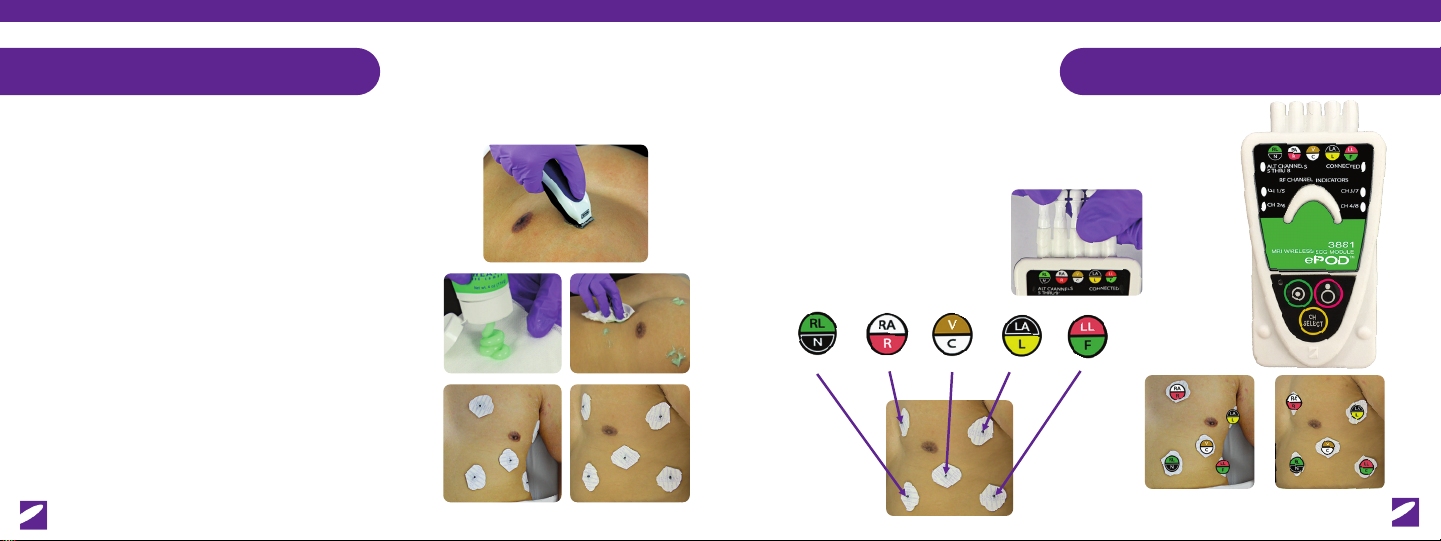
a. To place the POD into channel select mode, press the yellowyellow CH Select Button
on each POD
b. The Pod’s green light will begin to blink.
c. Continuously press the yellowyellow CH Select button to cycle through
channels. Alt Channels light will illuminate if on channels 5 to 8.
- The process of changing the channel on the Tablet is
identical to the Monitor.
- If the tablet is docked, the Base Station’s channel will
automatically sync with the Tablet.
d. Once synced with the 3880, the connected light will illuminate.
Additionally the Battery Status will show on the Monitor.

b. Place the leadwires as follows:
a. Connect the leadwires to its matching colored coded
indicator on the ePOD. Ensure the wire connectors are ush with the ePOD.
Electrocardiogram (ECG)
3.2 | Connecting Electrodes on Patients
12
Right Leg Right Arm V Lead Left Arm Left Leg
Patient Front Patient Left
3.1 | Patient Preperation and Electrode Application
a. Select an application site and remove any hair from
the area if necessary.
Electrocardiogram (ECG)
11
Patient Front Patient Left
b. Apply a sucient ammount of skin prep gel to
a gauze pad or cloth.
c. Using a circular motion, rub the selected electrode sites
with skin prep gel. Remove any excess gel from the patient
with a clean gauze pad or cloth.
d. Place the electrodes on the patient’s body and avoid placement
on top of dense breast tissue. Alternative placement under
breast tissue is recommended.

Electrocardiogram (ECG)
3.4 | ECG for Neonatal Applications
a. Do NOT over abrade the patient’s skin as neonatal skin is very sensitive.
a. Route the leadwires and POD away from the
RF Coil. As a best practice, place the PODs in the
“Line of Sight”to the Monitor.
14
b. It is NOT required to seperate the electrodes.
c. Place the Hextrode™ on the center of the patient’s body.
d. Ensure the 3880 Monitor’s patient type has been switched to Neonatal.
Electrocardiogram (ECG)
3.3 | Leadwire Management
13
Head Coil Example
Chest Coil Example

16
Pulse Oxymetry oPOD
4.2 | SpO2Neonatal Application
a. Ensure the grips are NOT too tight.
Disposable Reusable
a. Select the correct SpO2applicator for the patient. Insert the ber-optic cable emitting the red light
into the opening on the grips marked by a star or number. Secure grips to the patient by align the
ber-optic sensor over the nail bed and stick it down.
b. Insert the receiving ber-optic into the grip’s secondary opening marked by a circle. Place the receiving
ber-optic on the pad of the patient’s nger.
c. Wrap the wings of the grips around the patients nger.
b. Place the appropriate grip on the patient’s hand, wrist, or foot.
c. Ensure the 3880 Monitor’s patient type has been switched
to Neonatal.
4.1 | SpO2Adult Application
15
Pulse Oxymetry oPOD

18
Temperature
6.1 | Fiber-Optic Thermometer Application
17
5.1 | EtCO2Application
Respiration Capnography
a. Remove any dustcaps from the fiber-optic themometer
and its port on the Monitor.
a. Turn the Agents parameter OFF.
b. Attach the Disk Filter to the CO2port on the monitor, and connect an 1841 sample line to the disk lter.
c. Connect the sample line to the cannula or airway adapter. Apply the nasal prongs and ear loops.
b. Line up and insert the ber-optic thermometer into the keyed port
and push and rotate clockwise.
c. Place the ber-optic thermometer on the patient in a location where the
patient’s skin touches all sides of thermometer’s tip and secure
with medical tape.

8.1| Invasive Blood Pressure Application
20
Invasive Blood Pressure ipPOD
19
Noninvasive Blood Pressure
7.1| NIBP Clinical Application
a. Connect the NIBP Hose to the 3880 Monitor
3883-1* 3883-2* 3883-3*
a. Turn on the IBP1 and/or IBP2 with the toggle button in
the Parameter Setup Menu.
b. Connect the ipPOD to the transducer using one of the three connectors.
d. Close the transducer to start the IBP readings.
e. Add the IBP Label from the IBP Menu on the main screen.
c. Follow your facility’s policy on priming a transducer, open to room air. Press
the IBP1 or IBP2 section on the monitor’s screen. Press the button
to calibrate the transducer.
b. Align the cu on the patient so the arrow is along the
patient’s artery.
c. Click the NIBP Box to open the NIBP Menu on screen.
Select Auto Cycle Time and set to desired time interval.
d. Press the NIBP button to start automatic readings.

9.2| 3886 Multi-Gas Module Application
3886 Multi-Gas Module
22
3886 Multi-Gas Module
9.1| Conguring the 3880 Monitor for the 3886 Multi-Gas Module
21
b. Activate the Agents feature on the Monitor by pressing the button and then
pressing the Button.
a. Ensure the 1887 antenna is attached to the rear side of the Monitor. a. Once connected, insert the nomoline into the 3886 Multi-Gas Module.
Be aware, the 3886 Multi-Gas Module is MR Conditional
b. Connect the cannula or airway adapter’s sample line to the nomoline.
Gases are Detected Ready to Measure Gases Multi-Gas Module is Calibrating
Error with the Multi-Gas Module Error with Nomoline
Multi-Gas Module LED Light Color Codes
c. Turn the Agents and/or MAC parameters ON
and push the back button twice.
d. Press the CO2 section of the Monitor’s sceen to open the menu. Click the
Agents Channel to connect the 3886 Module to the Monitor.
e. The connection light on the 3886 Multi-Gas Module
will illuminate when connected.

Refer to the 3880 Operation Manual (item number 1200) for further instruction.
Information subject to change.
©IRadimed Corporation 2020 - All rights reserved
* Items number 3883-1, 3883-2, 3883-3 ship from Iradimed as a complete ipPOD.
Each connector has its own item number, 1861, 1862, and 1863 respectively.
This guide is not intended to replace your operator’s manual. Please refer to your operator’s manual
for use, and other training documentation. Contact the technical support team or clinical applications
team if you have any further questions about your device or the operation of the equipment.
1194_REV B. 1025 Willa Springs Drive, Winter Springs, FL 32708 | (407) 677-8022
Scan For
Training Videos
Table of contents
Other IRadimed Medical Equipment manuals
Popular Medical Equipment manuals by other brands

Masimo
Masimo LNC MP Series manual

Fresenius Kabi
Fresenius Kabi APPLIX SMART Instructions for use

Petra electric
Petra electric DT 10 Instructions for use

3B Medical
3B Medical Stratus 5 user manual

Osprey Medical
Osprey Medical DyeVert Plus EZ HV-EZ Series Instructions for use

Bionix
Bionix SecureVac SVRT-7130 Instructions for use