Ironmaster IM2000 Quick reference guide

Assembly & Operating Instructions
Ironmaster IM2000
Assembly and Use Instructions
The IM2000 is a self-spotting weight training system. Built in upper and lower pulleys allow for
various cable exercises and the lifting bar can quickly and easily be locked out at many levels for
safety without the need for a spotter for lifting and pressing exercises. Secondary safety stops
add even more safety if needed. Bar and weight storage bars will hold Standard or Olympic style
weight plates. The IM2000 is designed to be used in conjunction with Ironmaster products and
attachments, but can accommodate other brands of plates, cable attachments and benches.
Weight rating is 1000 lbs/450 KGS for the frame and lifting bar. Cable System is rated for 350
lbs/159 KGS. Ironmaster recommends 2 people for assembly. Refer to this manual or the Iron-
master web site for further details regarding usage of the IM2000 and be sure to understand all
safety warning labels.
Box contents
First, locate the HARDWARE KIT. Make sure to check that all parts are present by referring to
the parts list prior to assembly. Should any parts be broken or missing, please contact your near-
est Ironmaster dealer or Ironmaster directly using the contact information provided in this manual.
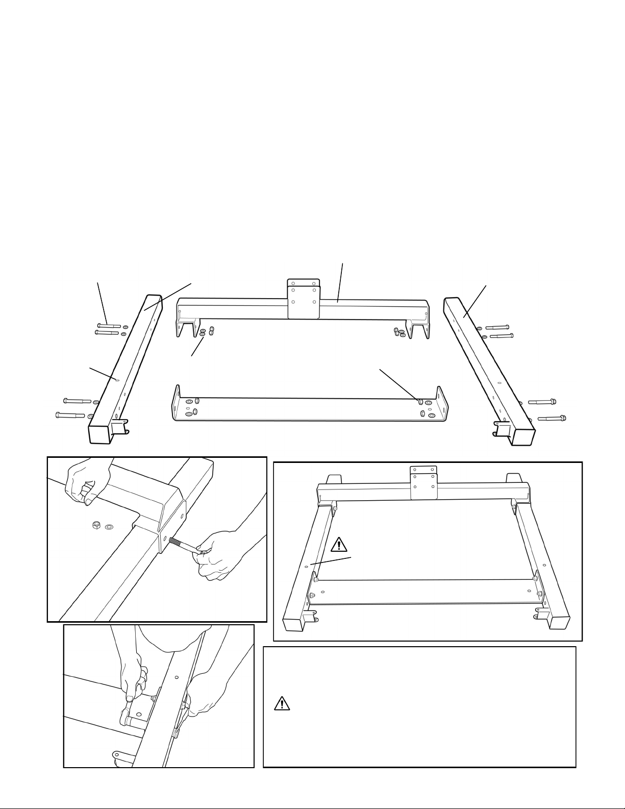
STEP ONE: Locate the following parts. L/R BASE LEGS/BASE CENTER/FOOTPLATE. You will
also require 8x M12x100bolts/16x M12 Washers and 8x Nylock nuts. Please see illustration for
correct orientation prior to assembly.
M12x100mm bolt
Nylock Nut
M12 washer
BASE LEG
BASE CENTER
BASE LEG
FOOTPLATE
First, install BASE CENTER over and onto the BASE LEGS. Then,
attach the FOOTPLATE to the BASE LEGS and after making sure
all botls are aligned properly, tighten entire assembly.
2 wrenches are needed to fully tighten the Nylock nuts!
NOTE: Before proceeding to step two, make sure that the
BASELEG holes to mount the SLIDE RAILS are in the correct ori-
entation (small hole facing upward).
Completed Step 1 assembly
Install BASE CENTER
onto BASE LEGS
Install FOOTPLATE
Small hole faces
upward
Small hole faces upward on BASE LEG to
mount SLIDE RAILS in STEP TWO

STEP TWO: Locate the following parts. L/R SLIDE RAILS/Slide Rail Allen wrench (included)/2x
1/2”x25mm bolts and Spring Washers . CAUTION: Aligning the SLIDE RAILS and BASE
FRAME assembly will require two people.
With two people, tilt the
BASE FRAME assembly
and install the 1/2”x25mm
bolts/washers from under-
neath the BASE FRAME
assembly and into the
SLIDE RAIL as shown.
NOTE: Make sure holes
are facing forward, and
the end with the holes
closet to the bottom of the
SLIDE RAIL fit into the
BASE assembly as
shown.
Check that the base of
SLIDE RAIL is lined up
Parallel to the BASE LEG
before securing.
Repeat procedure with
SLIDE RAIL
BASE FRAME ASSEMBLY
Installing 1/2”x25mm bolt and
washer through BASE FRAME
into SLIDE RAIL
BASE LEG
Prior to Standing completed assembly, check that 1.
Bolts attaching SLIDE RAILS to BASEFRAME assembly
are properly tightened and 2. The SLIDE RAILS are in-
stalled in the correct orientation eg; holes facing forward
and parallel to the BASE LEGS.
Completed Step 2 assembly
Installing opposite SLIDE RAIL
showing correct orientation
Incorrect
Correct
Correct

STEP THREE: Locate the following parts. 2x SAFETY STOPS/2x SPRINGS and LIFTING BAR.
No additional hardware is required for this portion of the assembly.
SAFETY STOP
SPRING
Slide SAFETY STOP and SPRING over top of SLIDE
RAIL as shown. Note SAFETY STOP hook faces down-
ward and toward front so as to align with SLIDE RAIL
holes. Spring simply rests on top of the SAFETY STOP.
Repeat on opposite SLIDE RAIL.
Next, install LIFTING BAR over top of SLIDE RAILS with
CHIN UP BAR safety hooks in the correct orientation
(CHIN UP BAR hooks facing same direction/able to lock
in same positional orientation as SAFETY STOP hook.
NOTE: When not in use, safety stop should be stored all
the way down to the base as shown left.
CAUTION: 2 People are strongly recommended for
ease of alignment and to avoid possible injury.
LIFTING BAR
Completed Step 3 assembly
Check for correct
orientation when
installing LIFT-
ING BAR. Lock
out pins swing
downward to
lock into position
Use care when in-
stalling LIFTING BAR
to avoid damaging the
bushings or scratch-
ing the SLIDE RAILS

STEP FOUR: Locate the following parts. 1x REAR SPINE/1x TOP CENTER and 1x CROSS-
MEMBER. You will also need 4x M12x 100mm bolts/8x M12 Washers and 4x Nylock Nuts for
the SPINE and 2x M12x100mm Bolts/4x M12 Washers and 2x Nylock Nuts for the TOP CEN-
TER/CROSSMEMBER assembly.
SPINE
With two people, install the
SPINE onto the BASE ASSEM-
BLY as shown, using the above
mentioned bolts to secure. Note
insert the M12x100mm bolt/M12
washer front to rear and secure
from back with M12 washer and
nylock nut.
Do not fully tighten yet.
Next, with 2x M12x100mm bolts/4x M12 washers
and 2x nylock nuts, assemble CROSSMEMBER
Into bottom of TOP CENTER as shown.
Tighten firmly.
M12 washer
M12x100mm bolt
Nylock Nut
TOP CENTER
CROSS MEMBER
TOP CENTER
CROSS MEMBER

STEP FIVE: Attach the TOP CENTER/CROSSMEMBER assembly to the SPINE/SLIDE RAILS.
Locate the following parts: 2x 1/2 inch x 100mmbolts (separately packaged in the bolt pack) and 2x
M12x180mm bolts/2x M12 washers and 2x nylock nuts.
Prepackaged 1/2 inch” x 100mm bolts
for CROSSMEMBER into SLIDE RAIL
Lift TOP CENTER assembly up onto the SLIDE RAILS and SPINE.
CROSSMEMBER TO SLIDE RAIL will use the 2x 1/2” x 100bolts. Use
the same Allen wrench provided for STEP 2 of the assembly.
Rear of TOP CENTER Bolts to SPINE using 2x M12 x 180mm bolts.
CAUTION: 2 People are strongly recommended for ease of alignment
and to avoid possible injury.
TIP: Don’t tighten until you are sure that the SLIDE RAILS have not
moved, and the entire assembly is square. Slide the LIFTING BAR up
and down the SLIDE RAILS. It should not bind, and the safety hooks
should locate in the same position on both sides of the SLIDE RAILs prior
to tightening the assembly. This may take a few tries.
Once you have determined fit and function are correct, move the LIFTING
BAR to the highest position on the SLIDE RAILS and tighten all four bolts
Once the assembly is complete find the SILICONE SPRAY (included)
and generously apply to both SLIDE RAILS.
TOP CENTER/CROSSMEMBER
assembly

STEP FIVE: Locate the following parts and hardware. 4x PLATE HOLDERS/8x STAND OFF plas-
tic spacers/1x J-HOOK /4x M10x 40mm bolts and 4x M10 washers.
First, slide the 4x PLATE HOLDERS into the
SPINE.
Next, Install the M10x40mm bolts/M10 washers
through the bottom three holes located in the
rear of the SPINE and secure the PLATE HOLD-
ERS into position. Tighten.
Then, slide the 8x STAND OFF plastic spacers
onto the PLATE HOLDERS.
Next, locate the J-hook (shown below) and install,
through the uppermost hole in SPINE, the
M10x40mm bolt, M10 washer and the J-hook as
shown.
STAND OFF plastic
spacer
J-HOOK
PLATE HOLDER
STAND OFF plastic
spacer

STEP SIX: Locate the following parts and hardware. 1x UPPER PULLEY CABLE/2x M12x45mm
bolts/M12 washers/2x nylock nuts and 2x PULLEYS
Prior to installing the front PULLEY onto the TOP CENTER
assembly, thread the UPPER PULLEY CABLE over the
PULLEY and then install front PULLEY as shown left. Note
only one washer is used on the bolt side. Note correct ori-
entation of UPPER CABLE hook.
Next, install the rear PULLEY, making sure that the UPPER
PULLEY CABLE is running over the top of both PULLEYS.
Check that both PULLEYS and cable travel smoothly before
moving onto STEP 7. Tighten securely.
Front PULLEY
UPPER
PULLEY
CABLE
UPPER
CABLE
J- hook
Rear PULLEY

STEP SEVEN: Locate the following parts and hardware. 1x LOWER PULLEY BAR, 1x PULLEY,
1x M12x45mm bolt/1xM12 washer/1x nylock nut, 2x Plastic Caps/2x M8 x 25mm bolts/2x FOAM
PADS/2x BALL PINS
LOW PULLEY BAR
FOAM PAD
PULLEY
BALL PIN
Nylock nut
M12x45mm bolt
PLASTIC END CAP
Washer (M12)
Install PULLEY onto LOW PULLEY BAR with
M12x45mm bolt/nylock nut and M12 washer Slide FOAM PAD onto LOW PULLEY
BAR and secure with Plastic Cap M8
Washer and M8x25mm bolt
Install LOW PULLEY BAR onto MAINFRAME on left side as
shown. Align BALL PIN through MAINFRAME Pin bracket and
then Through LOW PULLEY BAR. NOTE: Make sure the LOW
PULLEY BAR is mounted as shown, so that LOW PULLEY BAR
can pivot into the MAINFRAME or be locked into place as shown
below on right side with other BALL PIN prior to use
BALL PIN
M8 x 25mm bolt
Washer (M8)
Carabineer
LAT PULL BAR
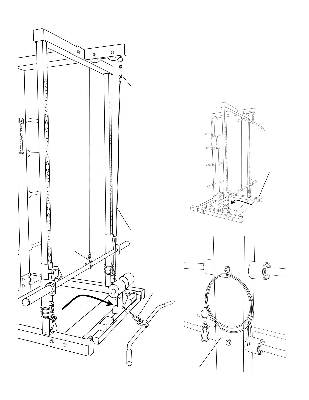
To set up the LOW PULLEY BAR for use, first swing the Low Pul-
ley bar into position and secure with BALL PIN. Next, attach LOW
PULLEY CABLE to ball end of upper pulley by first threading eye-
let end up through the LOW PULLEY BAR pulley and then secur-
ing with Carabineer.
Then, attach the LAT PULL BAR to the LOW PULLEY CABLE
using a Carabineer. Make sure the J-hook is properly seated un-
der the LIFT BAR and that the Safety hooks on LIFTING BAR are
located in upper position with lock out bolt in place prior to use.
J-Hook
BALL PIN
LOW PULLEY CABLE
Carabineer
When not in use, the LOW
PULLEY BAR swings into the
frame as shown. Leave the
BALL PIN in the mainframe to
avoid loss.
When not in use, you can use
the J-hook on the rear of the
mainframe SPINE for storage
as shown below.
LOW PULLEY CABLE
Table of contents
Other Ironmaster Fitness Equipment manuals

Ironmaster
Ironmaster Super Bench PRO Quick reference guide

Ironmaster
Ironmaster Cable Tower Attachment Quick setup guide

Ironmaster
Ironmaster Pec Dec Quick setup guide

Ironmaster
Ironmaster Spotting Stand User manual

Ironmaster
Ironmaster Leg Attachment for SuperBench Quick reference guide

Ironmaster
Ironmaster IM1500 Quick setup guide

Ironmaster
Ironmaster Quick-Lock Ultimate Training Vest User manual

Ironmaster
Ironmaster Quick-Lock Kettlebell User manual

Ironmaster
Ironmaster HYBRID BENCH PAD Quick reference guide

Ironmaster
Ironmaster Cable Tower Quick setup guide


