2
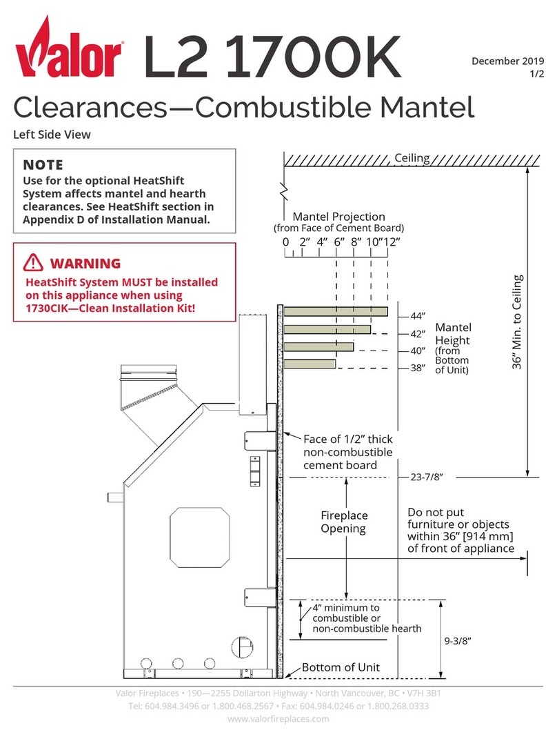
Step 4. The sight obstructor is installed with the curved edge down and
the bent edge towards the insert. Slide the tabs on the obstructor
into the slots (D in Figure 4)in the surround brackets. Refer to
the installation and operation manual to complete the installation
of the surround panels.
Step 5. The face has two hooks on each side that slide over and hang
on the surround brackets at (C in Figure 4). The face can be slid
slightly from side to side to center the face on the glass.
Step 6. If you have a gold or nickel face, be sure and clean the face with
a soft cloth and household glass cleaner prior to burning the
insert. Fingerprints left on the face while burning will usually
remain on the face permanently.
Printed in U.S.A. © 2014 IHP LLC
P/N 900149-00 Rev. NC 03/2014
IHP reserves the right to make changes at any time, without notice, in design, materials, specifications, prices and also to discontinue colors, styles and products. Consult your local distributor
for fireplace code information.
Innovative Hearth Products LLC
1508 Elm Hill Pike, Suite 108 • Nashville, TN 37210
INSTALLATION INSTRUCTIONS
Installation of the surround assembly is required prior to installing the
Arch Face and Inset Kits. For surround installation instructions, refer to
the installation and operation manual provided with the fireplace insert.
Step 1. Remove the face from the box (item #1 in Figure 1)and place
the face down making sure that the side with the studs are fac-
ing upwards. Be sure that the front of the face is lying on a soft
non-abrasive surface.
Step 2. Remove the insets from it’s box (item #2 in Figure 1). If you have
chosen a brushed nickel, black nickel or gold insets there will be
blue protective tape on the side that will be directed towards the
front of the appliance. If you have chosen black insets either side
can face the front of the face. Make sure the upper and lower inset
patterns are facing the same direction so they match up when
you are looking at the face.
Step 3. Place the arched insets holes over the studs along the top and
the bottom designated studs. There are seven studs on the top
of the face to mount the top inset, and there are four studs on the
bottom of the face to mount the bottom inset (See Figure 2 for
top stud locations and see Figure 3 for bottom stud locations).
The nuts to fasten the insets to the face can be found in the box
the face came in.
VERY IMPORTANT: SCREW THE NUTS ONTO THE STUDS “FINGER
TIGHT” ONLY. MAKE SURE THE FACE AND THE INSETS ARE NOT
BOWED BEFORE TIGHTENING. THEY MUST BE STRAIGHT BEFORE THE
INSETS ARE SECURED TO THE FACE. AFTER FINGER TIGHTENING THE
NUTS YOU MAY NOW SNUG THE NUTS SLIGHTLY. OVER-TIGHTENING
THE NUTS WILL RESULT IN DAMAGING THE STUDS AND THE FACE.
Figure 2
Figure 3
Studs at Top of Face
Studs at Bottom of Face
A
C
Figure 4
B
A = Speed nuts
B = Holes in the surround brackets - three on each side
C = Location where hooked brackets on face will hang
D = Slots in the bracket that the sight obstructor goes into
The face has two hooks on each side that slide over and hang on the
surround brackets at position C shown here. The face can slide slightly
from side to side to center the face on the glass.
D
Sight Obstructor (D)
B
NOTE: DIAGRAMS AND ILLUSTRATIONS ARE NOT TO SCALE.
fire-parts.com
