Irritrol SIS 120P Series Operating and maintenance manual

I.S.E. S.r.l.
Via Dell’artigianato 1/3
00065- Fiano Romano (RM)
Tel. 076540191-Fax 0765455386
www.irritrol.it
Maintenance and Operating Instructions
IRRITROL
Pop-up sprinkler with integrated valve
SIS 120P/SISF

2
I.S.E. S.r.l.
Via Dell’artigianato 1/3
00065- Fiano Romano (RM)
Tel. 076540191-Fax 0765455386
www.irritrol.it
Contents
1. General
2. Safety
3. Description
4. Assembly
5. Commissioning
6. Maintenance
7. Break-down and elimination of the defects
8. Spare parts list
1. General
We presume, that you are experienced in the field of irrigation. Therefore we have kept this
instruction as brief as possible, and have included such information only, which you must have
for the use of this product.
A guarantee can be accepted only, if the sprinkler has been operated in accordance with these
instructions, and if the defect occurs within the guarantee period.
1.1. Application
The sprinkler is used for the uniform distribution of the water. The water should be pre-
cleaned, and free of coarse and fibrous impurities.
Max. water temperature will be 50 degree C.
Max. ambient temperature will be 75 degree C.

3
I.S.E. S.r.l.
Via Dell’artigianato 1/3
00065- Fiano Romano (RM)
Tel. 076540191-Fax 0765455386
www.irritrol.it
2. Safety
These operation and safety instructions include basic remarks and hints for the assembly,
installation, operation, maintenance, inspection and repair. For this reason these instructions
must be read by the fitter, as well as by the customers authorised staff, prior to the installation
and commissioning.
Apart from the general safety instructions of this paragraph the special safety instructions
included in other paragraphs of these operating instructions have to be observed also.
2.1. Symbols of hints given in these operating instructions
The non-observance of the safety instructions mentioned in these operating instructions
can endanger persons, are
marked with the general danger symbol
especially.
Safety instructions which can endanger the sprinkler and its function, if not observed, are
specially marked and the word
has been inserted.
2.2. Dangers if the safety instructions are not observed
Non-observance of the safety instructions can endanger persons as well as the
environment and the sprinkler. Non-observance of the safety instructions can result in a
loss of all claims for indemnity.
ATTENTION

4
I.S.E. S.r.l.
Via Dell’artigianato 1/3
00065- Fiano Romano (RM)
Tel. 076540191-Fax 0765455386
www.irritrol.it
3. Description
Recommended operating pressure 5 to 6 bar
Permissible operating pressure 3 to 8 bar
The pressure at the sprinkler must not exceed 10 bar.
4. Assembly
(Sprinkler Valve in Head)
SIS120-FV Sprinkler to impact 360°
with sod cup for
natural turf
and valve in head
SIS120-PV Sprinkler to impact 30°-330° with valve in
head
SIS120-PGV Sprinkler to impact 30°-330° with valve in
head and artificial grass
Flush pipe work thoroughly before assembling
Threaded connection on the sprinkler is 1½“ female thread.
For sealing the thread, Teflon strip has to be used.
Installation of the sprinkler should occur according to the “Installation layout for PERROT
pop-up sprinkler LVZR 22 VAC“ (see next side).
To avoid burden pressure on the conduit pipe use in any rate a sprinkler swing joint.
It is recommended to assemble a gravel package, as shown in the installation layout.
The connection of the control cables is only allowed with approved watertight connections.
To screw the sprinkler on the swing joint hold on to the housing border or use a strap
wrench.
ATTENTION
ATTENTION

5
I.S.E. S.r.l.
Via Dell’artigianato 1/3
00065- Fiano Romano (RM)
Tel. 076540191-Fax 0765455386
www.irritrol.it
5. Commissioning / Winterise
5.1.1 Connection
Measurements:
5.1.2 Measurements
a) Check of electrical function :
Before the water supply to the valve is opened, the coil has to be triggered through a control
unit. Through an acoustic “click” on the coil, the correct electrical function can be
determined. (The click arise through attracting the relay armature.)
b) Open water supply to the sprinkler slowly. Probably the valve opens for a short time, but
after 30 sec. it should close on its own.
c) After opening the water supply and after the max. working / operation pressure is reached,
every seal has to be checked / examined.
d) Check valves and sprinkler for perfect function, when opening the valve manual.
e) While operation of the sprinkler, there is the possibility to adjust the desired irrigation
sector on the spring stop [14].
f) After the complete ventilation of the sprinkler the current supply to the coil must be
stopped, than the sprinkler has to close.
5.2
Winterise
Before beginning of the frost period the sprinkler has to be totally drained off.
Therefore there must be connected a powerful compressor on the network / main circuit.
Open the valve on the sprinkler until only air is coming out of the nozzle.
Sprinkler is equipped with a automatic drainage valve and could be winterised by gravity,
just by drainage the pipe.
After the drainage the solenoid has to be activated at least 5 times, so that remaining water
can be pressed out of the solenoid housing.
Sprinkler type SIS 120PV-PGV SIS120FV
Installation height 450 mm 660 mm
Rising height 99 mm 206 mm
Outer Ø housing 246 mm 246 mm
Outer Ø lid 180 mm 242 mm

6
I.S.E. S.r.l.
Via Dell’artigianato 1/3
00065- Fiano Romano (RM)
Tel. 076540191-Fax 0765455386
www.irritrol.it
picture 1

7
I.S.E. S.r.l.
Via Dell’artigianato 1/3
00065- Fiano Romano (RM)
Tel. 076540191-Fax 0765455386
www.irritrol.it
6. Maintenance
Clean interior space of the sprinkler with a industrial type vacuum cleaner or a similar device.
Clean / relieve sprinkler housing from overgrown grass. This work should be done
conveniently before commissioning in spring.
7. Break-down and elimination of the defects
7.1 Disassembly
Unscrew the screws [3] from the lid [2] Take off lid [2] and securing bracket [4].
Unscrew the screws [6] and pull out the sprinkler insert [5].
The sheet metal housing with edge [1] can be pulled out for repair or inspection on the
electrical parts in case of the pop-up sprinkler types LVZR 22-2VDC/VAC/VDE
Disassembly valve piston
Before the following mentioned work is carried out, it must be sure that
the sprinkler is depressurised.
The solenoid [19] can be screwed out with or without the solenoid adapter [18] by
turning anti clockwise. The filter has to be pulled out for cleaning.
Pull out the retaining circlip [9] with the installation hook [33]. Push the installation
hook from the left (arrow) into the bore and turn the installation hook to the left
whilst pulling it out again.
Screw the valve lifter [32] into the valve insert [12]. Loosen the valve insert [12] by
applying slight blows with the sleeve around the lifting tool. Pull out the valve insert.

8
I.S.E. S.r.l.
Via Dell’artigianato 1/3
00065- Fiano Romano (RM)
Tel. 076540191-Fax 0765455386
www.irritrol.it
7.2 Assembling of the sprinkler
7.2.1 Flush sprinkler
In case that the valve contains soil particles, the sprinkler has to be flushed before
assembling.
Assemble flushing equipment [31] in the sprinkler housing (see picture 2) and open
water supply. Connect hose on flushing equipment, so that water can be derived.
picture 2
7.2.2 Assembly of valve
Screw the valve insert [12] with the stainless steel [10] onto the valve lifter [32]. The
chambered surface of the stainless steel must point to the valve insert [12]. The valve
insert must be greased slightly at the sealing beads [11] and [13] before it is pushed
back into the housing.
The control drilling between the two sealing beads [13] must point towards the
manual control device or ventilating screw during assembly. (±3 degree or ±5mm at
the diameter of the sealing beads [11] ). Push the valve insert [12] into the housing
accompanied by slight hits with the sleeve around the valve lifting tool.
Replace the retaining circlip [9] into the groove by using the pliers [30]. Make sure
that the circlip fits properly! If necessary push with the taper at the valve lifter [32]
towards the outside.
7.2.3 Sprinkler assembly
Place the sprinkler insert with its guide pins [8] in any small groove. Press the flange
[7] and fasten with screws.
Fit housing lid [2] with securing bracket [4] and screws [3].
The sprinkler is now completely assembled. Now the function can be checked as
described under point 5.1.
[31]

9
I.S.E. S.r.l.
Via Dell’artigianato 1/3
00065- Fiano Romano (RM)
Tel. 076540191-Fax 0765455386
www.irritrol.it
7.3 Break-down and elimination of the defects
Break down Cause / reason Elimination
Valve opens / closes only
manual not by electrical, Coil or coil seat is dirty Remove coil and clean it,
see point 7.1.
Control signal Supply voltage is too low
(24VAC/DC) Check supply voltage and
cable connections
Coil is broken Check coil resistance
(must be appr. ca. 30Ω)
Plunger in coil is seated Change coil
Valve does not open, even
not manual Seal of valve insert is
defect Change valve insert (see
point 7.1.)
Exit for control water on
cylinder of the valve is
blocked
Disassembly control pipe
out off connection and
blow through backwards
Valve does not close, even
not manual, Filter for control water is
dirty Disassembly valve insert
and clean filter or change it
(see point 7.1.)
Leakage in the control
water path Check all connections,
control pipe and pressure
regulators units for
leakage’s and eliminate
them.
The pressure on the
sprinkler nozzle is too low. Valve is blocked Disassembly valve and
flush pipes (see point 7.1)
7.3.1 How to check sprinklers, which do not open
Check solenoid in or at the controller for efficient operation.
Engage valve and check at the relief exit of the controller for a brief water splash
to come out
Exchange solenoid at the controller only when there is no pressure in the line
7.3.2 How to check sprinklers, which doesn’t close
Control line has not been ventilated completely.
Foreign particles are blocking the valve
There is a leak in the hydraulic system.
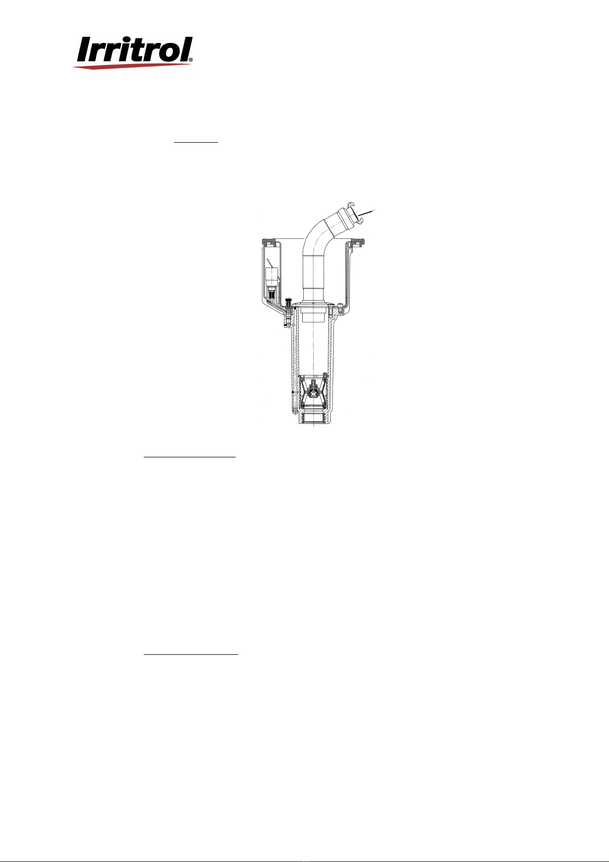
The retaining circlip [9] on top of the valve is not fitted correctly and the valve has
been pushed out of it's seat by the operating pressure.
Check the outlet of the solenoid valve for correct functioning. To implement this,
disconnect the control line. The valve at the controller is normally open (without
current).
Subject to change without prior notice.

10
I.S.E. S.r.l.
Via Dell’artigianato 1/3
00065- Fiano Romano (RM)
Tel. 076540191-Fax 0765455386
www.irritrol.it
Attached
SIS 120F/ SIS 120P
without valve

11
I.S.E. S.r.l.
Via Dell’artigianato 1/3
00065- Fiano Romano (RM)
Tel. 076540191-Fax 0765455386
www.irritrol.it
Contents
1. Description
2. Installation
3. Commissioning
4. Adjustments
5. Maintenance / Cleaning / Repair
6. Preparation for winter time
7. Troubleshooting + Solutions
8. Disassembly and assembly of sprinklers
1. Description
Recommended operating pressure 5 to 6 bar
Permissible operating pressure 3 to 8 bar
The pressure at the sprinkler must not exceed 10 bar.
SIS120-P Sprinkler to impact 30°-330°
SIS120-PG Sprinkler to impact 30°-330°with
artificial grass
SIS120-F Sprinkler to impact 360°with sod
cup for natural turf
ATTENTION

12
I.S.E. S.r.l.
Via Dell’artigianato 1/3
00065- Fiano Romano (RM)
Tel. 076540191-Fax 0765455386
www.irritrol.it
2. Installation
Dimension
When installation to the public water supply system, you must pay attention to the
regulations of the water utility respectively guideline of the DVGW (Deutscher
Verein der Gas- und Wasserfachmänner e.V.).
On stony ground, pipes are to be laid in a sand bed. The sand bed should surround the
pipe everywhere 10 cm.
It is necessary that the installation of the pop-up sprinkler is in the same level as the
ground.
Under each sprinkler there must be, a gravel packing of 3 – 10 buckets of gravel,
grading approximately 32. A perfect drainage of the sprinkler housing is very
important.
Pop-up sprinkler
Main pipe
Coarse gravel
Swing joint
PE-connection
T-piece
Flush the pipes proper before installation of the sprinklers
3. Commissioning
Pipes must always be filled slowly, that means you must open the gate valve gradual, under
observance of the assigned operating pressure. Despite of a thoroughly flushing it may happen
that the sprinkler nozzle is blocked. To clean the nozzle you must turn off the nozzle and flush
the sprinkler. To unscrew the nozzle you must put a block under the lid or take off the cover.
(Use socket spanner)
Sprinkler type SIS 120P-PG SIS 120F
Installation height 370 mm 573 mm
Rising height 98 mm 205 mm
Outer Ø housing 246 mm 246 mm
Outer Ø lid 180 mm 242 mm

13
I.S.E. S.r.l.
Via Dell’artigianato 1/3
00065- Fiano Romano (RM)
Tel. 076540191-Fax 0765455386
www.irritrol.it
4. Adjustments
4.1 Sectors
The sectors of the reference part circle of sprinklers are adjusted by pushing the spring stop
at the end, which expand the spring. You achieve a crude adjustment before installation,
the fine adjustment should be done on the working sprinkler.
4.2 Casting range
The casting range is regulated through the application of different nozzles and pressures.
(Further information see catalogue)
4.3 Jet deflector screw (type SIS120P no adjustment available)
The jet deflector screw is for adjustment of the near irrigation around the sprinkler. If you
screw in further the screw in the water jet, the „rainfall“ consistency around the sprinkler
increases, the casting range decreases. If you unscrew the interruption screw the irrigation
around the sprinkler decreases and the casting range increases.
5. Maintenance / Cleaning / Repair
To clean or suction the housing you must lift the sprinkler by hand or remove the cover
from time to time.
Examine function of gravel package
In case that the sprinkler insert or nozzle head is dirty, only clean it with water.
Do not use lubricants or grease, other wise the gliding plate in the sprinkler might be
damaged!!!
Please dismount defect parts immediately and repair them or send them to repair.
6. Preparation for winter time
Before winter the pipe system and the pumping station are to be drained. The drainage valve
must be open until the next in commissioning.
By sprinklers with a stop valve (H), the water above the stop valve cannot discharge itself.
Because of that reason the sprinkler insert of the installation are to be lift on the cover ( e.g. for
winterising). When the sprinkler insert are lift, the water can flows out off the guiding housing
and air can enter into the conductions.
Therefore it is the best to put a piece of wood with approximately 2 cm between cover and
housing until the installation is empty.

14
I.S.E. S.r.l.
Via Dell’artigianato 1/3
00065- Fiano Romano (RM)
Tel. 076540191-Fax 0765455386
www.irritrol.it
7. Troubleshooting + Solutions
Attention !!!
Before above-mentioned works are executed, it must be ensure
that the valve is pressure-less.
In case of less casting range of some sprinklers it might be garbage in the filter.
Then you must dismount the sprinkler insert and clean the filter.
Flushing the pipe
Only with flushing insert, otherwise the water which flows back can take garbage with it in the
housing and can than enter to the pipe system.
8. Disassembly and assembly of sprinklers
That work can be done with help of standard tools.
Disassembly
Unscrew slot screws in the cover.
Remove screw / nut and pull out sprinkler insert
Assembly
Tighten sprinkler insert with screw / nut
Mount cover with screws and retainer for cover
Subject to change without prior notice.
Halteventil
Stopva
lve
Gehäuse
housing
Holzstück
peace of wood
Deckel
cover
This manual suits for next models
4
Table of contents
Other Irritrol Irrigation System manuals