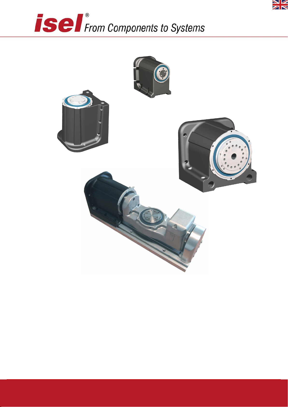
RDH-XS, RDH-S, RDH-M, DSH-S
6 / 44 April 2019
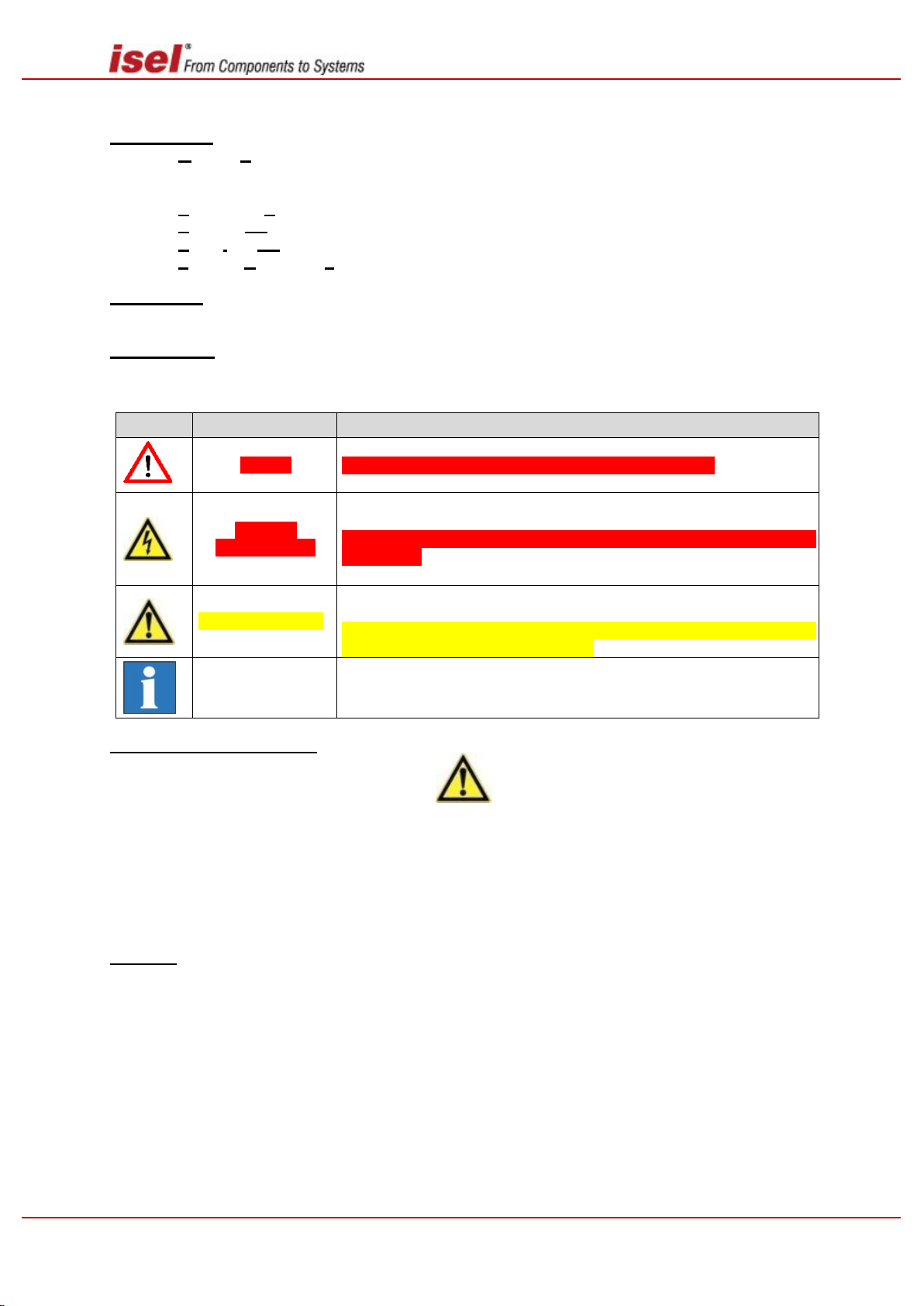
1.1 Safety guidelines
The following guidelines on safety and danger are intended to protect you, third parties
and the product. It is essential that you follow them.
Operating environment
The surrounding medium must not have a corrosive effect on aluminium alloys, stainless steels
(1.4305) or ABS plastics.
The product has achieved Protection Type IP65 if no corrosion has been caused on the surface
of the radial shaft seal by the operating environment.
When moving the product from cold to warm conditions, allow the product to adjust to the change
in temperature for a few hours, to avoid possible damage from condensation.
Do not install the product near devices which generate powerful magnetic fields. This could
disturb some products main functions.
Avoid environments exposed to direct solar radiation, considerable heat, cold, humidity or mois-
ture.
Power supply (only applies to products with multiphase motors, brushed DC/brushless DC or
AC servo motors and a suitable motor output stage/controller)
Only connect the power supply of the multiphase motor/servo motor output stage iMD10/iMD20,
the link to the servo motor output stage iMD40 (terminals L, N, PE) or the single-axis or multi-
axis controller (e.g. iMC-P/iMC-S8, MC-1 series, iPU series…) to an earthed mains socket with
a mains voltage of 230 V AC/50…60 Hz (1-phase AC power supply).
It is preferable to use for the final stage of the mulitphase motor or the final stage of the
iMD10/iMD20 servomotor the original power supply recommended by isel Germany AG (primary
power supply: 230V AC, secondary: 48V DC). Using a different, inappropriate power supply
renders the warranty null and void. In addition, using an inappropriate power supply entails risks
caused by electric current, such as electric shock, fire or short circuits!
If you notice faults, activate the EMERGENCY STOP button on the (single axis) controller, the
CNC operating panel/CNC console, the control panel/control cabinet or a handheld device. Ac-
tivating the EMERGENCY STOP button interrupts the power supply to the motor output stage.
If the power supply used is damaged you must not operate it. Have a qualified technician check
and if necessary repair the product.
The rotary unit
For safety reasons you must not convert and/or modify the rotary unit on your own.
In operation, the rotary unit must not be concealed by supplies (electricity or compressed air),
objects (e.g. tools) or tarpaulins, packaging or other materials etc. (e.g. clothing), because this
can lead to mechanical damage or heat obstruction and sometimes fire.
If using a single-axis/multi-axis controller to control a linear unit (equipped with an AC, brushed
DC (BDC) or a brushless DC (BLDC) servo motor), you need to ensure that the controller or
motor output stage used (in a control cabinet or on a mounting rack) is placed in a well-ventilated
environment.