ISHIDA IL-2000SA User manual

IL-2000SA
SERVICE MANUAL
First Edition, November 2007
Manual No. RS-61021-11
CAUTION
READ AND UNDERSTAND THIS MANUAL
•Thoroughly read and understand this manual before installing, operating, inspecting, or
servicing the machine.
•Keep this manual in a safe place where you can refer to it whenever necessary.
DISCONTINUED
107743

© ISHIDA CO., LTD., 2007
©2007 ISHIDA Co., Ltd.
COPYRIGHT AND COPY PERMISSION
This manual shall not be copied without permission.
This manual is protected by copyright and is intended solely for use in conjunction with the machine.
Please notify us before copying or reproducing this manual in any manner, for any other purpose.
DISCONTINUED

SAFETY PRECAUTIONS
IL-2000SA Service Manual i
SAFETY PRECAUTIONS
Those who handle the machine must be aware of the hazards involved. These dangers may not be
obvious, so it is imperative to follow the instructions detailed in this manual when installing, operating,
inspecting, or servicing the machine. Therefore, we recommend that you thoroughly read and
understand this manual before installing, operating, inspecting, or servicing the machine.
ISHIDA is not liable for any damage, loss or injury that results from incorrect handling, insufficient
caution, unauthorized modifications to the machine, or failure to follow the instructions contained in
this manual.
In the recent weighing industry, the latent hazards involved with handling the machine have increased
due to new materials, new processing methods, and higher processing speeds, and it is impossible to
predict all of the possible dangers.
Likewise, there are far too many operations which cannot or should not be performed to fully describe
all of them in the manual. Please assume that any operation not specifically described in this manual
should never be performed.
Safety countermeasures should be carefully considered and implemented before performing any
installation, operation, inspection, or maintenance procedure not specifically described in this manual
or indicated on the machine itself.
Battery Disposal:
When replacing a battery, make sure that it is the same model or an equivalent. Dispose of used
batteries according to the local regulations.
When replacing the board, follow local regulation on its disposal because the board contains lithium
batteries.
DISCONTINUED

MEANINGS OF SIGNAL WORDS
ii IL-2000SA User’s Manual
MEANINGS OF SIGNAL WORDS
This machine is manufactured for use according to proper procedures by a qualified person and only
for the purposes described in this manual. The following conventions are used to indicate and classify
precautions depending on the level of danger, or seriousness of potential injury. Always heed the
information provided in this manual. Failure to heed precautions can result in personal injury or
property damage.
The following signal words are used in this manual.
Indicates a potentially hazardous situation which, if not avoided, will result in
minor or moderate injury, or may result in serious injury or death. Additionally,
there may be significant property damage
Indicates a potentially hazardous situation where, if not avoided, may result
in minor or moderate injury or in property damage.
Indicates a reminder or emphasis of information.
DISCONTINUED

TABLE OF CONTENTS
IL-2000SA Service Manual iii
TABLE OF CONTENTS
Chapter 1 OUTLINE ..........................................................................1-1
1.1 OUTLINE.................................................................................................1-1
1.2 SPECIFICATIONS...................................................................................1-1
1.3 FEATURE ................................................................................................1-2
Chapter 2 INSTALLATION................................................................2-1
2.1 OUTER DIMENSIONS.............................................................................2-1
2.2 CONTENTS OF THE PACKAGE............................................................2-2
1. Items Required at the Delivery ...................................................................2-2
2.3 INSTALLATION.......................................................................................2-3
1. Installation Conditions ..................................................................................2-3
2. Connecting Options......................................................................................2-3
3. Power Supply ...............................................................................................2-3
2.4 SETUP.....................................................................................................2-4
1. Setup Flow ...................................................................................................2-4
2. Software Setup.............................................................................................2-4
3. Handling Description ....................................................................................2-4
Chapter 3 TEST MODE.....................................................................3-1
3.1 START UP OF TEST MODE ...................................................................3-1
3.2 TEST MODE HIERARCHICAL CHART..................................................3-2
3.3 KEY CHECK............................................................................................3-3
1. Numeric Key Check......................................................................................3-3
2. Touch Panel Adjustment...............................................................................3-4
3.4 ALL DIAGNOSIS.....................................................................................3-5
3.5 MEMORY CLEAR....................................................................................3-6
3.6 DISPLAY CHECK....................................................................................3-7
3.7 PRINTER ADJUSTMENT........................................................................3-8
3.8 ROM VERSION .....................................................................................3-12
3.9 COMMUNICATION CHECK..................................................................3-13
3.10 OPTION CHECK ...................................................................................3-15
3.11 MEMORY DATA.....................................................................................3-16
3.12 DATE SET.............................................................................................3-17
Chapter 4 SYSTEM SETTING MENU...............................................4-1
4.1 START UP OF SYSTEM SETTING MENU.............................................4-1
4.2 HIERARCHICAL CHART OF SYSTEM SETTING MENU......................4-2
4.3 SALES MODE SETTING.........................................................................4-3
4.4 MACHINE NUMBER SETTING...............................................................4-4
4.5 HOLD DATA SETTING............................................................................4-5
DISCONTINUED

TABLE OF CONTENTS
iv IL-2000SA Service Manual
4.6 AUTOMATIC UPDATE SETTING ...........................................................4-7
4.7 OPTION SETTING...................................................................................4-8
4.8 CASSETTE SETTING...........................................................................4-10
4.9 LABEL SETTING ..................................................................................4-12
4.10 FORMAT SETTING...............................................................................4-14
4.11 UNIT SETTING......................................................................................4-15
4.12 PRINT SETTING....................................................................................4-15
4.13 FILE CHECK .........................................................................................4-16
4.14 FILE SAVE/LOAD .................................................................................4-17
4.15 BARCODE CHECK...............................................................................4-18
Chapter 5 SET UP MENU .................................................................5-1
5.1 START-UP OF SET UP MENU................................................................5-1
5.2 SET UP MENU 1 .....................................................................................5-2
1. Date/Time Setting.........................................................................................5-2
2. Expiry Date Setting.......................................................................................5-3
3. Password Setting..........................................................................................5-3
4. Preset...........................................................................................................5-4
5. Reference Data Setting................................................................................5-5
6. Total Setting..................................................................................................5-6
7. Report Setting ..............................................................................................5-6
8. Cassette Link Setting....................................................................................5-7
9. Date Display Setting.....................................................................................5-8
10. Key Image Select .........................................................................................5-8
5.3 SET UP MENU 2 .....................................................................................5-9
1. System Data Setting...................................................................................5-10
2. Barcode Setting..........................................................................................5-11
3. Item Code Setting.......................................................................................5-11
4. PLU Update................................................................................................5-12
5. Serial Number Setting ................................................................................5-12
6. Book Setting...............................................................................................5-13
7. Memory Card Setting..................................................................................5-13
8. Master Initial Value Setting.........................................................................5-14
Chapter 6 HARDWARE CONFIGURATION......................................6-1
6.1 MECHANICAL COMPONENTS..............................................................6-1
1. Main Unit......................................................................................................6-1
2. Printer Unit ...................................................................................................6-2
3. Display Unit..................................................................................................6-3
6.2 ELECTRICITY .........................................................................................6-4
1. Electric Block................................................................................................6-4
2. Board Setting................................................................................................6-5
DISCONTINUED

Chapter 1 OUTLINE
IL-2000SA Service Manual 1-1
CHAPTER
OUTLINE
1.1 OUTLINE
The IL-2000SA is a label printer that has the same functions as the SR-2000αexcept for the weighing
unit. The main board, printer board, and cassette of the IL-2000SA are common to the SR-2000α.
1.2 SPECIFICATIONS
Items Descriptions
Model IL-2000SA
Operating conditions Temperature: 32 to 104°F (0 to 40°C)
Humidity: 20 to 85% (no condensation)
Outer dimensions 8.9 (W) ¯14.7(D) ¯12.9-14.2 (H) inch
225 (W) x 370 (D) x 330-360 (H) mm
Operator display 7.7 inch STN LCD with back light, 640 ¯480 dots
Preset keys 3960: 40 x 99 pages
Memory capacity Standard: 34 MB
Communications TCP/IP 10/100 Base T Ethernet
Interface Two PCMCIA slots
Printing method Direct thermal method
Thermal print head 3 inches (76/mm)
Printing speed 4” (100 mm) per second
Label size Label width: 1.5” - 3.1” (30 mm to 80 mm)
Label length: 1.2” – 7.9” (30 mm to 200 mm)
Label roll Inside diameter: 1.6” (40 mm)
Outside diameter: 3.9” (100 mm)
Label backing paper Width: Up to 3.3” (84 mm)
Number of label
cassettes 7 cassettes
Weight: 20.7 lb (9.4 kg)
Power supply AC 110 to 120 V, 60 Hz, 4A
Warranty One-year limited warranty
Weight 9.4 kg
Power supply Canada: AC110 to 120[V] 60[Hz] 4[A]
New Zealand: 220 to 240[V] 50/60[Hz] 2[A]
1
DISCONTINUED
Chapter 1 OUTLINE
1-2 IL-2000SA Service Manual
1.3 FEATURE
¡Mechanical Components
(1) The machine height is lowered by sliding the thermal head forward.
The height is further lowered by adopting the prismatic reflection for the label sensor.
(2) The label adhesion is suppressed by applying the grain processing.
(3) The 3-inch wide label can be printed.
¡Electric Components
(1) 7.7-inch color liquid crystal is adopted for the operator display. (640 dots °480 dots)
(2) 7.7-inch touch panel is adopted for operation panel.
(3) 3-inch thermal head is adopted.
IL-2000SA (3 inches)
(4) Printing speed becomes faster.
IL-2000SA (100 mm/second)
(5) 3-inch wide label can be printed.
IL-2000SA (3-inch)
The print effective width is as follows:
IL-2000SA (76 mm)
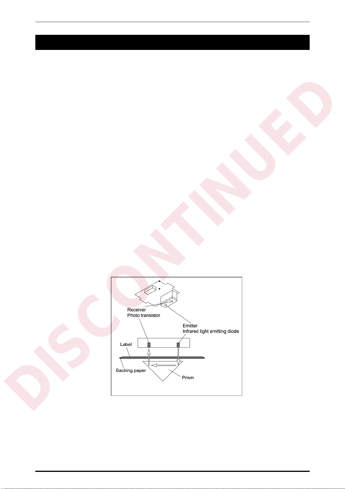
(6) The mechanism is simplified by adopting the prism for the label sensor (transparent type), and
the machine height can be lowered.
(7) The micro step drive is adopted for the label feeding motor, therefore, smoother rotation
becomes possible.
IL-2000SA (micro step drive)
(8) Modular connector is adopted for the I2NET communication.
L-2000SA (modular)
DISCONTINUED

Chapter 1 OUTLINE
IL-2000SA Service Manual 1-3
(9) The RS-232C port for general-purpose interlock is installed.
IL-2000SA (RS-232C port)
(10) The card slot (PCMCIA) port is provided.
IL-2000SA (PCMCIA port)
(11) CompactFlash/flash ROM is adopted for the program storage.
IL-2000SA (CompactFlash)
CompactFlash (32 Mbyte)..................OS + Application program
Flash ROM (1 Mbyte).........................Boot program
DISCONTINUED

DISCONTINUED
Table of contents


