manuals.online logo
Brands
  1. Home
  2. •
  3. Brands
  4. •
  5. Mitsubishi
  6. •
  7. Touch Terminal
  8. •
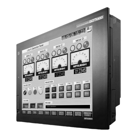
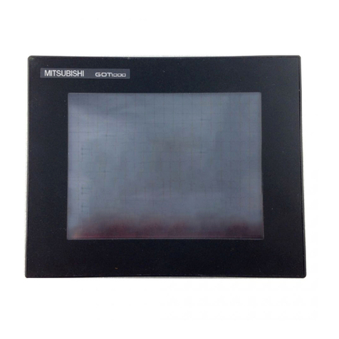
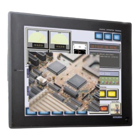
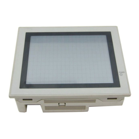
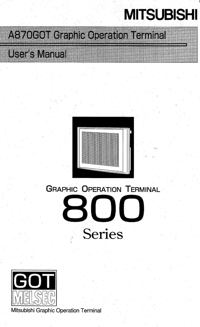
  9. Mitsubishi GOT MELSEC 800 Series User manual

Mitsubishi GOT MELSEC 800 Series User manual

Series
MitsubishiGraphic OperatiorlTerminal
@
SAFEW
PRECAUTIONS
8
(Readthese precautionsbeforeusing.)
VVhen using Mitsubishiequipment, thoroughly readthis manualandthe associatedmanualsintroducedin
this manual. Also pay careful attentionto safety and handlethe moduleproperly.
These precautions apply only to Mitsubishiequipment. Refer to the CPU module use's manual for a de-
scription of the PC system safety precautions.
These
Q
SAFETY PRECAUTIONS
8
classifythe safety precautionsintotwo categories: "DANGER" and
"CAUTION".
Procedureswhich may leadto a dangerous condition and cause death
I
or serious injury if notcarried out properly.
I
I
Procedureswhich may leadto
a
dangerouscondition and cause superfi-
I
I
cia1to medium injury, or physicaldamageonly, if notcarried out properly.
I
L------------------------------------J
I
Depending on circumstances, procedures indicated by
A
CAUTION
may'also be linked to serious
!
results. Inany case,
it
isimportant to followthe directions for usage.
Store this manual in a safe place so that you can take itout and read it whenever necessary.Always
forward
it
tothe end user.
[DESIGN
PRECAUTIONS]
O
A malfunction inthe GOT mainmodulemay keepthe output ON or OFF. Add a circuit to exter-
nally monitorthe output which could lead to a seriousaccident.
An accident may occur byfalse output or malfunction.
Q
If a communicationerror (includingbyadisconnectedcable)occurs whilethe monitoris running
onthe GOT, the communicationbetweenthe GOT andthe master station is interrupted, andthe
GOT stops running.
Fora system configurationusingaGOT, designthe system suchthat the crucialswitchingtothe
system isperformed bythe equipmentotherthan the GOT with the assumptionthat acommuni-
cation errorcould occur inthe GOT.
An accident may occur byfalse output or malfunction.
[DESIGN
PRECAUTIONS]
@
DANGER
Read Chapter
5
"Data Link ProcessingTime" inthe Master ModuleUser's Manual carefully re-
gardingthe statusof each stationwhen the PC CPU operation isstopped or the data link be-
comesa communicationerror.
Also, configurean interlockingcircuit inthe sequence programusingthe communicationstatus
information(SB and SW) so that the overallsystem isalways maintained.
An accidentmay occur byfalse output or malfunction.
Receiveddatafrom masteror localdatalinkfaulty station.
@
Remoteinput
(RX)
and remoteoutput
This varies dependingon the setting of the module's condition setting switch and input
data(SW4) of the data linkfaulty station.
OFF
:
Clear (all off)
ON
:
Keepsthe data rightbeforethe error occurrence.
@
Remoteregisters(RWw and RWr)
The data right beforethe error iskept regardlessof the SW4 setting.
Regardlessthetouch-switchfunction is set or not, when multipletouchswitches(twoplacesor
more) are pressedsimultaneously
as
showninthe followingdiagram, the
GOT
isdesignedto
execute
a
pre-definedoperationof thetouchswitch if atouch switchfunction is definedat the
fourth vertex of the rectangle.
When two touch swiches are pressed:
When three touch swiches are pressed: When four touch swiches are pressed: When four touch swiches are pressed:
"
:
Indicatestouches position.
0
:
Indicatesthe switch recognized
by
the
GOT.
#
:
Indicates
a
touch switch.
:
Indicatesthe touch switch that executesthe set action.
When multipletouchswitchesare pressedsimultaneouslyundertheconditionsdescribedabove,
makesurethatthesystem works safelybycarefullyconsideringthe locationof eachtouchswitch
function and addingan interlockcircuittothewrite device usinga sequence program,etc.
A malfunctionmight causea breakdown, accident,or damagetothe machine.
[DESIGN
PRECAUTIONS]
O
Do not bunch the communication cableswith the main circuit or power wires, or installthem
closeto eachother. They should be installed
100
mm
(3.9
inch)or morefrom each other, Failure
to do so may resultin noisethat would cause malfunctioning.
1
[INSTALMTBON PRECAUTIONS]
8
Makesure toswitchall phasesof the extemal GOT's power supply off before installingor remov-
ingthe GOT main moduletolfrom the base.
If you do not switch off the external power supply,
it
will cause failure or malfunction of the
module.
Q
Makesuretoswitchall phasesof the extemalGOT'spower supply off beforemountingor remov-
ingthe optional moduletolfrom the GOT main module.
If you do not switch off the external power supply,
it
will cause failure or malfunction of the
module.
8
Make sure to switch all phasesof the external GOT and PC CPU side power supplyoff before
connectingthe communication cabletothe GOT main module.
I
If you do not switch off the external power supply,
it
will cause failure or malfunction of the
I
L
module.
[BIVSTALMTION PRECAUTIONS]
Q
Usethe GOT inthe environment given inthe general specifications of the GOT User's Manual.
Usingthe GOT outsidethe rangeof the generalspecificationsmay result inelectric shock, fire or
malfunctioning, or may damageor degrade the module.
63
Tightenthe installationscrewsfor installingthe GOT mainmoduletothe basewithinthe rangeof
specifiedtorque.
Ifthe installationscrews are loose, itmay resultinfallout, short circuits, or malfunctions.
Tighteningthe installationscrewes too far may causedamagestothe screws and/orthe module,
resultinginfallout, short circuits, or malfunctions.
WIRING
PRECAUTIONS]
8
Makesuretoswitchall phasesof the externalGOT's powersupply off beforebegingwiringwork.
If you do not switch off the externalpowersupply,
it
will cause electric shock, malfunction, or
I
I
damageto the module.
WIRING PRECAUTIONS]
CAUTION
The FG and LG terminals should always be grounded using the class-3 or higher grounding
designedspeciallyfor the GOT. Failureto groundthese terminals may cause electric shock or
malfunctions.
@
When wiringthe GOT, check the ratedvoltage and terminal layoutof the wiring, and makesure
the wiring is done correctly. Connecting a power supplythat differsfrom the rated voltage or
wiring itincorrectlymay causefire or failure.
Tightenthe GOT's terminalscrews withintherangeof specifiedtorque. Iftheterminalscrewsare
loose, itmay result infallout, short circuits, or malfunctions. Tighteningthe terminalscrewstoo
far may cause damages to the screwsand/or the module, resultinginfallout, short circuits, or
malfunctions.
When wiringthe GOT, becareful that foreign objects, such as chips from the braidedshieldand
wiringscraps, don't get caughtinthe GOT main moduleandthe optional module.
These can cause fire, failure or malfunctions.
[PRECAUTIONS WHEN PERFORMINGTHE TEST OPERATION]
Readthe manual carefullyand fully understandthe operationbeforethe test operation(ONIOFF
of bitdevices, modifyingcurrentvalue of aword device,modifyingtimerlcountersetting, modify-
ingthe current value, or modifyingthe current value of a buffer memory) of the user created
monitorscreen.
Inaddition, never modifydata in atest operationtoadevicewhich performsa crucial operation
tothesystem.
Itmay cause an accidentbyfalse output or malfunction.
[STARTING AND MAINTENANCEPRECAUTIONS]
Do nottouchthe terminalswhile the powerison. Doingso may causeelectricshockor malfunc-
tion.
Do notchangethe switch settingwhilethe power ison. Itmay causefailureor malfunction.
Make sure to switch all phases of the external GOT's power supply off before cleaning or re-
tighteningterminal screws. Ifyou do notswitchoff the external powersupply, itwill causeelec-
tric shock. Ifthe terminal screwsare loose, itmay result infallout, short circuits, or malfunctions.
Tightening the terminal screws too far may cause damages to the screws and/or the module,
resultinginfallout, short circuits, or malfunctions.
[STARTING
AND
MAINTENANCE
PWEMUTIONS]
4B
Never disassembleor modifythe GOT mainmoduleandoptional module. This may causefailure,
malfunctions, injury,and/or fire.
(D
Don't touch the conductive parts and electronic parts of the GOT main module and optional
module.This may cause the moduleto malfunctionor failure.
4B
Bacausethey are madeof resin, don't dropor given astrongshocktothe GOT mainmoduleand
optional module.
This may causefailure.
[DIISPOSAL
PRECAUTIONS]
CAUTION
(B
When disposing of this product, treat
it
as industrialwaste.
[PRECAUTIONS
WHEN
WEPMCPNG
THE
BACMLIGHTJ
cB
Make sure to switch all phases of the external GOT's power supply off before replacingthe
backlight, and first remove the GOT main module from the panel. If you do not switch off the
external power supply,
it
will cause electric shock. If left in the panel, the GOT could fall and
cause an injury.
-
CAUTION
(9
Perform replacement of the backlight at a placewhere no other machines exist in order topre-
vent troubles in caseafixed screw of the backlightor GOT drops.
If such screw is dropped,
it
may cause damage to the machineor an accident.
@
Do not touch the GOT's circuit boardor electronic parts when replacing the backlight.
Doingso could cause failure or malfunction.
@
Tighten the backlight fixed screws within the rangeof specified torque. If the fixed screws are
loose,
it
may result infallout, short circuits, or malfunctions.
Tightening the fixed screwstoo far may result in damages, short circuits, or malfunctions of the
screw and/or module.
(8
Do not pull the cable connector of the backlight when replacing the backlight. Doing so could
cause damage or failure of the backlight.
[PRECAUTIONSWHEN DISPOSING
THE
BACKLIGHT'J
CAUTION
When disposingthe backlight, treat it
as
industrialwaste.
Revisions
This manualdoes not implyguarantee or implementationrightfor industrialownershipor implementationof
other rights. MitsubishiElectric Corporation is not responsiblefor industrialownershipproblems caused by
use of the contents of this manual.
L
0
1997
Mitsubishi Electric Corporation
Introduction
Thank you for purchasingthe MitsubishiGraphic Operation Terminal
.
Before usingthe equipment. please read this manual carefully to developfull familiarity with the functions and
performanceof the graphic operationterminalyou have purchased. so as to ensure correct use
.
Pleaseforward a copy of this manualtothe end user
.
Contents
1
.
OVERVIEW
1- 1
to
1
-13
.
1
.
1 Supplied Parts
......................................................................................................................
1 1
1.2 About A852GOT Compatible SoftwarePackages
..................................................................
1
-
2
1
.
3 Software PackageVersion Checking Method
..........................................................................
1
-
2
.............................................
1
.
4 DeviceSpecificationMethodWhen Creatingthe MonitorScreen
1
-
3
1.5 Features
..................................................................................................................................
I
-
4
1
.
6 Structureand Guidetothe Use of This Manual
.......................................................................
1
-
7
1
.
7 Abbreviations andTerms Used inThis Manual
.........................................................................
1
-
9
1.8 PrecautionsWhen Installingthe ROM-BIOS/OS
......................................................................
1-1
0
1
.
9
ProcedureOverview Beforethe Operation
...............................................................................
1-11
1
.
10 A852GOT's Monitor Functions
...............................................................................................
1
-12
2
.
SYSTEM CONFIGURATION
............................................................
2.1 System ConfigurationWhen Creating MonitorScreens
2-
1
.................
2.2 System Configuration Usedfor DataTransfer. Debugging.and Document Creation 2- 2
2.2.1 Systemconfigurtation
.................................................................................................
2-
2
2.2.2 RS-232Ccables used for datatransfer
.......................................................................
2- 2
2.3 NecessaryEquipment for A852GOT
.........................................................................................
2-
3
.....................................................................................
2.4 Total Configurationof CC-LinkSystem 2- 4
2.5 Twisted PairCable Specification
...............................................................................................
2- 5
2.6 Applicable CPU
........................................................................................................................
2-
6
2.7 List of ConfigurationEquipment
................................................................................................
2-
7
3
.
SPECIFICATION
3-1t03-3
3.1
General Specifications
.............................................................................................................
3- 1
3.2 PerformanceSpecifications
......................................................................................................
3- 2
4
.
MONITOR SPECIFICATION
4-
1
t04-28
.....................................................................................................................
4.1 Monitor Overview
4-
1
4.2
1/O
Signalstothe Master Module
.............................................................................................
4- 5
4.2.1 List of I/O signals
.........................................................................................................
4-
5
4.2.2 Details of the I/O signals
..............................................................................................
4-
6
4.3 RemoteRegister Allocation
......................................................................................................
4- 8
4.4 CommandList for the DedicatedCommand MonitorMethod
..............................................
4-
9
4.5 Details of EachCommand
.......................................................................................................
4-1
0
4.5.1 Initialsetting command
................................................................................................
4-1
1
4.5.2 Continuousread command
.........................................................................................
4-1
3
4.5.3 Randomread command
............................................................................................
4-1
5
4.5.4 Continuouswrite command
.........................................................................................
4-17
4.5.5 Randomwrite command
.............................................................................................
4-19
4.5.6 Monitor register command
...........................................................................................
4-21
4.5.7 Monitor request command
..........................................................................................
4-21
4.5.8 Always write registercommand
...................................................................................
4-24
4.5.9 Always write request command
...............................................................................
4-24
4.6 List of AccessibleRange and Devicesfor Monitoring
..............................................................
4-28
4.7 DataLink ProcessingTime
.......................................................................................................
4-28
.
5
.
SEQUENCE PROGRAM EXAMPLE
5-1t05-9
...................
5.1 Sequence ProgramExampleWhen Monitoring Using the Normal Monitor Method
5-
1
5.2 SequenceProgramExampleWhen Monitoring Using DedicatedCommand Monitor Method
...
5- 4
6
.
NAMES
OF
PARTSAND HANDLINGSYSTEM EQUlPMENTS 6- 1
to
6
.
4
6.1 Names of Partsand Their Settings
.........................................................................................
6- 1
6.2 ProtectiveSheets
.....................................................................................................................
6- 2
6.3 Printer InterfaceModuleConnection Method
.........................................................................
6-
3
6.4 Memory Card Interface ModuleConnectionMethod
................................................................
6-
4
.
9
.
OPERATING UTILINFhlNCTlOMS
7- 1to 7-10
7.1 List of UtilityFunctions
..............................................................................................................
7- 1
.......................................................
7.2 Proceduresto Preparefor Runningthe Various Functions 7- 2
7.3 SelectingFunctionson the UtilityMenuScreen
....................................................................
7- 3
(Adjustingthe Screen Brightness
-
BrightnessAdjustment)
....................................................
7-
3
(Selectingthe Screen Message Display
-
MessageDisplay Selection)
....................................
7- 3
...........................
7.4 Monitoring PC CPU Device Dataonthe DedicatedScreen(System Monitor) 7- 4
............
7.5 Copying Monitor Data Betweenthe Internal Memoryand MemoryCard (ScreenCopy) 7- 4
...............................................................
7.6 Entering GOT Usage Environment Settings (Setup) 7- 6
..........................................................
7.7 Self-Test of the GOT MainModule Hardware (Self-Test) 7- 7
............................
7.8 DisplayingVariousTypes of
GOT
Memory Information(SystemInformation) 7- 8
7.9 Specifyingthe PC CPU Clock Data (ClockSetting)
................................................................
7-
9
...............................................
7.1
0
Displayingthe DisplayArea Cleaning Screen (ScreenCleaning) 7-
9
.............................................
7.11 Checking Data InformationStored by the Alarm History Function 7-1
0
.
8
.
OFF-LINE FUNCTlONS 8-1
.
........................................................................................................
8.1 Table of Off-lineFunctions 8- 1
.
9
.
IMSTALMTION AND WBWBNG
9-1
t09-5
........................................................................................
9.1 PrecautionsRegarding Handling 9-1
9.2 InstallationEnvironment
............................................................................................................
9- 3

9.3
installation
and Wiring Method
..................................................................................................
9- 3
10
.
MAINTENANCEAND INSPECTION
10- 1 to 10-
5
10.1
Daily Inspection
......................................................................................................................
10- 1
10.2
PeriodicInspection
.................................................................................................................
10-
1
10.3
PrecautionsDuringMaintenanceand Inspection
...................................................................
10-
2
10.4
Replacingthe LCD Backlight
..............................................................................................
10-
3
11
.
LIST OF ERROR CODESAND ERROR MESSAGES
11- 1 to 11-
4
1
1
.
1
Interpretingthe DisplayContents
............................................................................................
11
.
1
11.2
List of Error Codes and Error Messages
...............................................................................
11
.
2
.
11.3
ErrorCauseConfirmation Methodfromthe L.RUN and L.ERR LEDs on
GOT
........................
11 4
APPENDIX A-
1
--
--
Appendix
1
ExternalDimensions Diagram
....................................................................................
A
.
1
About
This
Manuals
The following product manualsare available. Please use this table as a referenceto request the
appropriatemanual as necessary.
Related
Manuals
r
ManualNo.
ManualName /ModelCode)
,461BTI1/AISJ6IBTI
1
CC-Link System Master/Local Module IB-66721
1Jser's Manual
(1
3J872)
AJ6IQBTI1/A1SJ61QBTI1 CC-Link System Master/Local Module
CJser's Manual
SW2NIW-A8GOTPGraphic Settings SoftwarePackageOperating Manual
(IntroductoryManual)
This designed for the first-timeuser of the GOT. It describes how to create
monitorscreenswiththeA8GOTP, howtosendmonitordatatotheA870GOT,
andwhat the various screen displays mean.
(Includedinthe same package.)
SW2NIW-A8GOTPGraphic Settings SoftwarePackageOperating Manual
(Startup Manual)
This describesthe configuration of the A8GOTP system,precautionsregard-
ingthe configuration,and the specifications of the various functions,as well
as the installationprocedures,startup procedures, screen configurations,
and basic operationprocedures. (Includedinthe same package.)
SW2NIW-A8GOTPGraphic Settings SoftwarePackageOperating Manual
(Monitor Screen Creation Manual)
This describes proceduresfor creating monitorscreens, monitor functions
that can be usedwiththeA870GOT, proceduresfor settingthe monitorfunc-
tions, precautionsto be observedwhen creating monitorscreens, and pre-
cautionsto beobservedwhen appropriating conventionalGOT monitordata
for usewith the A870GOT. (Includedin the same package.)
SW2NIW-A8GOTPGraphic Settings SoftwarePackageOperating Manual IB-66682
(Data
Transfer/Debugging/Document
Creation Manual) (13J903)
This describes the following items.
(1) Proceduresfor downloadingproject datato the GOT and uploadingdata
from the GOT
(2) Proceduresfor installingthe operatingsystem in the GOT
(3) Proceduresfor usingthe A8GOTP as a virtual PC and for debugging the
GOT
(4)
Proceduresfor outputting created monitor data as a completed docu-
ment (Includedinthe same package.)
A870/A850/A851GOT Graphic OperationTerminal Operating Manual IB-66683
(ExpandedFunctionsManual)
(1
3J904)
This describesthe operation proceduresfor using system monitor functions,
monitorfunctionsfor specialfunction modules,and the dedicated monitor
screens usedwith the circuit monitorfunctions.
L
(Includedinthe same package.)
Manual Name
A8GT-50PRF Printer InterfaceModule User's Manual (HardwareManual)
This describes the specification
of
theA8GT-50PRF, the name of parts, in-
stallationmethod, and externaldimension diagrem.
(incoudedin the A8GT-50PRF.)
Manual
No.
(Model Code)
1866730
(1
3J880)
1.
OVERVlEW MELSEC
GOT
This manualdescribesthe system configuration,specification, installation,etc. of the A852GOT
graphic operation terminal (abbreviatedas A852GOT hereafter).
A852GOT is a display devicespecificallydesignedfor Control
&
Communication (abbreviatedas
CC-Link hereafter)connection to perform monitoring.
A852GOT has the following models.
Item
A852GOT-LWD A852GOT-LWD-M3 A852GOT-SWD A852GOT-SWD-M3
A852GOT-LBD A852GOT-LBD-M3 A852GOT-SBD A852GOT-SBD-M3
Coloe of front area LWD/SWD: Ivorywhite LBD/SBD: Danrk gray
Display area MonochromeLCD
(2
colors) STN color LCD (8colors)
Resolution Hrizontal: 320 dots
x
Vertical: 240 dots
Display size Horizontal:
115
mm(4.5inch)
x
Vertical: 86 mm (3.4inch)
No. of toucn switch keys A maximumof 256 points can be set out of 300 points.
The following capacity is definite regardlessof whether the optionaldriver OS is installed.
Internalmemory capacity A852GOT
1
A852GOT-M3
768 KB
I
2816 KB
Connectiontype Dedicatedto the CC-Link connection (communicationmodulenot necessary)
Extensionfunction System monitor cannot be used.
Corresponding SW2NIW-GOT800 PSET
software package
-
(SW2NIW-A8GOTPversion
J
or later/ SW2NIW A8SYSP version
J
or later)
Makesurethat the following devicesare included in the shipment box.
A852GOT main module
I
1
This manual
1
copy
1.
OVERVIEW
MELSEC
GOT
1.2
About A852GOT Com~atibleSoftware Packages
When creatingthe A852GOT screen or installingthe OS, always usethe followingsoftware ver-
sions or later.
Graphic software
:
SW2NIW-A8GOTPsoftwareversion
J
or later
OS program
:
SW2NIW-A8SYSPsoftware version
J
or later
Specialmodulemonitordata
:
Cannot beused.
Point
-
When installingthe OS, installthe A85*GOT's basic
0s.
InstalltheCC-Link connection driver for the communicationdriver.
The A852GOT cannot usethe extensionfunctions (systemmonitor, circuit monitor,and spe-
cial modulemonitor).
When creating the screen data, set the GOTtype to A85*.
1.3
Software PackaaeVersion Checkina Method
a
Checkingthe version of SW2NIW-A8GOTP and SW2NIW-A8SYSP
The versionchecking methodfor the software packageisdescribed below.
The version can be checkedby looking at the label onthe productfloppy disk.
MELSEC
[
SORWIREPACUGE
/
I
MODEL SW~NIW-ABGOTP
1
I
DATE
9704A
fl14-
]
0
0
-
Indicates the software version
Checkingthe version after installingthe OS to the A852GOT
The version checking method of the SW2NIW-A8SYSPversion
J
or later after the OS is
installedtothe GOT is shown below.
When the SW2NIW-A8SYSPversion
J
or laterisinstalledto GOT,the version is displayed
bythe GOT memory informationfunctionas shown below:
-SMI
VERSION
-BASIC
FUNCTION
Ver
5.0.*
-PC
DRIVER
*SYSTEM
MONITOR
Ver
5.O.*
If the SW2NIW-A8SYSPOS version
E
or
later is installed,the version is displayed
as
5.0*.
ROM-BIOS is displayedas
5.0* (Q).
(Q
is for version
J.")
1.
OVERVIEW
-
MELSEC
GOT
4
DeviceSpecification
Method
When Creatingthe Monitor Screen
_)_-
I
The A852GOT monitor can access only remote devices with the A852GOT allocatedto the
master station, and GOT internaldevices. (Referto Section
4.6.)
Other remotedevices allocated to the masterstation cannot be monitored.
f
I
When creatingthe monitorscreen, specify with the followingdevice names.
l
NW
number and station number setting
Always set
"0"
for NW number and "local"for the station number
a
Devicename and device number setting
Set the device name as shown below.
Set the address allocated by the station number setting for the device number of the
remote register.
Setting device range
XO to X7FF
XO to Y7FF
WwO toWwFF
WrO toWrFF
GBO to GB1023
GBO to GB1023
WwO toWwFF
WrO to WrFF
GBO to GB1023
Device nameset
inthegraphic
software
X
Y
Ww
Wr
GB
GD
Ww
Wr
GD
Monitored device
RX
RY
RWw
RWr
GB
GD
RWw
RWr
GD
8
Remote input
Remoteoutput
Bit specificationin the remoteregister
(writearea)
Bit specificationin the remote register
(readarea)
GOT internal bit device
Bit specificationin the GOT internalword
device
Remoteregister
(writearea)
Remoteregister
(readarea)
GOT internalword device
1.
OVERVIEW
MELSEC
GOT
1.5
Features
a
The connectioncan be madeto the CC-Link system as a CC-Link system remote
devicestation. (Selectable between occupied points 2 stationsand
4
stations.)
Sincethe
A852GOT
hasthe built-incommunicationmodulefor CC-Link connection,the
communicationmoduleis not necessary.
CC-Linkmaster station CC-Link localstation
Twisted pairshield cable
1
Intelligentdevice station Remote
I10
station
\\
The maximum total extension dis-
tanceof the system isas shown be-
low (variesdependingon thetrans-
missionspeed setting):
156kbps
625 kbps
2.5 Mbps
5 Mbps
(3937.2ft.)
(1
968.6 ft.)
(656.2ft.)
(492.15 ft.)
10Mbps
:
100
m (328.1ft.)
'
Ki
111
2
stations
4
stations
Remote inpuVoutput
48
points
1
12
points
Remoteregister
8
points
16
points
hemonitorpointsofthe remoteregistercanbeextendedby moni-
toring by meansof the
GOT
internaldevice.
I.
OI/ERVIEW
MELSEC
GOT
i
a
Readlwrite can be performedbetweenremote register
u
GOT
internaldevice us-
I
ingthe dedicatedcommands. Byexpandingthe remote registerdatatoeach
GOT
internal device, several informationsuch as operation status, productionamount,
i
I
operation command, etc. can be monitored inone screen.
!
(A sequence programfor the command execution is required.)
1:
wnen wrltlng aatatotne
tiu
I
Internaldevlce
by
command execut~on
PCCPU A852GOT
-<TO
1-
GOT internal dev~ce
Wnte
command
0
Master
stat~on
RWw
'
Wr~tedata
@
Using the sequence program, store the wr~tecommand data and wr~tedata to the allo-
catedA852GOTis remote reg~ster(RWw).
@
The command data and wrlte data are stored Inthe A852GOT1sremote reg~ster
by
link
scan.
@
Writethe wrlte data to the spec~f~edGOT Internaldev~ce.
@
Monitor the GOT uslngthe
GOT
internaldev~ce.
-
When readingdatafrom the
GOT
internaldevice bycommandexecution
PC CPU A852GOT
I
---{TO
I
I
RWw GOT internal device
I
1
i
I
Read
I
GD
FROM
f??
TO(??
command
I
@
Using the sequence program,store the read command data to the allocatedA852GOT
remote register(RWw).
@
The commanddata is stored in the A852GOT's remoteregister
by
link scan.
@
By
the read command, readthe data in the specified GOT internaldevice to the remote
register(RWr).
@
Readthe datato the A852GOT1sremoteregister (RWr)
by
link
scan.
@
Using the sequence program, readthe data
in
the remoteregister (RWr)to the PC CPU.
I.
OVERVIEW MELSEC GOT
Screen debuggingwithout connecting
PC
CPU
The graphics software supports a screen debugging function, so screens can be de-
buggedsimply by connectingthe GOT and computer, without connecting the PC CPU.
a
Worldwideaccessthrough multi-languagecapability
The ~nicode*~system is used to enable approximately
26,000
charactersto be used,
making it possibleto accommodate languagesfrom all over the world, including Japa-
nese, Korea,Chinese(Mandarin), English, Italian,and French.
*2 Unicode
=
a standardinternationalcharacter code
a
Graphics sohare is easierto usethan ever before
The graphicssoftware runsonWindows
3.1,
Windows
~EI*~,
so itcanbeusedinavariety
of developmentenvironments. BothJapanese and English can be usedon-screen.
ThroughWindows, operationis easier than ever before.
In addition, a panel kit librarysignificantlyreducesthe amount of time requiredto create
screens.
*3
Windows
3.1,
Windows 95 is a registeredtrademark of MicrosoftCorporation(US.).
1.
OVERVIEW MELSEC
GOT
11.6
Structure
and
Guide
to
the
Use
of
This
Manual
P-
When the
GOT
is purchased,it comes with a user'smanual.The graphics softwarealso comes
with five operating manuals. Manuals are categorizedaccordingto the purposefor which they are
used. Pleaseread the manual that correspondsto your particular objective in orderto become
familiar with the operationsand functions of the software.
-
SW2MIW-A8GOTPOperating Manual
A870GOTOperating Manual
Installthe graphicssoftware inthe com-
Start upthe graphicssoftware.
Personalcomputer
(YJ
Graphicssoftware
1~1
Clock display
Clock display
Create simple graphics, monitor
using
the
GOT,
and learnthe flow of a series
lntroductoly
manual

Other manuals for GOT MELSEC 800 Series

3

This manual suits for next models

1

Other Mitsubishi Touch Terminal manuals

Mitsubishi MELSEC GOT-F900 User manual

Mitsubishi

Mitsubishi MELSEC GOT-F900 User manual

Mitsubishi GOT MELSEC 800 Series User manual

Mitsubishi

Mitsubishi GOT MELSEC 800 Series User manual

Mitsubishi GT11 User manual

Mitsubishi

Mitsubishi GT11 User manual

Mitsubishi 900 Series User manual

Mitsubishi

Mitsubishi 900 Series User manual

Mitsubishi 900 Series User manual

Mitsubishi

Mitsubishi 900 Series User manual

Mitsubishi F940 User manual

Mitsubishi

Mitsubishi F940 User manual

Mitsubishi GT1275-VNBA Operating and installation instructions

Mitsubishi

Mitsubishi GT1275-VNBA Operating and installation instructions

Mitsubishi GOT1000 Series Instruction manual

Mitsubishi

Mitsubishi GOT1000 Series Instruction manual

Mitsubishi F930GOT-BBD-K-E User manual

Mitsubishi

Mitsubishi F930GOT-BBD-K-E User manual

Mitsubishi A950GOT User manual

Mitsubishi

Mitsubishi A950GOT User manual

Mitsubishi GOT2000 Series Instruction manual

Mitsubishi

Mitsubishi GOT2000 Series Instruction manual

Mitsubishi GT1040-QBBD User manual

Mitsubishi

Mitsubishi GT1040-QBBD User manual

Mitsubishi GT16 User manual

Mitsubishi

Mitsubishi GT16 User manual

Mitsubishi GOT1000 Series Instruction manual

Mitsubishi

Mitsubishi GOT1000 Series Instruction manual

Mitsubishi GOT1000 GT11 User manual

Mitsubishi

Mitsubishi GOT1000 GT11 User manual

Mitsubishi GT1150-QLBD User manual

Mitsubishi

Mitsubishi GT1150-QLBD User manual

Mitsubishi GT10 User manual

Mitsubishi

Mitsubishi GT10 User manual

Mitsubishi GT16 User manual

Mitsubishi

Mitsubishi GT16 User manual

Mitsubishi F940GOT-SWD-E User manual

Mitsubishi

Mitsubishi F940GOT-SWD-E User manual

Mitsubishi F940WGOT-TWD User manual

Mitsubishi

Mitsubishi F940WGOT-TWD User manual

Mitsubishi GOT1000 GT15 User manual

Mitsubishi

Mitsubishi GOT1000 GT15 User manual

Mitsubishi GT14 User manual

Mitsubishi

Mitsubishi GT14 User manual

Mitsubishi GOT1000 GT15 User manual

Mitsubishi

Mitsubishi GOT1000 GT15 User manual

Mitsubishi F930GOT-BBD-K-E User manual

Mitsubishi

Mitsubishi F930GOT-BBD-K-E User manual

Popular Touch Terminal manuals by other brands

NCR RealPOS 7458 Hardware service

NCR

NCR RealPOS 7458 Hardware service

Omron NA-series Practices Guide

Omron

Omron NA-series Practices Guide

Motorola Mts-2000 installation manual

Motorola

Motorola Mts-2000 installation manual

3M 4588IPT Series instructions

3M

3M 4588IPT Series instructions

Equinox Systems L5300 installation guide

Equinox Systems

Equinox Systems L5300 installation guide

HP rp5800 Maintenance and service guide

HP

HP rp5800 Maintenance and service guide

HP RP7 Model 7800 installation instructions

HP

HP RP7 Model 7800 installation instructions

Festo CPV GE-IL Series Description

Festo

Festo CPV GE-IL Series Description

Phistek P080VG User manual & installation guide

Phistek

Phistek P080VG User manual & installation guide

Matrix Cogniface Integra 100E manual

Matrix

Matrix Cogniface Integra 100E manual

Firich Enterprise XP-3125W user manual

Firich Enterprise

Firich Enterprise XP-3125W user manual

Wyse WY-60 user guide

Wyse

Wyse WY-60 user guide

PAX Q25 user manual

PAX

PAX Q25 user manual

Allen-Bradley PanelView Plus 6 user manual

Allen-Bradley

Allen-Bradley PanelView Plus 6 user manual

Omron NS10-TV Series Programming manual

Omron

Omron NS10-TV Series Programming manual

EsiWelma TUS40-20 instruction manual

EsiWelma

EsiWelma TUS40-20 instruction manual

National Instruments SCXI-1328 installation guide

National Instruments

National Instruments SCXI-1328 installation guide

Midas Touch MTA-3080 user manual

Midas Touch

Midas Touch MTA-3080 user manual

manuals.online logo
manuals.online logoBrands
  • About & Mission
  • Contact us
  • Privacy Policy
  • Terms and Conditions

Copyright 2025 Manuals.Online. All Rights Reserved.