manuals.online logo
Brands
  1. Home
  2. •
  3. Brands
  4. •
  5. Carel
  6. •
  7. Touch Terminal
  8. •
  9. Carel pGD 7 Series User manual

Carel pGD 7 Series User manual

+05C001950 - rel. 1.2 - 19.09.2019
用户手操器pGDx Touch 7” -
User terminal pGDx Touch 7”
pGDx
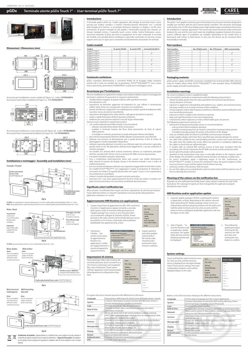
尺寸 / Dimensions (mm)
183
200
231.7
10.8 42.5 230
212.5
200
2
97
230
28200
225.7
200
127.8
56 221.7
123.4
100
100
60
60 176
83.5
83.5
132
13010071
114.7
44.7
12.4100
124.6133.9
Introduction
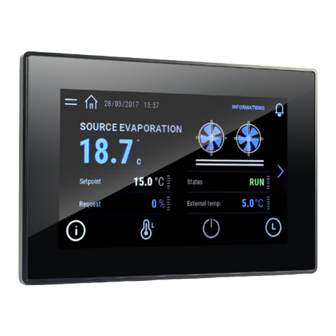
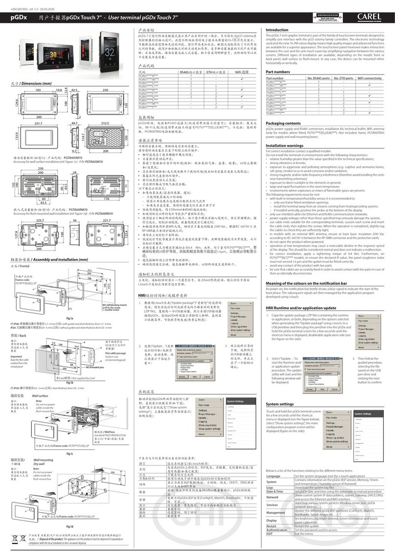
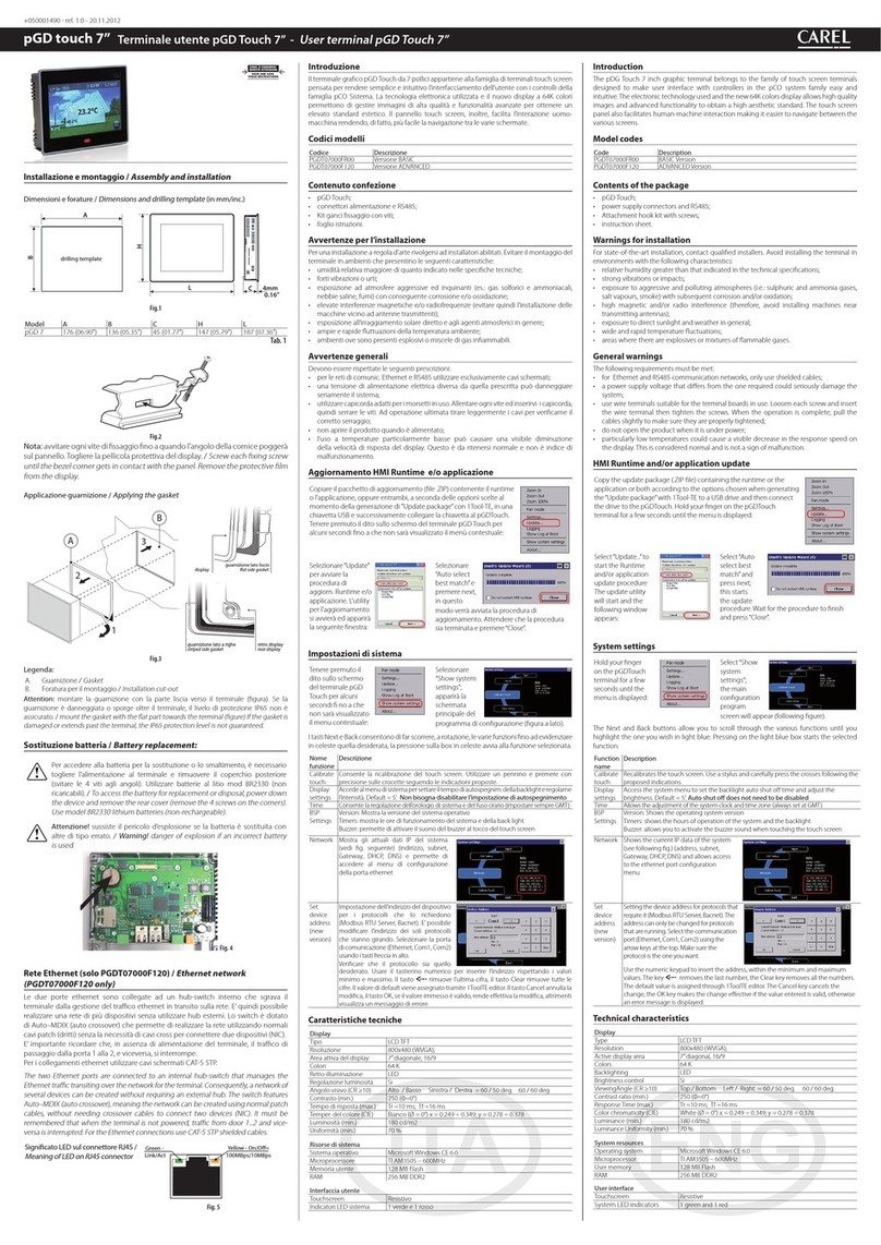
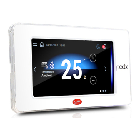
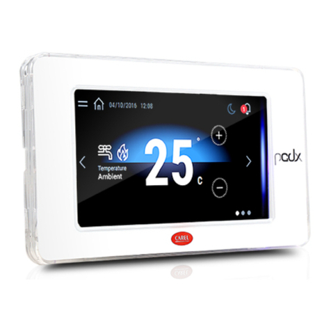
The pGDx 7 inch graphic terminal is part of the family of touchscreen terminals designed to
simplify user interface with the pCO sistema family controllers. The electronic technology
used and the new 16.7M colour display means high quality images and advanced functions
are available for a superior appearance. The touchscreen panel moreover makes interaction
between the user and the unit much easier by simplifying navigation between the various
screens. Dierent types of installation are available, depending on the model: front or
back panel, wall surface or ush-mount. In any case, the device can be mounted either
horizontally or vertically.
Part numbers
Part number No. RS485 ports No. ETH ports WiFi connectivity
PGR07****B*** 1 - -
PGR07****W*** 1 - ü
PGR07****D*** 2 - -
PGR07****C*** 1 1 -
PGR07****R*** 1 1 ü
PGR07****F*** 2 2 -
PGR07****G*** 2 2 ü
PGB07****E*** - 1 -
PGB07****M*** - 2 -
PGB07****I*** - 2 ü
Packaging contents
pGDx; power supply and RS485 connectors; installation kit; technical leaet, WiFi antenna
(only for models where tted, PG*07***D[G,I,R,W]***). Not included: frame, PGTA00TRX0
power supply and wall mounting boxes.
Installation warnings
For correct installation contact a qualied installer.
Do not install the terminals in environments with the following characteristics:
• relative humidity greater than the value specied in the technical specications;
• strong vibrations or knocks;
• exposure to aggressive and polluting atmospheres (e.g.: sulphur and ammonia fumes,
salt spray, smoke) so as to avoid corrosion and/or oxidation;
• strong magnetic and/or radio frequency interference (therefore avoid installing the units
near transmitting antennae);
• exposure to direct sunlight or the elements in general;
• large and rapid uctuations in the room temperature;
• environments where explosives or mixes of ammable gases are present.
The following requirements must be met
• with built-in temperature/humidity sensor, it is recommended to:
– only use frame tted ventilation openings
– install the terminal away from air streams coming from heating/cooling systems
– if installed vertically, position the probe at the bottom of the display
• only use shielded cables for Ethernet and RS485 communication networks;
• power supply voltages other than those specied may seriously damage the system;
• use cable ends suitable for the corresponding terminals. Loosen each screw and insert
the cable ends, then tighten the screws. When the operation is completed, slightly tug
the cables to check they are suciently tight;
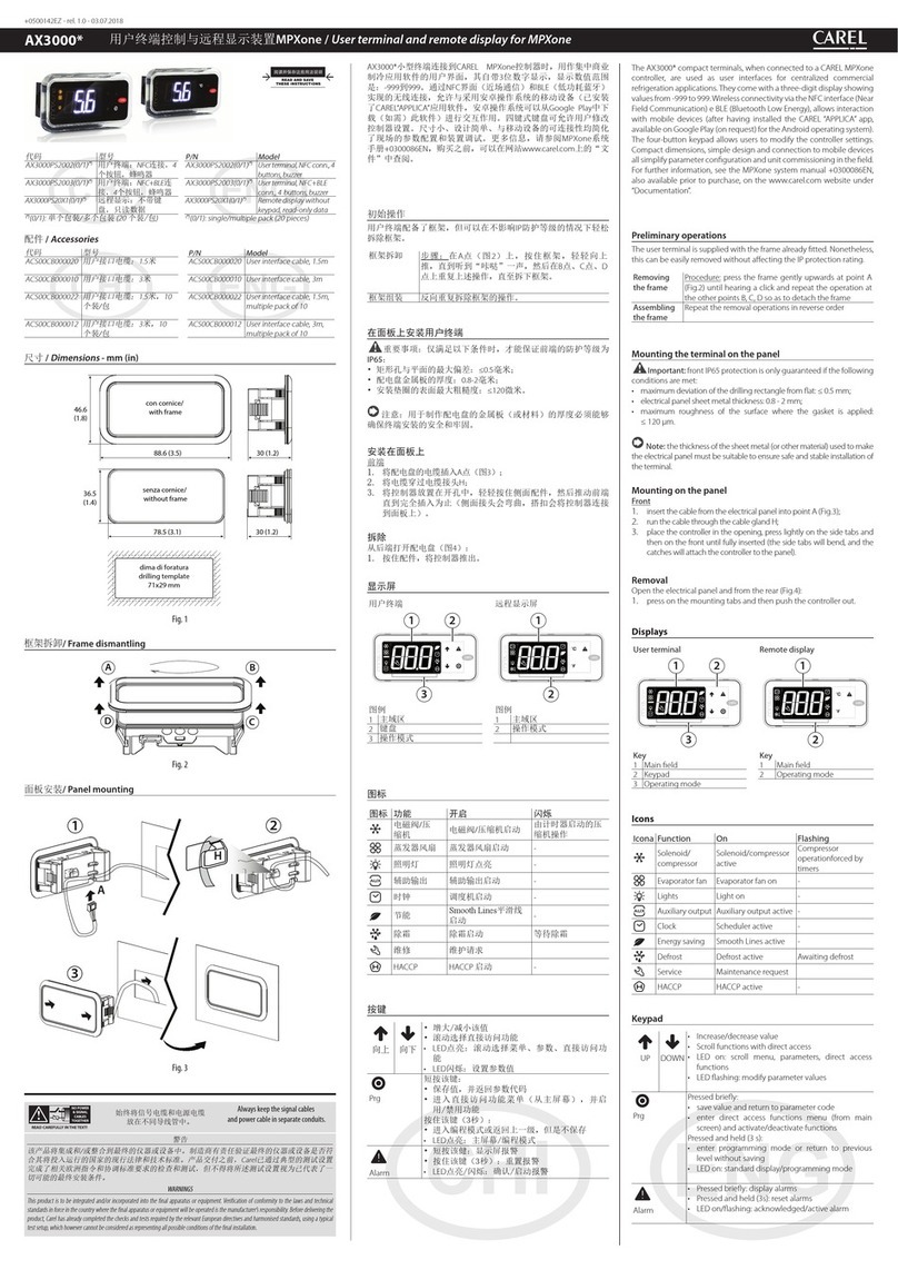
• in models with an external WiFi antenna, ensure at least basic insulation (500 Vac
according to IEC 60730-1) between the RP-SMA connector and the protective earth;
• do not open the product when powered;
• operation at low temperatures may cause a noticeable decline in the response speed
of the display. This should be considered normal and does not indicate a malfunction.
• for correct installation, apply a tightening torque of 0.4 Nm. Furthermore, on
PG*07***[N,T]**** models, to ensure the declared IP value, the panel roughness index
must not exceed 1.6 µm and the gasket must be tted correctly;
• avoid any contact of the product with live parts.
• be sure that cables are accurately xed in order to avoid contact with live parts in case of
their accidentally disconnection.
Meaning of the colours on the notification bar
At power-on, the notication bar briey shows a blue signal to indicate the start of the
boot phase. The subsequent signals are then managed by the application program
developed using c.touch.
HMI Runtime and/or application update
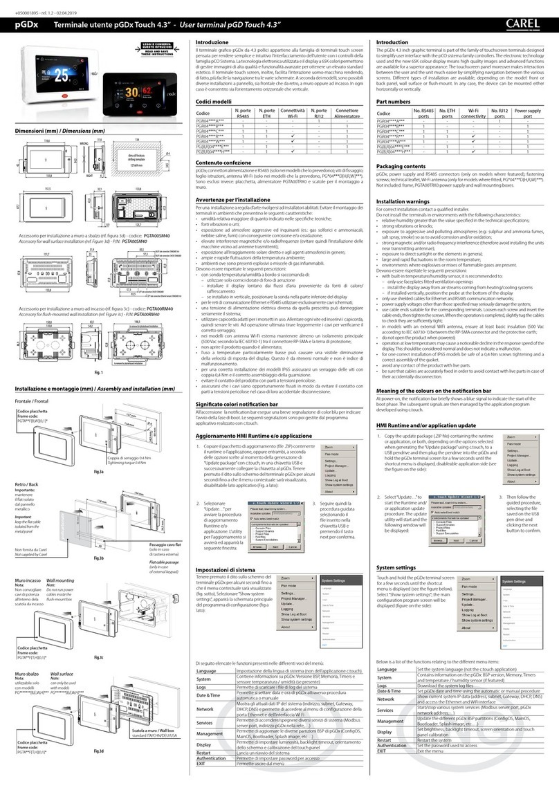
1. Copy the update package (.ZIP le) containing the runtime
or application, or both, depending on the options selected
when generating the “Update package”using c.touch, to a
USB pendrive and then plug the pendrive into the pGDx and
hold the pGDx terminal screen for a few seconds until the
shortcut menu is displayed, disableable application side (see
the gure on the side):
2. Select “Update…” to
start the Runtime and/
or application update
procedure. The update
utility will start and the
following window will
be displayed:
3. Then follow the
guided procedure,
selecting the le
saved on the USB
pen drive and
clicking the next
button to conrm.
System settings
Touch and hold the pGDx terminal screen
for a few seconds until the shortcut
menu is displayed (see the gure below).
Select “Show system settings”; the main
conguration program screen will be
displayed (gure on the side):
Below is a list of the functions relating to the dierent menu items:
Language Set the system language (not the c.touch application)
System Contains information on the pGDx: BSP version, Memory, Timers
and temperature / humidity sensor (if featured)
Logs Download the system log les
Date & Time Set pGDx date and time using the automatic or manual procedure
Network Show current system IP data (address, subnet, Gateway, DHCP, DNS)
and access the Ethernet and WiFi interface
Services Start/stop various system services (Modbus server port, pGDx
network address,…)
Management Update the dierent pGDx BSP partitions (CongOS, MainOS,
Bootloader, Splash image, etc.…)
Display Set brightness, backlight timeout, screen orientation and touch
panel calibration
Restart Restart the system
Authentication Set the password used to access
EXIT Exit the menu
墙面安装配件 (如图1c) - 产品代码:PGTA00SM70
Accessory for wall surface installation (ref. Figure 1c) - P/N: PGTA00SM70
嵌入式安装配件 (如图1d) - 产品代码: PGTA00RM70
Accessory for ush-mounted wall installation (ref. Figure 1d) - P/N: PGTA00RM70
正面 / Frontal
200
188
213
115.5
100
88
M3 self-blocking inserts
or Ø 4.2 for screw
+ counter-screw
Fig.1a
(*) IP66: 带垫圈且薄片厚度在1.2 - 6 mm之间 / with gasket and sheet thickness from 1.2 - 6 mm
IP20: 无垫圈且薄片厚度在0.8 - 6 mm之间 / without gasket and sheet thickness from 0.8 - 6 mm
背面 / Back
M3 threaded pins
184
200
10.4
5.4
125.6
100
R4
policarbonate
Fig.1b
(*) IP20: 薄片厚度在0.8 - 2 mm之间 / sheet thickness from 0.8 - 2 mm
墙面安装 Wall surface
Fig.1c
墙面安装/ Wall mounting
干砌墙 Dry wall
220
122
Fig.1d
扁平线缆穿过
(仅适用于采用外
置键盘)
Flat cable passage
(only in case
of external keypad)
外框产品代码/Frame code: PGTA**F[T,H][2,3]*
非Carel供货 / Not supplied by Carel
备注:
请勿将电源线
穿过嵌入式 安
装盒
Note:
Do not run power
cables inside the
ush-mount box
备注:
请勿将电源线
穿过嵌入式 安
装盒
Important:
keep the at cable
isolated from the
metal panel
暗线箱 / Wall box
standard ITA/CHN/DEU/USA
意大利/中国/德国/美国
标准
外框产品代码
Frame code:
PGTA**F[B,W][2,3]*
(*)
组装和安装 /
Assembly and installation (mm)
外框产品代码/Frame code: PGTA**F[T,H][2,3]*
备注:
请勿将电源线
穿过嵌入式 安
装盒
Note:
Do not run power
cables inside the
ush-mount box
产品介绍
pGDx 7寸图形终端是触摸式显示屏产品系列中的一部分,专为简化与pCO sistema系
列控制器的对接而设计。此图形终端采用的电子技术及新型的16.7百万色彩显示,
可提供高品质图像和先进的功能,图形界面更加出众。触摸式面板简化了不同界面
之间的导航,使用户和机组之间的互动更加简单。有多种安装类型的不同产品可提
供:正面或背板、墙面安装或嵌入式安装。但不管采用哪种型号,此终端均可以水
平安装或垂直安装。
产品代码
代码 RS485端口数量 ETH端口数量 WiFi 连接
PGR07****B*** 1 - -
PGR07****W*** 1 - ü
PGR07****D*** 2 - -
PGR07****C*** 1 1 -
PGR07****R*** 1 1 ü
PGR07****F*** 2 2 -
PGR07****G*** 2 2 ü
PGB07****E*** - 1 -
PGB07****M*** - 2 -
PGB07****I*** - 2 ü
包装明细
pGDx终端,电源和RS485连接头(仅适用带此接头的型号);安装组件;技术文
档,Wi-Fi天线(仅适用带此接头的型号PG*07***D[G,I,R,W]***)。不包括:塑料外
框,PGTA00TRX0电源和暗线盒。
安装注意事项
为确保安装正确,请联络有资质的安装工。
请勿将终端安装在具有下列特点的环境中:
• 相对湿度高于技术规格中规定的值;
• 具有强烈震动或冲击;
• 暴露于侵蚀和污染中的环境(例如:硫和氨的气体、盐雾、烟雾),以防止腐蚀
和/或氧化;
• 存在强烈磁性和/或无线电频率干扰的环境(因此切勿安装在发射天线附近);
• 暴露在阳光直射的环境中。
• 房间温度波动大且急速;
• 存在爆炸物或可燃气体混合物。
以下要求必须满足:
• 如果内置温度/湿度传感器,建议:
–只使用配置通风口的面板
–将显示屏安装在远离制冷制热系统气流外
–如果是垂直安装,请将传感器定位在显示屏下方
• 仅使用屏蔽线,用于Ethernet和RS485通讯网络;
• 如使用标定以外的电压可能会严重损坏系统;
• 使用适合于相应终端的线缆头。松开每个螺丝并插入线缆头,然后紧固螺丝。操
作完成后,轻轻拉动线缆,检查线缆是否已固定好;
• 如触摸屏使用外置WiFi天线,确保至少基本的隔离 (500 Vac,根据IEC 60730-1) 在
RP-SMA接头和保护接地之间;
• 请勿在上电时打开本终端;
• 低温运行可能导致显示屏反应速度的显著下降。此种现象被视为正常现象,而不
会标识为故障;
• 正确安装方式为螺丝紧固扭力为0.4 Nm;此外,对于型号PG*07***[N,T]****,要
确保标称的IP防护等级,面板粗糙度指数不能超过1.6µm,且垫圈必须配置合
适;
• 避免接触终端上任何带电的部件;
• 确保线缆固定准确,避免接触带电部件,以防终端发生意外断开。
通知栏上的颜色含义
上电时,通知栏短时显示一个蓝色信号,表示boot阶段启动。随后的信号将由
c.touch开发的应用程序进行管理。
HMI运行时间和/或程序更新
1. 根据用c.touch生成(“Update package” )"更新包"时选择的
选项,将包含运行时间或程序或两个都有的的更新包
(.ZIP le),复制到一个USB驱动器,然后再将USB驱动器
插到pGDx,按住pGDx终端显示屏持续几秒钟,直到显
示快捷菜单,可使程序侧失效(参考右侧图):
2. 选择(“Update…”)更新
运行时间和/或程序
更新。启动更新,然
后将显示下面这个
窗口:
3. 然后按照引导的
步骤,选择保存
在USB驱动器上
的文件,并且点
击下一个按钮以
确认。
系统设定
触动并按住pGDx终端界面持续几秒
钟,直到显示快捷菜单(如下图),
选择"显示系统设定"(“Show system
settings”);主要配置程序界面将显示(
如侧面图):
下表为与不同菜单项目有关的功能清单:
语言 设定系统语言(非c.touch程序)
系统 包含在pGDx上的信息:BSP版本,存储器,定时器和温度/湿
度传感器(如果已配置)
日志 下载系统日志文件
日期&时间 使用自动或手动步骤设定pGDx的日期和时间
网络 显示当前系统IP数据(地址、子网络、网关、DHCP、DNS)并访
问以太网和WiFi界面
服务 启动/停止不同系统设备(Modbus服务器端口,pGDx网络地
址…)
管理 更新不同pGDx BSP分区(CongOS, MainOS, Bootloader,开机图
像,等等…)
显示 设定亮度,背光超时,界面方向和触控面板校准
重启 重启系统
授权 设定密码,用于访问
退出 退出菜单
CAREL Industries HQs
Via dell’Industria, 11 - 35020 Brugine - Padova (Italy)
Tel. (+39) 0499716611 – Fax (+39) 0499716600 – www.carel.com – e-mail: carel@carel.com +05C001950 - rel. 1.2 - 19.09.2019
CAREL保留不预先告知而修改产品的权力。
CAREL INDUSTRIES reserves the right to modify the features of its products without prior notice.
Technical specifications
Display
Type LCD TFT
Resolution 800x480 Wide
Active display area 7” diagonal
Colours 16,7M
Backlighting LED - Lifetime 20 khrs @ 25 °C
Brightness control Yes - auto-o by default after 15 min
Visual angle (CR ≥10) Up/Down (50/70 deg.) - Left/Right (70/70 deg.)
Contrast (typical) 400 (Φ=0°)
Brightness (typical) 500 cd/m2
User interface
Touchscreen Resistive
System signal LEDs 8-colour notication bar
Interfaces
ETH0, ETH1 Ethernet ports Auto-MDIX 10/100 Mbit - RJ45 female
STP CAT 5 cable Lmax = 100 m
Wi-Fi IEEE 802.11 b/g/n - STATION/ACCESS POINT mode
Built-in/external antenna based on model
Max Transmit Power = 17dBm
External antenna remote mounting Lmax = 2 m
External antenna connector RP-SMA female
(for models PG*07***D[G,I,R,W]***)
USB port () Host interface 2.0 - micro USB -B - 150 mA max
(do not use to charge devices) - Lmax = 1m
COM1 (), COM2 Serial ports RS485 max 115,2 Kb/s
Removable screw connector 3,81mm pitch
Shielded twisted pair cable AWG 20-22 for ±
Lmax = 500m - tightening torque 0.25Nm (2.2lbf x in)
Master/Slave set via dipswitch (Fig.3)
Temperature / humidity probe 0 to 50 °C / 20 to 80% rH
0 to 50 °C ±1 °C (static air)
20 to 80% ±5% (static air)
() only for service. The USB port can be damaged by ESD (Electro-Static Discharges).
It’s recommended to adopt appropriate precautions in order to avoid failures.
() opto-isolated for model PGR07****[C,D,F,G,R]***
Functions
Vector graphics Yes, includes SVG 1.0 support
Dynamic objects Yes Visibility, position, rotation
TrueType fonts Yes
Multi-protocol Yes
Logs and trends Yes. Limited to Flash memory capacity
Multilanguage Yes, run-time language setting and limited only by
available memory
Recipes Yes. Limited to Flash memory capacity
Alarms Yes
Event list Yes
Passwords Yes
Real Time Clock () Yes, with backup battery
Screen saver Yes
Buzzer () “Beep”when pressing the touchscreen (settable)
() only on models where featured
Electrical
Power supply 24Vdc Class 2/SELV supplied by PGTA00TRX0 accessory
Lmax = 50 m (-)- cable cross section AWG 12-20
tightening torque 0.8 Nm (7 lbf x in)
Max Power Absorption 9 W
Fuse Automatic
Weight Approx. 600 g
Battery Non-rechargeable lithium model BR1225
Software class and structure A
Purpose of control operation control
Controller construction incorporated control (PG*07***[D,F,N,T,W]****)
Type of automatic action type 1 action
Heat and re resistance Cat. D
Overvoltage category Cat. III
Insulation class Class III
() For PG*07***W**** models with ush mounting, accessory PGTA00TRX0 must be
installed in a dedicated box - () Power supply range: 24 Vdc ± 10%
Environmental conditions
Operating temperature PG*07***[D,N,T]****: -20 to 60 °C
PG*07***[F,W]****: 0 to 50 °C
Storage temperature PG*07********: -30 to 70 °C
Maximum operating and
storage relative humidity
85% @ 40 °C non-condensing
Ingress protection PG*07***T****: IP66, NEMA Type 1 (front)
PG*07***N****: IP66, NEMA Type 4X indoor (front)
if coupled with PGTA**F [B,W][2,3]* (frame)
PG*07***[D,F,W]****: IP20, NEMA Type 1 (front)
Pollution degree 3
废弃物处置规定 / Disposal regulations
•
请勿将此设备作为城市固废处理;请将其送至正确的处理中心。
•
此装置中含有电池,在进行处置前,请先断开电源,再将后盖拆下。
•
使用或处置不当可能对人体健康和环境都有不良影响。
•
必须按照当地法规规定的公共或个人废弃物回收系统对此装置废弃物进行处
置。
•
如果出现电子和电气废弃物违法处置,则将依据当地现行法律对废弃物处置的
规定进行处罚。
•
Do not dispose of the product as solid municipal waste; take it to the proper collection
centres.
•
The product contains a battery, power down the device, remove the rear cover and
must be removed, before proceeding with disposal.
•
Improper use or disposal could have a negative eect on human health and the
environment.
•
Public or private waste collection systems dened by local legislation must be used for
its disposal.
•
in the event of illegal disposal of waste electrical and electronic equipment, penalties
have been established by the current local laws regarding disposal.
J1 J2 J3 J4 J5
J14
J10
J13
J12 J15
dracSMBdracsuBdleiF
4 3 2 1
J11 pLAN
Tx/Rx
GND
J26 FBus2
J24
+
XXXXXXXXXXXX
ETH0 ETH0
c.pCO/pCO
Access-Point/Station
J1 J2 J3 J4 J5
J14
J10
J13
J12 J15
dracSMBdracsuBdleiF
4 3 2 1
J11 pLAN
J25 BMS2 J26 FBus2
J24
+
XXXXXXXXXXXX
c.pCO
J1 J2 J3 J4 J5
J14
J10
J13
J12 J15
dracSMBdracsuBdleiF
4 3 2 1
Tx/RxGND
J25 BMS2 J26 FBus2
J24
+
XXXXXXXXXXXX
c.pCO/pCO
GND
–
+
L N
+ –
PGTA00TRX0
230 Vac
24 Vdc
+
–
GND
–
+
J25 BMS2
J11 pLAN
COM1
COM2
J1 J2 J3 J4 J5
J14
J10
J13
J12 J15
dracSMBdracsuBdleiF
4 3 2 1
J11 pLAN
Tx/Rx
GND
J26 FBus2
J24
+
XXXXXXXXXXXX
c.pCO/pCO
Access-Point/Station
c.pCO mini
J1 J2 J3 J4 J5
J14
J10
J13
J12 J15
dracSMBdracsuBdleiF
4 3 2 1
Tx/RxGND
J25 BMS2
Tx/Rx
GND Tx/Rx
GND
J26 FBus2
J24
+
XXXXXXXXXXXX
c.pCO/pCO
GND
–
+
L N
+ –
PGTA00TRX0
230 Vac
24 Vdc
+
–
GND
–
+
ETH1 ETH0
J25 BMS2
J11 pLAN
COM1
COM2
以太网开关配置 / Ethernet switch configuration 双MAC以太网配置 / Dual MAC Ethernet configuration
Fig. 4a Fig. 4b
网络连接 /
Network connection:
1 3 5
710 9 8 114 2
6
SW2
SW1
Fig.2
Mounting/安装 Connectivity/通讯
Description/描述
PG*07***[F,T]****
Front Panel/前面板
PG*07***N****
Front Panell /
前面板
PG*07***D****
Rear Panel /背板
PG*07***W****
Wall Mounting
墙面安装
PGR07****[B/W]***
PGR07****D***
PGR07****[C/R]***
PGR07****[F/G]***
PG*07****E***
PG*07****[I/M]***
1MicroUSB rear/背面   
2MicroUSB front/正面  
3external keypad connector/
外置小键盘连接头 
4temperature and humidity probe ()/温
度和湿度传感器()

(option)
5Wi-Fi antenna SMA connector (RP-SMA)
Wi-Fi 天线SMA连接头(RP-SMA) 
6RS485 port COM1/RS485端口COM1    
7RS485 port COM2/RS485端口COM2  
8Ethernet port ETH0/以太网口ETH0    
9Ethernet port ETH1/以太网口ETH1  
10 notication bar/通知栏      
11 power supply/电源          
Tab. 2
如果
COM1
端口用作
pLAN(Modbus通过pLAN协议)或显示端口:请勿在网络中的第一
个和最后一个设备上连接120欧姆电阻。可连接到网络中的最大设备数量为32个,
最长距离为500m。
注意:仅
COM1
端口可用作
pLAN(Modbus通过pLAN协议)。
()定期检查传感器通风孔是清洁的。
If COM1 port is used as pLAN (Modbus over pLAN) or display port: DO NOT connect the
resistors 120 ohm termination on the rst and last device in the network. The maximum
number of devices that can be connected in the network is 32 and the maximum length
of the network is 500m.
Attention: only COM1 port can be used as a pLAN (Modbus over pLAN protocol).
() Periodically check that the probe ventilation holes are clean.
串行DIP开关配置 / Serial
Dipswitch Conguration
SLAVE/从控 MASTER/主控
Fig.3
端口电阻
terminator resistor
120 ohm - OFF 1 2 3
ON
1 2 3
ON
1 2 3
ON
1 2 3
ON
Pull-Up
Pull-Down - OFF
Pull-Up
Pull-Down - ON
(pLAN)
端口电阻
terminator resistor
120 ohm - ON
连接到pCO/c.pCO控制器 /
Connection to
pCO/c.pCO
NEMA 4X前面板 / NEMA 4X Frontal
214
R2
116
Fig.1e
外框产品代码
PGTA**F[B,W][2,3]*
薄板厚度在 1.2~6 mm之间
Sheet thickness from 1.2 - 6 mm
技术规格
显示屏
类型 LCD TFT
分辨率 800x480
有效显示区域 7”
色彩 16,7M
背光 LED - 使用寿命 20 khrs @ 25 °C
亮度控制 是 - 自动关闭,默认为15分钟后
视角 (CR ≥10) 上/下 (50/70度) - 左/右(70/70度)
对比(典型) 400 (Φ=0°)
亮度(典型) 500 cd/m2
用户界面
触摸屏 阻性
系统信号LED灯8色通知栏
接口
ETH0, ETH1以太网口 自动极性识别10/100 Mbit - RJ45内插口
STP CAT 5 线缆最长 = 100 m
Wi-Fi IEEE 802.11 b/g/n - 站/接入点模式
根据型号可分为内置/外置天线
最大传输功率 = 17dBm
外置天线远程安装最长距离 = 2 m
外置天线连接头RP-SMA内插口
(适用于型号PG*07***D[G,I,R,W]***)
USB端口() 主机接口2.0 - 微型USB -B - 150 mA最大
(请勿使用充电设备) - 最长距离= 1m
COM1 (), COM2串行端口 RS485 最大115.2 Kb/s
可拆卸螺接头3.81mm 插脚
屏蔽双绞线AWG 20-22 ±
最长= 500m - 紧固扭力0.25Nm (2.2lbf x)
通过DIP开关设定主/从 (Fig.3)
温度/湿度传感器 0 ~ 50 °C / 20 ~ 80% rH
0 ~ 50 °C ±1 °C (静态空气)
20 ~ 80% ±5% (静态空气)
() 仅用于服务操作。USB端口可能会被ESD(静电释放)。建议采用恰当的预防
措施,以防止故障。
()光电隔离,适用于PGR07****[C,D,F,G,R]***
功能
向量图 是,包括支持SVG 1.0
动态对象 是,清晰度,位置,轮值
TrueType字体 是
多协议 是
日志和趋势 是,受限于闪存容量
多语言 是,运行时间语言设定,并且仅受限于可用的存
储器
配方 是,受限于闪存容量
报警 是
事件清单 是
密码 是
实时钟() 是,带备用电池
屏保 是
蜂鸣器 () “Beep” ,当按压触摸屏时(可设定)
() 仅适用于有此配置的型号
电气规格
电源 24Vdc 2类/SELV,通过PGTA00TRX0供电
电源线缆最长 = 50 m (-)- 线缆截面 AWG 12-20
紧固扭力0.8 Nm (7 lbf x in)
最大功耗 9 W
熔丝 自动的
重量 大约600 g
电池 非充电锂电池,型号BR1225
软件等级和结构 A
控制方式 运行控制
控制器结构 集成控制(PG*07***[D,F,N,T,W]****)
自动动作类型 类型1动作
耐热和防火类别 D类
过压类别 III类
绝缘类别 III类
() 对于嵌入式安装的型号,PG*07***W**** PGTA00TRX0必须安装到专用的接线盒 -
() 电源范围:24 Vdc ± 10%
环境条件
运行温度 PG*07***[D,N,T]****: -20 ~ 60 °C
PG*07***[F,W]****: 0 ~ 50 °C
储存温度 PG*07********: -30 ~ 70 °C
最大运行和储存相对湿度 85% @ 40 °C 无凝露
防护等级 PG*07***T****: IP66, NEMA 类型1 (前面)
PG*07***N****: IP66, NEMA 类型4X室内(前面)
如果与PGTA**F [B,W][2,3]*结合 (外框)
PG*07***[D,F,W]****: IP20, NEMA类型1 (前面)
污染等级 3
IMPORTANT WARNINGS: The CAREL product is a state-of-the-art product, whose operation is specied in the technical
documentation supplied with the product or can be downloaded, even prior to purchase, from the website www.carel.com.
- The client (builder, developer or installer of the nal equipment) assumes every responsibility and risk relating to the phase of
conguration the product in order to reach the expected results in relation to the specic nal installation and/or equipment.The
lack of such phase of study, which is requested/indicated in the user manual, can cause the nal product to malfunction of which
CAREL can not be held responsible. The nal client must use the product only in the manner described in the documentation
related to the product itself. The liability of CAREL in relation to its own product is regulated by CAREL’s general contract
conditions edited on the website www.carel.com and/or by specic agreements with clients.
Disposal of the product: The appliance (or the product) must be disposed of separately in compliance with the
local standards in force on waste disposal.
Standards
Safety UL UL60730-1
sch. CB IEC60730-1
EMC CE EN61000-6-1 / EN61000-6-2
EN61000-6-3 / EN61000-6-4
EN55014-1 / EN55014-2
Radio Red EN301489-1/EN301489-17
EN300328
FCC Part.15 Subpart.B
Other certication under approvals, please contact Carel
Representatives for other details
NO POWER
& SIGNAL
CABLES
TOGETHER
READ CAREFULLY IN THE TEXT!
Always keep the
signal cables and
power cable in
separate conduits.
重要说明
CAREL产品是一种先进的装置,其操作在产品随附的技术文件中有详细说明,也可在购买之
前从www.carel.com网站下载。对于为达到与最终安装和/或设备相关的特定预期结果相关的产
品配置上的一切责任和风险,均由客户(最终设备的制造商、开发商或安装供应商)承担。
如果在所述阶段未完成用户手册中要求/指示的内容,就可能导致最终产品故障;在这种情况
下,CAREL不承担任何责任。客户必须通过与产品相关的文档所描述的方式使用产品。在CAREL
一般合约条件中,对CAREL在产品方面的责任进行了规定,详情可从www.carel.com网站和/或与
客户签订的特定协议进行了解。
产品处置
本装置(或产品)必须依照当地关于废弃物处理的有效法规单独进行处理。
合规性
安全 UL UL60730-1
sch. CB IEC60730-1
EMC CE EN61000-6-1 / EN61000-6-2
EN61000-6-3 / EN61000-6-4
EN55014-1 / EN55014-2
Radio Red EN301489-1/EN301489-17
EN300328
FCC Part.15 Subpart.B
其他获得批准的认证,请联系Carel代表以获取其他详细信息
NO POWER
& SIGNAL
CABLES
TOGETHER
READ CAREFULLY IN THE TEXT!
请将电源线和信
号线
放在不同导线管
内。
This manual suits for next models

10

Other Carel Touch Terminal manuals

Carel pGDx Touch 4.3 User manual

Carel

Carel pGDx Touch 4.3 User manual

Carel pGDx User manual

Carel

Carel pGDx User manual

Carel pGD touch 7 User manual

Carel

Carel pGD touch 7 User manual

Carel pGDx User manual

Carel

Carel pGDx User manual

Carel AX5000 User manual

Carel

Carel AX5000 User manual

Carel pGDx Series Instruction Manual

Carel

Carel pGDx Series Instruction Manual

Carel pGD Series User manual

Carel

Carel pGD Series User manual

Carel pGD touch PGDT04000FS00 Instruction Manual

Carel

Carel pGD touch PGDT04000FS00 Instruction Manual

Carel AX3000 Series User manual

Carel

Carel AX3000 Series User manual

Carel pGD Series User manual

Carel

Carel pGD Series User manual

Carel PLD Series User manual

Carel

Carel PLD Series User manual

Carel TH Tune User manual

Carel

Carel TH Tune User manual

Carel pGD Series User manual

Carel

Carel pGD Series User manual

Carel pGDx Touch 4.3” User manual

Carel

Carel pGDx Touch 4.3” User manual

Carel pGD touch Instruction Manual

Carel

Carel pGD touch Instruction Manual

Carel pGD Touch Instruction Manual

Carel

Carel pGD Touch Instruction Manual

Carel PAD User manual

Carel

Carel PAD User manual

Carel IR U Series User manual

Carel

Carel IR U Series User manual

Carel MTST User manual

Carel

Carel MTST User manual

Carel pGDx User manual

Carel

Carel pGDx User manual

Carel pGD Touch User manual

Carel

Carel pGD Touch User manual

Carel EasySet HYPW User manual

Carel

Carel EasySet HYPW User manual

Carel PAD User manual

Carel

Carel PAD User manual

Carel pGD Series User manual

Carel

Carel pGD Series User manual

Popular Touch Terminal manuals by other brands

Teltonika FMM125 Quick manual

Teltonika

Teltonika FMM125 Quick manual

FEC ST-1120W user manual

FEC

FEC ST-1120W user manual

VisionTek GL-14 POS user manual

VisionTek

VisionTek GL-14 POS user manual

Knick VariTrans P 27000-S008 instructions

Knick

Knick VariTrans P 27000-S008 instructions

CipherLab 8500 Series Operator's reference guide

CipherLab

CipherLab 8500 Series Operator's reference guide

Varec Data Entry Terminal 8620 Installation and... Installation and operation manual

Varec

Varec Data Entry Terminal 8620 Installation and... Installation and operation manual

Hughes DiRECWAY DW7700 Supplemental user guide

Hughes

Hughes DiRECWAY DW7700 Supplemental user guide

Nokia 7368 ISAM ONT G-240W-C Product guide

Nokia

Nokia 7368 ISAM ONT G-240W-C Product guide

Wyse WY-60 user guide

Wyse

Wyse WY-60 user guide

Beckhoff EL9930 Operation manual

Beckhoff

Beckhoff EL9930 Operation manual

AMP 8200 Quick reference instructions

AMP

AMP 8200 Quick reference instructions

Mitsubishi Electric GOT 1000 Series Connection manual

Mitsubishi Electric

Mitsubishi Electric GOT 1000 Series Connection manual

IEE PDK-UP05 Series reference guide

IEE

IEE PDK-UP05 Series reference guide

AT&T Definity 7406 Plus user guide

AT&T

AT&T Definity 7406 Plus user guide

Mitsubishi Electric GOT 1000 Series manual

Mitsubishi Electric

Mitsubishi Electric GOT 1000 Series manual

POSIFLEX XT-3015 user manual

POSIFLEX

POSIFLEX XT-3015 user manual

Castles Technology VEGA3000 user manual

Castles Technology

Castles Technology VEGA3000 user manual

ZKTeco iFace Series installation guide

ZKTeco

ZKTeco iFace Series installation guide

manuals.online logo
manuals.online logoBrands
  • About & Mission
  • Contact us
  • Privacy Policy
  • Terms and Conditions

Copyright 2025 Manuals.Online. All Rights Reserved.