ISIC DuraPANEL 10.6 User manual

User Reference Manual –DuraPANEL 10.6”
PN: 08140-000 Rev A Page 1
User Manual
DuraPANEL 10.6”

User Reference Manual –DuraPANEL 10.6”
PN: 08140-000 Rev A Page 2
Disclaimer
ISIC A/S makes no representation or warranties with respect to the contents or use of this
manual, and specifically disclaims any express or implied warranties of merchantability or
fitness for any particular purpose. Further, ISIC A/S reserves the right to revise this
publication and to make changes to its content at any time, without obligation to notify any
person or entity of such revisions or changes.
Image sticking: If the monitor is operated with static images (logo’s etc) it will inevitably
lead to images sticking on the display (like on old CRT’s).
FCC Warning
Computing devices and peripherals generate and radiate radio frequency energy, and if not
installed and used in accordance with the instructions advised by ISIC A/S, it may cause
interference to radio communication.
The DuraPANEL 10.6”manufactured by ISIC A/S, is designed to comply with the emerging
generic EEC standards, that cover applications in maritime environment.
ISIC A/S is complying with the WEEE directive within the European Union, stating that
electronic and electric products must be collected separately.
Products are marked according to the directive.
Copyright 2017 ISIC A/S
ISIC A/S
Edwin Rahrsvej 54
DK-8220 Brabrand
Denmark
Phone: +45 70 20 70 77
Fax: +45 70 20 79 76
Web: http://www.isic-systems.com

User Reference Manual –DuraPANEL 10.6”
PN: 08140-000 Rev A Page 3
Table of Contents
1FEATURES ............................................................................................................. 4
2GENERAL CONSIDERATIONS ON INSTALLATION AND OPERATION ....................... 5
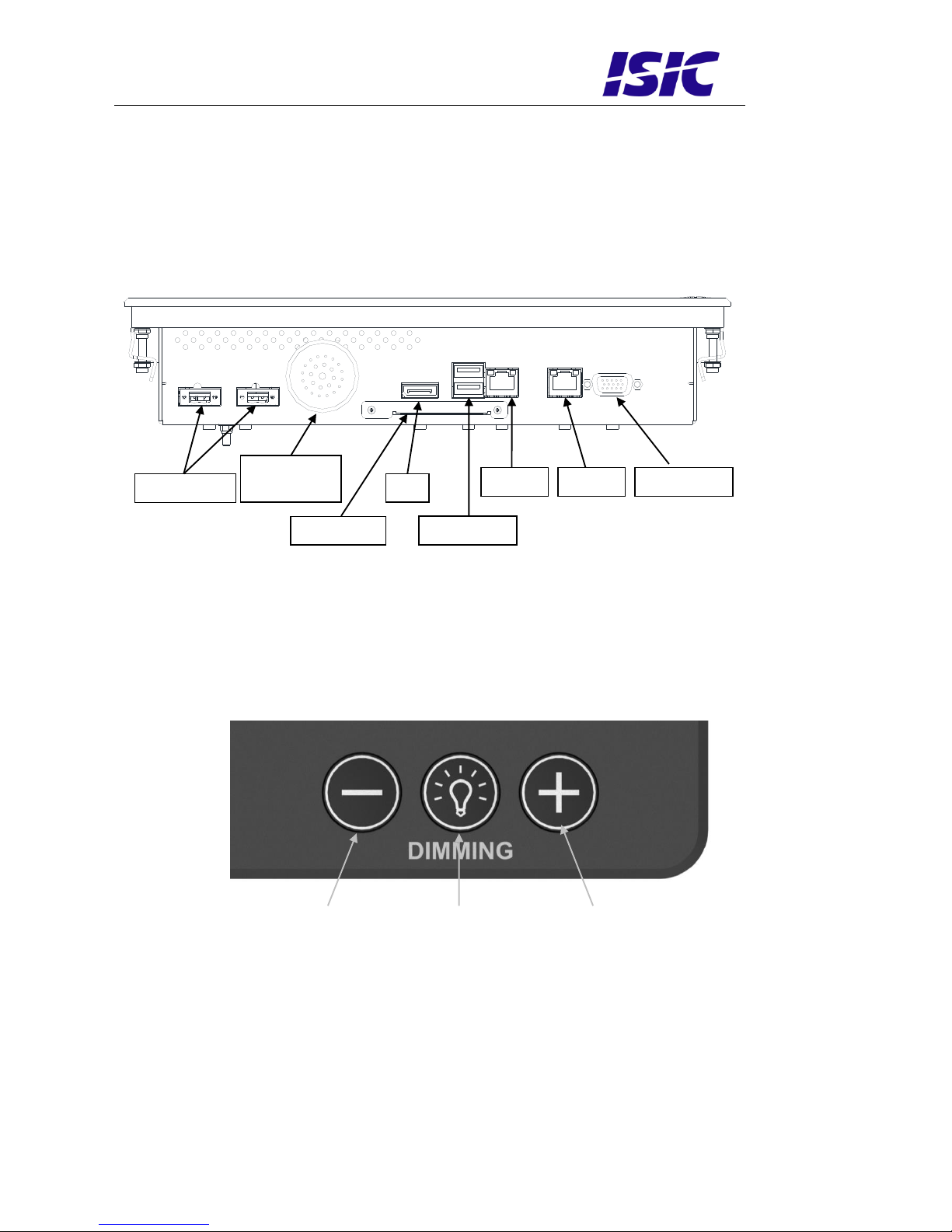
3DURAPANEL CONNECTIONS .................................................................................. 6
4DURAPANEL FRONT PANEL CONTROLS.................................................................. 6
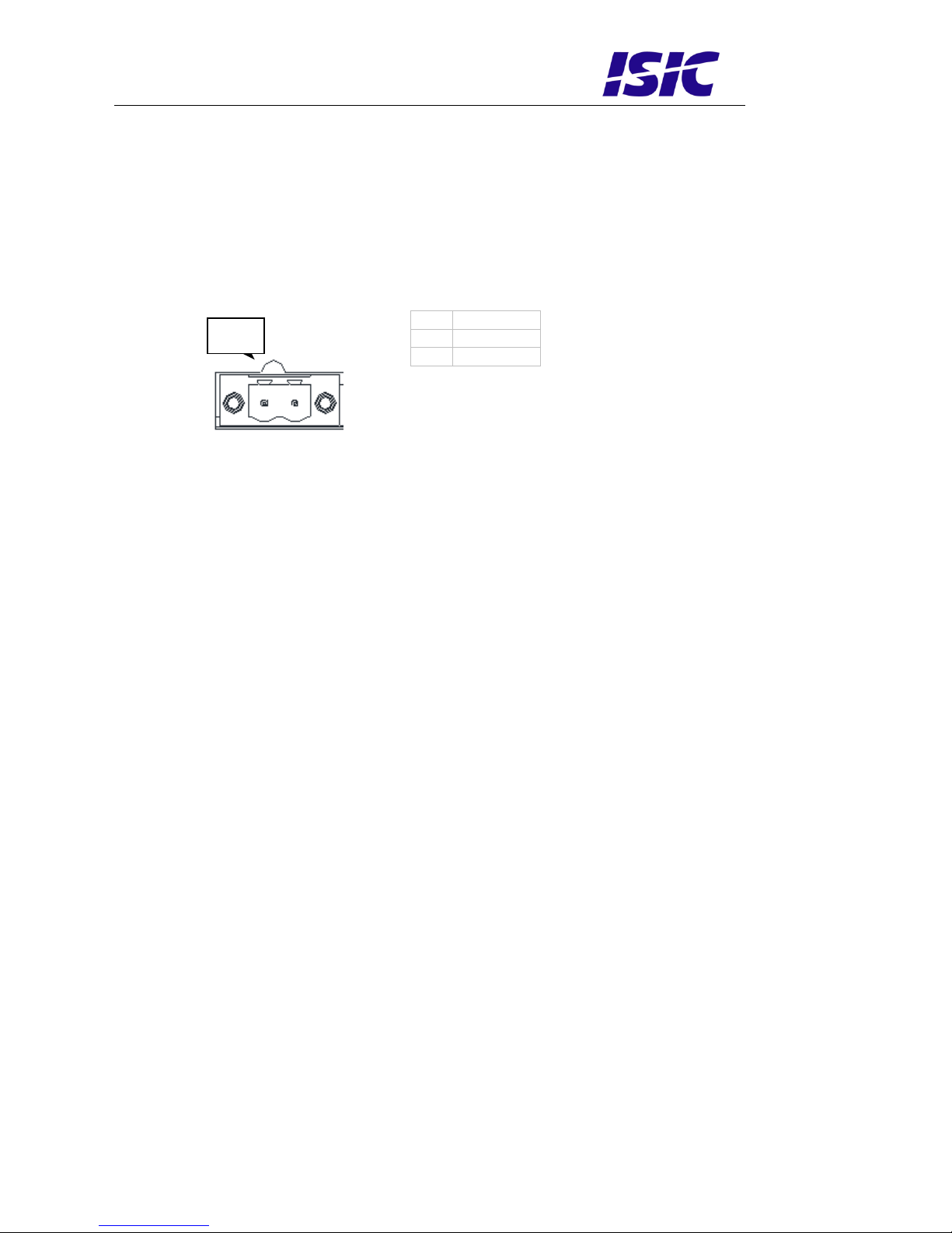
5CONNECTOR PIN-OUT ........................................................................................... 7
6TECHNICAL SPECIFICATIONS DURAPANEL 10.6”.................................................. 8
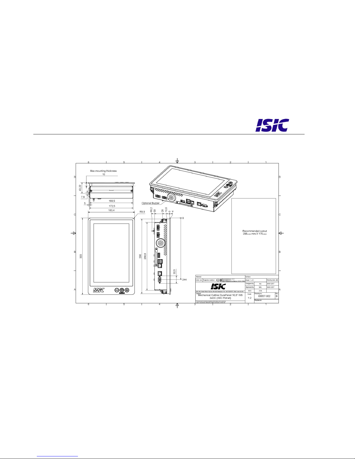
7MECHANICAL OUTLINE DURAPANEL 10.6” ............................................................ 9
7.1 LANDSCAPE.........................................................................................................................................................9
7.2 PORTRAIT ..........................................................................................................................................................10
8BUZZER ............................................................................................................... 11
9DURA COMMUNICATION PROTOCOL ................................................................... 11
9.1 MESSAGE FORMAT ............................................................................................................................................11
9.2 ATTENTION (ATTN)..........................................................................................................................................11
9.3 ADDRESS (ADDR) ............................................................................................................................................11
9.4 MANUFACTURER ID (MAN)..............................................................................................................................12
9.5 MONITOR FIRMWARE VERSION (VER)..............................................................................................................12
9.6 BACKLIGHT LEVEL (BRT).................................................................................................................................12
10 IN RUSH CURRENT .............................................................................................. 13
11 TROUBLESHOOTING............................................................................................ 13
12 SERVICING THE UNIT ......................................................................................... 13
13 ISIC INFO / SUPPORT......................................................................................... 14
14 REVISION HISTORY ............................................................................................ 15
15 APPENDIX A: PIXEL POLICY................................................................................ 16

User Reference Manual –DuraPANEL 10.6”
PN: 08140-000 Rev A Page 4
1Features
Congratulations with your purchase of a DuraPANEL 10.6”. This short form manual is designed
to get you started working with your new DuraPANEL 10.6”.
The DuraPANEL 10.6” is designed for the demanding operating conditions at sea.
The DuraPANEL 10.6” comes with excellent brightness and contrast levels that, together with
wide viewing angles, ensure a good readability thus making it very eye-friendly. For the best
picture quality, always use a double shielded display cable with ferrites.

User Reference Manual –DuraPANEL 10.6”
PN: 08140-000 Rev A Page 5
2General considerations on Installation and
Operation
The DuraPANEL 10.6”is designed to work at conditions according to IEC 60945. However,
keeping the temperature and vibration level at a minimum will extend the life time of the
product. ISIC recommend operating this product at normal room temperature (20-25 °C), with
the lowest level of vibration and humidity.
Installation of the DuraPANEL 10.6”
In order to obtain the best possible operating conditions, please note the following precautions.
-When installing the DuraPANEL 10.6”always use original or identical fittings.
-Room for cooling.
When designing the cabinet/console for the DuraPANEL 10.6”, please ensure that air
can flow freely around the cabinet, in order to avoid any unnecessary rise in
temperature. If it is not possible to have an adequate natural airflow, use a fan to
force the airflow to be higher.
-Mounting positions
To obtain adequate cooling by convection ISIC recommends that the DuraPANEL
10.6”is mounted at least 30 degrees from horizontal. If this is not possible, forced
cooling must be applied directly to the unit in order not to overheat it.
-Sunlight
Avoid direct sunlight to keep temperature low and by that improve lifetime.

User Reference Manual –DuraPANEL 10.6”
PN: 08140-000 Rev A Page 6
3DuraPANEL connections
Below is a view of optional connections to the monitor.
4DuraPANEL front panel controls
The front panel controls are illuminated and will be dimmed continuously depending on
changing of backlight brightness.
Bottoms with symbols + and - :
Used to adjust backlight by pressing + and - .
DIMMING:
This key is used to turn backlight of the display on or off.
UP
DOWN
DIMMING
G
DP
USB 3.0 x 2
LAN1
POWER DC
VGA
LAN2
CF SATA
Optional
Buzzer

User Reference Manual –DuraPANEL 10.6”
PN: 08140-000 Rev A Page 7
Pin1
5Connector pin-out
The nominal input power voltage is 24V (18-36VDC). The input is galvanic isolated and protected against reverse
polarity.
Mating part number: Weidmüller BLZP5.08HC/02/180F
Pin
Power in
1
0VDC
2
24VDC
Pin1

User Reference Manual –DuraPANEL 10.6”
PN: 08140-000 Rev A Page 8
6Technical specifications DuraPANEL 10.6”
DuraPANEL - General
CPU:
Intel®Core® Atom N2600–1,6 GHz 2 cores, 4 threads (CPUMark 525)
Chipset:
Intel®NM10
(Only Windows7 32 bit drivers available)
Memory:
2GB DDR3 800/1066 MHz SODIMM
Hard Disk Drive:
CF SATA or PCI Express Mini Card SSD
Video:
External Video out:
Intel® Graphics controller GMA 3600
DirectX* 9C
VGA and DP ver. 1.1 video output connectors
Ethernet:
2 x 10/100/1000 Gbits/s Ethernet LAN on-board, (RJ45)
Intel© 82583V
USB:
Audio:
2 x USB 2.0 ports
Built-in Buzzer, optimal frequency 3500Hz (Option)
DuraPANEL - Front
Display size:
10.6 inch 16:10 LCD (TFT)
Resolution:
1280 x 800
Active area:
Pixel Pitch:
231 x 139 mm
0.18075 mm x 0.18075 mm
View angle:
89° (T/B), 89° (L/R) (typical)
Luminance:
1000 Cd/m2(typical)
Contrast ratio:
1000:1 (typical)
Front glass:
Anti glare
Touch:
PCAP Multitouch (USB)
DuraPANEL - Power
Standard:
24VDC (18-36VDC)
DuraPANEL - Environmental
Operating Temperature:
-15 to 55 °C
Storage Temperature:
-25 to 70 °C
Relative Humidity:
8 to 95 %
DuraPANEL - Dimensions
Size:
303 (W) x 183,5 (H) x 64,5mm (D)
Weight:
App. 5 kg.
2 page flyer rev. 11.01.2017. Technical specifications are subject to
change without prior notice. For drawing and full technical
specifications please consult the users manual.

User Reference Manual –DuraPANEL 10.6”
PN: 08140-000 Rev A Page 9
7Mechanical outline DuraPANEL 10.6”
7.1 Landscape

User Reference Manual –DuraPANEL 10.6”
PN: 08140-000 Rev A Page 10
7.2 Portrait

User Reference Manual –DuraPANEL 10.6”
PN: 08140-000 Rev A Page 11
8Buzzer
Activate buzzer by sending sinus signal to audio channel.
Optimal frequency is 3500 Hz, sound level is controlled by sound volume adjust.
9Dura Communication protocol
9.1 Message Format
The monitor supports a data rate of 19200 bits per second. Data shall be transmitted with no parity, one start bit, and
one stop bit.
The basic message format is shown below:
ATTN ADDR CMD LEN IHCHK DATA IDCHK
The minimum message length is 7 bytes.
9.2 Attention (ATTN)
This byte identifies the start of a message. The following three values are defined:
ATTN
Description
0x07
Command
0x06
Acknowledge
0x15
Negative Acknowledge
A remote master initiates a command using the 0x07 attention code. The monitor will reply with an acknowledge
(ACK) code if the command was received successfully, or a negative acknowledge (NACK) if the command contained
errors.
Note that the monitor will acknowledge messages, even if it fails to execute the actions contained within. NACKs are
only issued when the message format is corrupted, e.g. invalid checksums.
9.3 Address (ADDR)
This byte is used to identify and address individual monitors. In a multi-slave configuration, the master can target each
monitor individually, in which case the addressed monitor will reply with either an ACK or a NACK.
The remote master can address all monitors simultaneously using the broadcast address. In this case the monitors will
not reply.
ADDR
Description
0x00::0xFE
Individual address space.
0xFF
Broadcast address.

User Reference Manual –DuraPANEL 10.6”
PN: 08140-000 Rev A Page 12
9.4 Manufacturer ID (MAN)
This command shall be sent to the monitor to request Manufacturer ID Code. No data shall be sent with the command
The monitor will reply to this command with an ACK attention code. The DATA field will be set to an ASCII string
with the value “ISIC”
Example:
Ask for the Manufacturer ID:
ATTN
ADDR
CMD
LEN
IHCHK
0x07
0x00
0x4D
0x41
0x4E
0x00
0x1C
Reply from monitor:
ATTN
ADDR
CMD
LEN
IHCHK
DATA
IDCHK
0x06
0x00
0x4D
0x41
0x4E
0x04
0x19
0x49
0x53
0x49
0x43
0xD7
9.5 Monitor Firmware Version (VER)
This command is sent to the monitor to request the Firmware Version of the embedded code. No data shall be sent with
the command.
The monitor will reply to this command with an ACK attention code. The DATA field will be set to an ASCII string
with the ISIC P/N and revision.
Example: 04837-000-D
9.6 Backlight Level (BRT)
This command controls the intensity of the backlight. The backlight level is sent as 1 byte in the DATA field, in the
range of 0x00 to 0xFF; corresponding to minimum and maximum luminance, respectively.
If the checksum is valid, and the command completes successfully, the monitor will reply with an ACK message, with
the current backlight level in the DATA field.
If the checksum was invalid, the monitor will reply with a NACK message. This requirement does not apply to
broadcasted messages.
Example:
Set the Backlight Level to 0xFF:
ATTN
ADDR
CMD
LEN
IHCHK
DATA
IDCHK
0x07
0x00
0x42
0x52
0x54
0x01
0x0F
0xFF
0x00
Reply from Monitor:
ATTN
ADDR
CMD
LEN
IHCHK
DATA
IDCHK
0x06
0x00
0x42
0x52
0x54
0x01
0x10
0xFF
0x00

User Reference Manual –DuraPANEL 10.6”
PN: 08140-000 Rev A Page 13
Power Consumption
Test object / condition
Ptyp [W]
Pmax [W]
DuraPANEL 10.6”
20W
35W
10 In rush current
Test object / condition
[A] @24VDC
DuraPANEL 10.6”
~ 100
11 Troubleshooting
Problem
Cause
Solutions
No picture on display
Backlight level set to off
Increase backlight
Panel PC turned off
Turn on the Panel PC
No power cord connected
Apply power
Buttons on front doesn’t work
No power cord connected
Apply power
The unit smells burned /
smoke is coming from the unit
There might be something
burned inside
Please do not try to open the
unit. Send it to ISIC A/S for
repair.
12 Servicing the unit
In case that the unit still fails after following the troubleshooting send the unit to ISIC for
repair via our RMA service on our web.

User Reference Manual –DuraPANEL 10.6”
PN: 08140-000 Rev A Page 14
13 ISIC info / Support
In case you have inquiries or problems with your DuraPanel 10.6”, you have a number of
possibilities to get support.
Company name:
ISIC A/S
Head office:
Edwin Rahrs Vej 54
DK-8220 Brabrand
Denmark
Shipping address:
Holmstrupgaardvej 5
DK-8220 Brabrand
Denmark
Telephone:
+45 70 20 70 77
Fax:
+45 70 20 79 76
Mail:
mail@isic-systems.com
www:
www.isic-systems.com
VAT number:
DK 16 70 45 39
Bank Name/Address:
Handelsbanken A/S
Havneholmen 29
DK-1561 København V
Denmark
Bank Code:
0892
SWIFT:
HANDDKKK
IBAN for DKK:
DK53 0892 0001 0159 69
IBAN for EUR:
DK48 0892 0003 0026 19
IBAN for USD:
DK26 0892 0003 0026 27
Contacts:
RFQ’s:
By fax to +45 70 20 79 76
By mail to sales@isic-systems.com
Orders:
By fax to +45 70 20 79 76
By mail to orders@isic-systems.com
Support:
Via homepage www.isic-systems.com under aftersales
By mail to service@isic-systems.com
During office-hours (Mo-Th: CET 0800 –1600, Fr: CET 0800 –1500)
at +45 70 20 70 77
Service:
Before shipment for service Request Return Material Authorization
number at homepage www.isic-systems.com under AFTER SALES
TECH SUPPORT RMA
By mail to service@isic-systems.com

User Reference Manual –DuraPANEL 10.6”
PN: 08140-000 Rev A Page 15
14 Revision history
Rev A
January 2017
First release

User Reference Manual –DuraPANEL 10.6”
PN: 08140-000 Rev A Page 16
15 Appendix A: Pixel policy
ISO 9241-307:2008 guidelines for LCD pixel defects
Introduction
TFT displays consist of a set number of pixels. Each pixel consists of 3 sub-pixels also called dots (one red, one blue
and one green). Every sub-pixel is addressed by its own transistor. As a result, the manufacturing of glass substrate is
very complex.
Due to the nature of this manufacturing process, occasional defects can occur. Pixel defects or failures cannot be fixed
or repaired and may occur at any stage during the service life of the TFT display.
To regulate the acceptability of defects and protect the end user, ISIC A/S complies with the ISO 9241-307:2008
standard. This standard recommends how many defects are considered acceptable in a display, before it should be
replaced within the terms of the warranty.
Monitor classification ISO 9241-307:2008
Allowed defects per type per million pixels
Defect classes
Pixel defects
Cluster defect
Type 1
Type 2
Type 3 total
(2xN3a + N3b)
Type 1
Type 2
Type 3
Class: 0
0
0
0
0
0
0
Class: I
1
1
5
0
0
0
Class: II
2
2
10
0
0
1
Class: III
5
15
100
0
0
5
ISIC TFT monitors comply with ISO 9241-307:2008 Class II.
Special agreements about other classifications can be made between ISIC A/S and the customer.
Measurement method/monitoring conditions for pixel defects
In compliance with the ISO-9241-307:2008 standard, the following conditions are observed:
Final check for pixel fault undertaken right after burn-in, i.e. with pre-heating of the display.
Surrounding temperature 25ºC ± 5ºC
Relative air humidity 40–70%
Pixel definition
Every pixel consists of three sub-pixels/dots (red, blue, green).
Every sub-pixel has its own transistor.
The three sub-pixels/dots must be considered as one unit.

User Reference Manual –DuraPANEL 10.6”
PN: 08140-000 Rev A Page 17
Pixel
Pixel defect type 1 Pixel constantly lit Pixel defect type 2 Pixel constantly dark
Pixel defect type 3a Pixel defect type 3b
Sub-pixel/dot (red, blue, green) constantly lit Sub-pixel/dot (red, blue, green) constantly dark
Cluster
A cluster consists of 5 x 5 pixels.
Cluster pixel defect type 1 Cluster pixel defect type 2
Pixels in a cluster area constantly lit Pixels in a cluster area constantly dark
Cluster pixel defect type 3a Cluster pixel defect type 3b
Sub-pixels/dots in a cluster area constantly lit Sub-pixels/dots in a cluster area constantly dark

User Reference Manual –DuraPANEL 10.6”
PN: 08140-000 Rev A Page 18
Pixel faults accepted by ISIC A/S
The maximum number of pixel faults that is considered acceptable at different screen resolutions is shown in the
table below.
This is the native resolution and not the resolution as adjusted by user.
Class II
Allowable number of pixel faults in monitor applications
Screen
type
Native
resolution
Number of
pixels
Pixel defect
type 1
Pixel defect
type 2
Pixel defect
Type 3 total
(2xN3a + N3b)
Cluster
defect type
1 and 2
Cluster
defect
type 3
WVGA
800x480
384,000
0
0
3
0
0
XGA
1024x768
768,432
1
1
7
0
0
WXGA
1280x800
1,024,000
2
2
10
0
1
SXGA
1280x1024
1,310,720
2
2
13
0
1
UXGA
1600x1200
1,920,000
3
3
19
0
1
FHD
1920x1080
2,073,600
4
4
20
0
2
WUXGA
1920x1200
2,304,000
4
4
23
0
2

User Reference Manual –DuraPANEL 10.6”
PN: 08140-000 Rev A Page 19
Edwin Rahrs Vej 54
DK-8220 Brabrand
Denmark
Web: http://www.isic-systems.com
Table of contents
Other ISIC Touch Panel manuals
Popular Touch Panel manuals by other brands

IEI Technology
IEI Technology AFL4-W07-EHL user manual

VIPA
VIPA TP 610C manual

Power-Genex
Power-Genex LSB-3 Series Instructions and operating manual

Kessler-Ellis Products
Kessler-Ellis Products INTELLECT-69PM2 Installation & operating instructions

Kramer
Kramer KT-107S user manual

IEI Technology
IEI Technology 210UPC-V312 user manual