Isotech PHTC-783 Mounting instructions

V 1.11
i
|
P
a
g e
User Operation Manual
PHTC-783
Portable High Temperature Calibrator
Isothermal Technology Limited
Pine Grove, Southport,
Merseyside, PR9 9AG, England
Telephone: +44 (0)1704 543830
Email: [email protected]
Website: www.isotech.co.uk
Isotech North America, Inc
158 Brentwood Drive, Unit #4
Colchester, VT 05446
Phone: +1 (802) 863 8050
Email: [email protected]
Website:
www.isotechna.com

V 1.11
ii
|
P
a
g e
Guarantee
ⓒIsothermal Technology Limited
This instrument has been manufactured to exacting standards and is guaranteed for twelve months against electrical
breakdown or mechanical failure caused through defective material or workmanship, provided the failure is not the result
of misuse.
The warranty period begins on the date of shipment from the manufacturing facility.
In the event of failure covered by this guarantee, the instrument must be returned, carriage paid, to one of the authorized
service centers below for examination and will be replaced or repaired at our option.
Any service work performed after the initial 12-month warranty period, will be warrantied for a period of 60 days,
including replacement and after sales parts.
Fragile ceramic and / or glass parts are not covered by this guarantee.
Interference with or failure to properly maintain this instrument may invalidate this warranty
The company is always willing to give technical advice and assistance where appropriate. Equally, because of the
program of continual development and improvement we reserve the right to amend or alter characteristics and design
without prior notice. This publication is for information only.
Limit of Liability
Isotech’s liability in all cases is limited to the initial purchase price of the instrument. Acceptance and use of this
instrument signify acceptance of this clause and holds harmless, Isothermal Technologies Limited and Isotech North
America Inc. for any and all consequential costs, damages, losses, whether direct or indirect from misuse or failure of the
instrument.
Authorized Service Centers
Isothermal Technology Limited
Pine Grove, Southport,
Merseyside, PR9 9AG, England
Telephone: +44 (0)1704 543830
Email: [email protected]
Website: www.isotech.co.uk
Isotech North America, Inc
158 Brentwood Drive, Unit #4
Colchester, VT 05446
Phone: +1 (802) 863 8050
Email: [email protected]
Website:
www.isotechna.com

V 1.11
iii
|
P
a
g
e
Contents
1.
BEFORE YOU START
1.1. Introduction .................................................................................................................................................................. 1
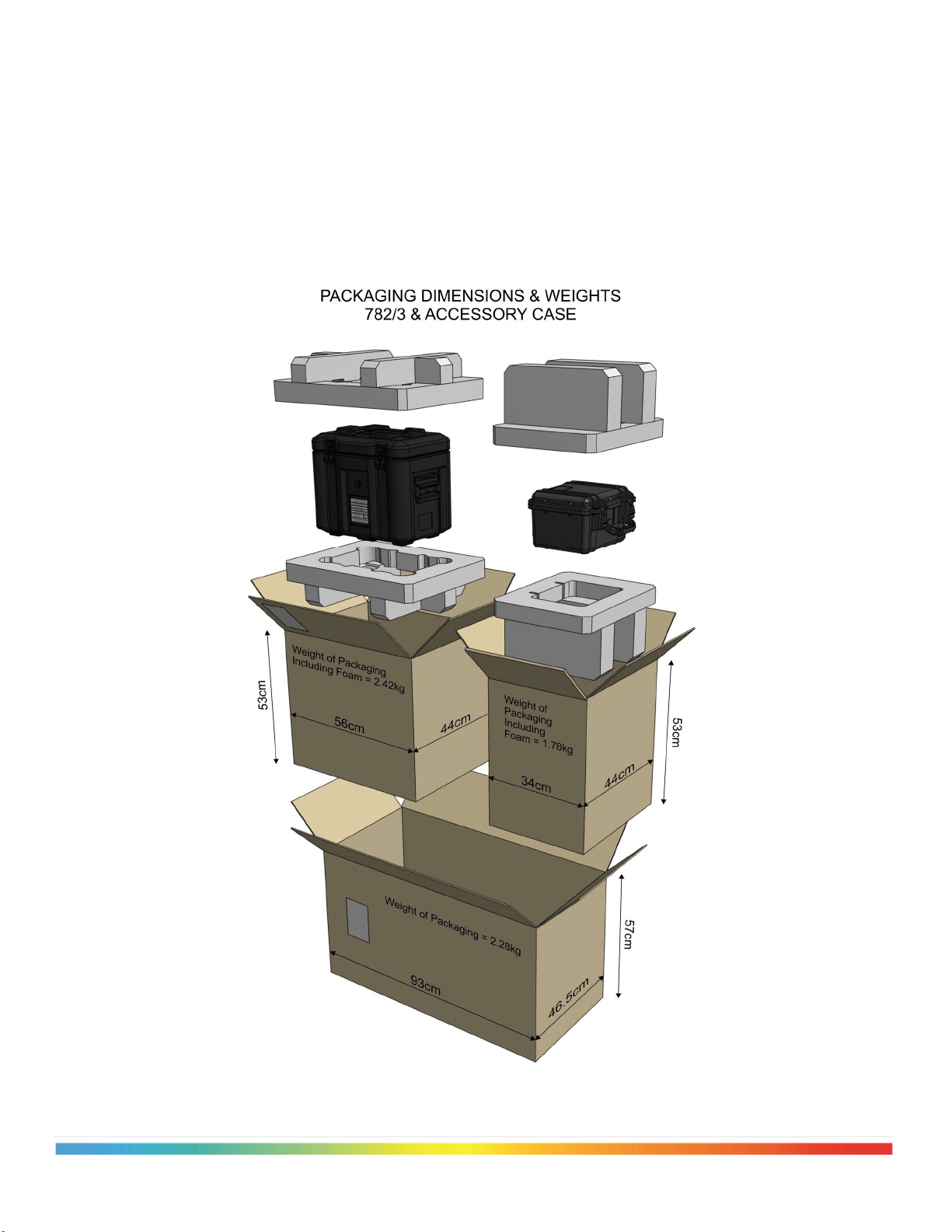
1.2. Unpacking and initial inspection .................................................................................................................................. 2
1.3. Before you use the equipment ...................................................................................................................................... 4
1.4. Summary of symbols and abbreviations used .............................................................................................................. 4
1.5. Electricity supply ......................................................................................................................................................... 5
1.6. The unit must be earthed .............................................................................................................................................. 5
1.7. EMC Information ......................................................................................................................................................... 5
1.8. Cautionary notes. .......................................................................................................................................................... 5
1.9. Safety Warnings ........................................................................................................................................................... 5
1.9.1. Do not modify or disassemble ............................................................................................................................. 5
1.9.2. Beware of electrical considerations ..................................................................................................................... 5
1.9.3. Be careful where it us used .................................................................................................................................. 6
1.9.4. Be careful with extremes of temperature ............................................................................................................. 6
1.9.5. Be careful with removable inserts ....................................................................................................................... 6
1.10. Consider the environment ............................................................................................................................................ 6
2.
QUICK START
2.1. Setting up your PHTC-783 ........................................................................................................................................... 7
2.2. Tour your PHTC-783 ................................................................................................................................................... 8
2.3. Powering up the PHTC-783 ......................................................................................................................................... 9
2.4. Display Information ................................................................................................................................................... 10
2.5. Choosing the Correct Insert ........................................................................................................................................ 11
2.6. Setup Diagram for Probe or Temperature Switch Tests ............................................................................................. 12
2.7. Setting a control Set Point .......................................................................................................................................... 12
3.
THEORY OF OPERATION
3.1. Understanding Dry Well Temperature Calibration .................................................................................................... 13
4.
USING YOUR SYSTEM CAL
4.1. Menu Overview .......................................................................................................................................................... 14
4.2. Switch Info ................................................................................................................................................................. 15
4.3. Setting the Sensor Stem Mode ................................................................................................................................... 15
4.4. Main Menu ................................................................................................................................................................. 15
4.5. Running an Existing Procedure .................................................................................................................................. 16
4.5.1. Using a Switch Procedure .................................................................................................................................. 17
4.5.2. Using a Probe Procedure ................................................................................................................................... 18
4.6. Create, Edit or Delete Procedures .............................................................................................................................. 19
4.6.1. Creating Test Points for a Switch Procedure ..................................................................................................... 19
4.6.2. Creating Test Points for a Probe Procedure ....................................................................................................... 20
4.7. The Settings Menu ..................................................................................................................................................... 21
4.8. The System Menu ...................................................................................................................................................... 21
5.
SPECIFICATIONS .......................................................................................................................................................... 22
6.
REMOTE COMMANDS ................................................................................................................................................. 25
7.
MAINTENANCE
7.1. Taking Care of your PHTC-783 ................................................................................................................................. 28
7.2. Calibration Adjustments ............................................................................................................................................. 28
8.
ACCESSORIES ................................................................................................................................................................ 35
9.
STORAGE AND TRANSPORTATION ......................................................................................................................... 38
10.
APPENDIX ........................................................................................................................................................................ 39

V 1.11
1
|
P
a
g
e
1.
Before You Start
1.1
Introduction
The PHTC-783 portable dry well temperature calibrators are intended to provide an adjustable isothermal environment for
calibration of a variety of temperature sensors and safety switches.
They have been designed under contract for the US Navy.
The isothermal enclosure consists of a fixed thermoelectric or heater block into which removable inserts can be placed.
Temperature sensors requiring calibration are placed in suitably drilled holes in the inserts. A full selection of inserts to
accommodate a variety of sensor diameters is supplied with each PHTC-783.
The main display keeps the operator informed of all pertinent information during the calibration process including; control
set point, well temperature, heating, cooling, or stable condition, thermal switch status, and important user safety
warnings, such as “well touch safe” or “insert too hot to remove”.
A modern interface with unique digital control knob, on-screen alphanumeric keyboard, and traditional membrane keypad
provide new ways to simplify and speed complex operations or data entry.
The PHTC-783 provides users the ability to create, edit, and run, calibration routines to automatically progress through
frequent calibrations of temperature switches or probes. Stored calibration data from the unit under test (UUT) can be
reviewed on the main display or printed directly to a PCL compatible printer via the dedicated USB printer port.
The PHTC-783 has two modes of operation; [Long Stem] which is used for most traditional calibration where the sensor
under test can fit to or near the bottom of the well, and [Short Stem] which changes the calibrator control point to the
midsection of the insert to allow better calibration of short sensors; typically 4” or less.
A unique self-calibration feature allows users to connect an 8.5-digit DMM, such as an Agilent/HP 3458A or Transmille
8104, via the IEEE interface and with an SPRT connected to the DMM the PHTC-783 can run through a 5-point auto
Cal/Adjust process. Traditional manual calibration techniques are included as well.
These Temperature Calibrators are available in two models
PLTC – 782: Portable Low Temperature Calibrator covering -40 to 140°C
PHTC – 783: Portable High Temperature Calibrator covering 38 to 660°C
For questions or support contact your regional service center below.
WORLDWIDE
Isothermal Technology Limited
Pine Grove, Southport,
Merseyside, PR9 9AG, England
Telephone: +44 (0)1704 543830
Email: [email protected]
Website: www.isotech.co.uk
NORTH, CENTRAL & SOUTH AMERICA
Isotech North America, Inc
158 Brentwood Drive, Unit #4
Colchester, VT 05446
Phone: +1 (802) 863 8050
Email: [email protected]
Website:
www.isotechna.com

V 1.11
2
|
P
a
g
e
1.2
Unpacking and Initial Inspection
Our shipping department uses custom designed packaging to safely transport your unit. This packaging consists of
independent shipping boxes with custom polystyrene supports for the main unit and the accessory case, both of which
should be saved for future transport needs.
Despite this specialized packing, accidents can still happen in transit. After unpacking the unit, inspect it for any sign of
shipping damage and confirm that your delivery is in accordance with the check list in Figure 1 “unpacking your PHTC-
783”. If you find any damage or that part of the delivery is missing notify Isotech and the carrier immediately. If the unit
is damaged, you should keep the packing for possible insurance assessment.
Figure 1

V 1.11
3
|
P
a
g
e
Figure 2
What you should have received included with your PHTC-783
1.
PHTC-783 temperature calibrator
2.
Metal identification plate (See Figure 3)
3.
Insert extraction tool
4.
Plastic box with test lead adaptors
5.
Space for up to 6 inserts (not in lid for shipment)
6.
Removable lid assembly
7.
Accessory Case
8.
Layered foam with (4) unique inserts per layer
9.
Operation manual, Test report & Documentation CD
10.
Test Lead - Long
Figure 3

V 1.11
4
|
P
a
g
e
1.3
Before You Use the Equipment
Please read the handbook and familiarize yourself with all warnings, hazards and safety information. Regularly inspect the
equipment, accessories and electrical leads. Do not use if there is any sign of damage. Keep the equipment clean, only use
a damp cloth. Do not use solvents or allow liquids to enter the case.
1.4
Summary of Symbols and Abbreviations
ISO3864 – Caution, read the entire manual before use
IEC 417 – Caution, hot surface (risk of burn)
O
Off
l
On
Waste Electrical and Electronic Equipment (WEEE directive) symbol
Complies with European regulations (CE mark)
USB symbol
Risk of Electrical Shock
The Insert is at a Touch Safe Temperature
The Insert is too hot to touch
The Insert is too cold to touch
UUT Unit Under Test
Stability Indicator
Progressing Indicator

V 1.11
5
|
P
a
g
e
1.5
Electricity Supply
Before connecting to the electricity supply please familiarize yourself with the parts of the manual relevant to your model.
Your unit's supply voltage requirement is specified on a label on the power inlet fuse holder (on/off switch). Only connect
to a power supply matching the requirement stated on the equipment.
1.6
The Unit Must Be Earthed
This equipment is a Class 1 Appliance and must be earthed (grounded). Use the supplied power cord and plug it directly
into an AC outlet with a protective earth. If using an alternative cord, ensure it is of adequate rating.
If fitting a plug to the cable we supplied, the
cable is color coded as follows:
Do not use the equipment if it is not correctly earthed. If in doubt consult Isothermal Technology Ltd or a qualified
electrician.
Always replace accessible fuses only with fuses of exact amperage, voltage, and response time ratings
1.7
EMC Information
This product meets the requirements of the European Directive on Electromagnetic Compatibility (EMC) 89/336/EEC as
amended by EC Directive 92/31/EEC and the European Low Voltage Directive 73/25/EEC, amended by 93/68/EEC. To
ensure emission compliance please ensure that connecting leads are fully screened.
The product meets the susceptibility requirements of EN 50082-1, criterion B.
1.8
Operator Cautionary Note
Operators of this equipment should be adequately trained in the handling of dangerously hot and cold items. It is expected
that personnel using this equipment will be competent with the management of apparatus which will be electrically
powered and under extremes of temperature and are able to appreciate the hazards present and understand the precautions
to be taken with such equipment.
1.9
Safety Warnings
1.9.1
Do Not Modify or Disassemble
•
This instrument was designed specifically for calibration of thermometers and thermal switches. Do not
use the apparatus for jobs other than those for which it was designed.
•
There are no user serviceable parts inside. Do not dismantle or modify the apparatus. For repair
information contact your authorized service center.
•
For equipment with fans, the fan should be kept free from dust build up; a soft brush or vacuum cleaner
may be used on the external grill while at ambient temperatures.
1.9.2
Beware of Electrical Considerations
•
The equipment is for installation category II (transient voltages) and pollution degree II in accordance
with IEC 664 at altitudes to 2000 meters
•
Thermostat test inputs should be voltage free: isolate from any voltage source during test
Color
Function
Green/yellow
Earth
(Ground)
Brown
Live
(line)
Blue
Neutral

V 1.11
6
|
P
a
g
e
1.9.3
Be Careful Where It Is Used
•
The equipment is not for use in hazardous areas or in an environment close to flammable materials or
gases
•
The equipment must be used on a flat level surface, with adequate space around it for air flow and avoid
blocking ventilation slots
•
Ensure free space above the unit to avoid risk of burn or fire
•
The equipment should be used indoors, if used outside ensure ambient temperature is between 0-50°C
(32-122°F) and 0% to 90% RH (non-condensing).
•
Orientate the calibrator in a way that allows easy access to the power switch, and to allow the cable to be
disconnected
•
Avoid excessive heat, humidity, dust and vibration. Ensure it will not be subjected to dripping or
splashing liquids
1.9.4
Be Careful with Extremes of Temperature
•
In normal use the calibration volume, inserts and probes can become very hot and present a burn hazard
•
Do not remove inserts, probes or handle the equipment when it is hot or cold
•
Allow the equipment and accessories to reach a temperature between ambient and 70°C before switching
off or storing the equipment in its case
•
Do not use the equipment outside its recommended temperature range
•
Operating the equipment at extremes of temperature for extended periods may call for early replacement
of the heating or cooling assembly
1.9.5
Be Careful with Inserts
•
Only use inserts supplied with, or ordered specifically for this model
•
Do not handle inserts while they are very hot or cold
•
Inserts for low temperature models may melt and cause a fire if used in high temperature models
•
Only use Isotech inserts which are specially treated to avoid them from becoming stuck in the calibration
volume
•
Do not use powders, liquids or compounds in the insert; this may lead to the insert or probes becoming
stuck
1.10
Consider the Environment
The equipment should be recycled or disposed of in a proper way, following the Waste Electrical and Electronic
Equipment (WEEE) directive

V 1.11
7
|
P
a
g
e
2.0
Quick Start
We know you are eager to use your new PHTC-783 Temperature Calibrator. This 7-step quick start will guide you
through proper steps to Safely begin using the calibrator in the shortest amount of time.
Step 1.
Step 2.
Step 3.
Step 4.
Step 5.
Step 6.
Step 7.
Setup a safe working area – Refer to section 1.9.3
Understand the physical layout of your PHTC-783
Power on your PHTC-783
Understand the safety information on the display
Choose the correct insert
Insert and connect the UUT Probe or Thermal Switch
Set your first temperature set point / or run an existing procedure
2.1
Setting up a Safe Work Area (Quick Start Step 1)
The PHTC-783 must be used on a flat level surface, with adequate space around it for air flow and avoid blocking
ventilation slots
Keep your work area free of clutter; remember dangerous temperatures can be present during operation
Ensure free space above the unit to avoid risk of burn or fire, and allow easy insertion and extraction of test sensors
Orientate the calibrator in a way that allows easy access to the power switch, and to allow the cable to be disconnected
Avoid excessive heat, humidity, dust and vibration
Ensure it will not be subjected to dripping or splashing liquids
The equipment is not for use in hazardous areas or in an environment close to flammable materials or gases
Figure 4

V 1.11
8
|
P
a
g
e
2.2
Tour Your PHTC-783 (Quick Start Step 2)
Figure 5
Getting to Know your PHTC-783
1. Power Inlet – IEC Socket
Use only supplied power cord or one of equivalent
specification.
8. Membrane Keypad
Used to enter numeric values and change units from °F/°C
DO NOT use anything other than your finger to operate the
keypad.
2. Fuse Holder
Use or replace fuses only with fuses of exact amperage,
voltage
and speed
ratings. 4A
anti
-
surge
3. On/Off Switch 9. Primary Display
Refer to section 2.4 for detailed display information.
4. Thermal Switch Inputs
Connect switch test leads here. This input will measure a
resistive short only (Switch Closure), ensure no voltage or
current
is
present
on
the
connections.
10. Calibration Volume for Removable Inserts
Use the supplied extraction tool to insert and remove inserts
Select the calibration inserts closest in diameter to the sensor
under
test.
5. Membrane Function Selection Arrows
** The PHTC-783 is not touch screen **
These membrane keys will select the displayed function on
the screen, which will change depending on the present menu
11. GPIB / IEEE Interface
This port is for advanced users to connect a DMM for
automatic recalibration of the PHTC-783.
6. USB Data Port / Printer Interface
This port is for advanced users to update firmware and
connect a PCL compatible printer for sending test reports
directly from the PHTC-783.
12. USB Communication Interface
This port is for advanced users to remotely control the
PHTC-783.
7. Digital Control Knob
Rotate to increase or decrease numeric values or scroll
through the alphanumeric screen keypad.
Pressing will function as a selection or enter when
appropriate
13. “Dry Out” indicator.
This LED will illuminate during startup if the internal
temperature of the PHTC-783 is too cold for safe operation
to full specification

V 1.11
9
|
P
a
g
e
2.3
Powering on Your PHTC-783 (Quick Start Step 3)
Upon Power on, the PHTC-783 will progress through sequence of 4 screen displays before being ready for user
intervention. A blank display at stage 2, for 5 seconds is a normal part of the power on sequence.
The PHTC-783 will always power up with a control set point of 38°C or 100.4°F to ensure safe operation on
startup or after loss of power. The temperature units °C/°F will remain in the last state selected before powering
down.
RED LED ILLUMINATED? – Notification of Dry Out Period
Special note on environmental conditions before and during power up.
The PHTC-783 is designed to conform to specified
performance and accuracy requirements after being
stored or shipped from -22°F (-30°C) to 160°F (71°C)
and 0% to 100% relative humidity.
However, after storage or shipping in extreme
conditions of greater than 90% humidity and/or low
temperatures where condensation is likely, the PHTC-
783 requires an energized dry-out period prior to full
operation.
Your PHTC-783 has a built-in environmental control
for operating temperature. Essentially, if the
temperature inside the case is below 10°C, it will not
fully power up and only a small fan assisted heater is
energized. This disables at 30°C when the case and
contents are warm and dry enough to allow the
equipment to fully power on. This could take up to 2
hours. During this process a red LED illuminated will
notify the user the PHTC-783 is in a drying out period.
Figure 6
Like all electrical instruments, if the unit is, or has been wet, take appropriate actions to remove moisture prior
to applying power.

V 1.11
10
|
P
a
g
e
2.4
Display Information (Quick Start Step 4)
Figure 7
Primary
Display
Information
(Manual
Control)
1. Well Status Indicator
Quickly indicates temperature status of the inserts, and if
they are safe to touch or not
6. Temperature Limits
Displays programmed Min and Max temperature control
limits for the PHTC-783. Used to protect sensors and
switches not capable of the full range of the PHTC-783
2. Heating / Cooling Indication 7. Safety Warning Display
Can Display a variety of user safety information in
Green
(Safe)
and
Red
(Warning)
text.
3. Stability Progress Indication
Heating or cooling in progress
PHTC-783 is Stable
8. Well Status - Text version of the Icon indicator (2)
4.
Switch
Status
Indication
9.
Control
Set
Point
5.
Switch
Activation
Temperatures
10.
Well
Measured
Temperature

V 1.11
11
|
P
a
g
e
Figure
8
2.5
Choosing the correct insert “reducing sleeve” (Quick Start Step 5)
Proper selection of inserts is critical for accurate temperature calibrations.
Each insert is etched with the suggested probe diameter for use, including
multi-hole inserts and specialty inserts such as the D573 “Flow Gator” sleeve.
Select the insert with internal diameter closest to the diameter of the sensors to be
tested. If unsure the diameter of the UUT, use a dial caliper to make an accurate
measurement.
Ensure that the probe and insert are clean, and the probe can slide freely in and out of the insert without
becoming lodged.
Use the supplied extraction tool to place and remove insert sleeves. The extraction tool, Figure 8, has two ends,
one 90° bend for use with large bore inserts as in Figure 9 and the other end has a M4 thread for tapped inserts
as shown in Figure 10.
Insert Extraction Tool
Figure 9 Figure 10

V 1.11
12
|
P
a
g
e
2.6
Insert the Temperature probe or switch to be calibrated (Quick Start Step 6)
Set up for Thermal Switch Test Set up for Temperature Probe Test
Figure 11 Figure 12
2.7
Setting a Control Set Point (Quick Start Step 7)
There are three ways to enter a new manual control set point.
•
Type the desired value on the keypad and press enter
•
Rotate the digital control knob to enter a new temperature and push the knob
•
Press the [PRESETS] selection arrow and select one of the predefined set points
To run an existing automated procedure, refer to section 4.5

V 1.11
13
|
P
a
g
e
3
Theory of Operation
3.1
Understanding Dry Well Temperature Calibration
The Need for Calibration
At a fundamental level all thermometers need to be characterized or calibrated. Although your own needs to
calibrate are probably more practical, such as maintaining safety, process consistency, or energy efficiency.
No thermometer will remain entirely constant. Thermometers and sensors such as Thermocouples (T/C),
Thermistors, Resistance Thermometers (RTD) or (PRT) change their characteristics with time, temperature
cycling, mechanical shock or they can become contaminated. Without routine calibration you do not truly know
the performance of your temperature sensors.
There is a need to calibrate to meet Quality Standards as well as Safety Standards, (i.e. over temp safety
switches) which in some industries and military branches may be vital to safeguard life.
Calibration can improve efficiency, often if a thermometer’s characteristics are known more accurately savings
in cost can be made. The requirement to calibrate temperature sensors continues to grow. To calibrate a
temperature sensor, it must be subjected to know thermal conditions over a working temperature range, thus the
need for your PHTC-783 Portable Temperature Calibrators!
Temperature indicators are often checked and calibrated with electrical simulators which are connected to the
instrument’s sensor input. The device can then be rapidly checked by programming the equivalent
“temperature” input into the indicator. However, the temperature sensor will have the potential for larger drift,
so it is very important to test and calibrate the temperature sensor with a heat source. If the sensor can be
calibrated while connected to the instrument, then the entire measurement loop can be calibrated.
Dry Block Calibrators
Dry Blocks have a metal block into which the temperature sensors to be calibrated are placed. The block is
heated or cooled to the desired temperature. The Dry Block typically has a large well into which a removable
metal block or “insert” can be placed. This gives good flexibility and accurate results.
Using Dry Block Calibrators
The devices to be calibrated will be placed into the calibration volume, utilizing an appropriate reducing sleeve
to ensure good thermal contact with the UUT. In the most basic configuration, the units under test could be
compared to the display of the temperature controller. For simple testing and low accuracy requirements this
method is adequate.
Typical configurations of the PHTC-783 are shown in the preceding Section 2.6 (figures 11 & 12)

V 1.11
14
|
P
a
g
e
4.0
Using your PHTC-783
4.1
Graphical Full Menu Overview
Figure 13

V 1.11
15
|
P
a
g
e
4.2
Switch Info
Press the [SW INFO] selection arrow from the main display to open or close the switch info display, which shows the
status of the thermal switch inputs and the last recorded open [O:] and closed [C:] temperatures.
4.3
Setting the Stem Mode
Press the [SET STEM] selection arrow from the main display to change the stem mode of the PHTC-783. There is visual
indication on the main display to show which Stem Mode the calibrator is currently in.
In most cases the calibrators will be used in Long Stem Mode. This is the traditional dry block calibration mode where the
sensors being tested can fit to or near the bottom of the calibration well and provides sufficient immersion of the test
sensor for accurate calibration.
The Navy has specific needs for calibrating short stem sensors such as Weksler 2” dial thermometers which cannot reach
the bottom of the calibration well. Short Stem mode changes the control point of your PHTC-783 to the mid-section of the
well to provide more accurate calibrations of short stem sensors. Short Stem mode should be used when your test sensor is
less than 4” in length
4.4
Main Menu
Press the [MENU] selection arrow from the main display to enter submenu levels where more advanced features of the
PHTC-783 reside. Each submenu will be explained in detail in subsequent sections of this manual
Parameter
Description
of
this
specific
parameter
Manual Control This selection functions the same as [BACK] and returns you to the primary
display
for
manual block
control.
Run a Procedure Enters a submenu system to run existing procedures, enter UUT
information,
and
review
or
print
UUT
calibration
data
Stored
Calibrations
A
list
of
previous
calibrations
will
appear
to
load,
view,
and
print
Procedure
Management
Enters
a
submenu
system
to
create,
edit,
delete
or
import/export
procedures
Settings Menu
password-protected menu
Allows the user to set PHTC-783 date, time, Test Report numbers, default
temperature
units
(°C/°F)
and change
the
advanced
level
password
System Menu
password-protected menu
Contains menus to recalibrate the PHTC-783, Reference PRT setup, GPIB
Address, updating the firmware of the PHTC-783 and to view or print the
full
system configuration.

V 1.11
16
|
P
a
g
e
4.5
Running an Existing Procedure
To run an existing procedure from the primary display press [MENU] then [RUN PROCEDURE]
A menu of existing procedures will appear. Select the procedure you wish to run, and the first procedure mode menu
appears.
By selecting [UUT / TEST INFORMATION] you will be presented a menu where you can enter the information related
to the specific UUT you are calibrating such as serial number, test date, test interval, calibrating technician and
environmental conditions if required. This information will appear on the Test Report print out.
Once UUT information is entered you can select [START FIRST RUN]. At this point the procedure display will appear
and the PHTC-783 will cycle through the predefined test points written into the procedure.
At any point during a calibration run you can press [MENU] to return to the procedure menu to
•
View the summary of the existing calibration
•
Abort the calibration run
•
Save and exit the calibration, a file save name will be assigned
By Selecting [VIEW TEST SUMMARY] you will be presented an onscreen
summary of the existing procedure including
Nominal Test Temperatures
First Run Results
Second Run Results
Pass / Fail Status
If you are connected via the USB Data Port to a PCL compatible printer, by
selecting the [PRINT] selection arrow, you can print a complete test report
directly from the PHTC-783.
A full-page test report sample is in Appendix

V 1.11
17
|
P
a
g
e
4.5.1
Using an Existing Switch Procedure
To run an existing SWITCH procedure, setup the switch and
PHTC-783 as shown, then go through the preliminary steps in
section 4.5 above.
Once you select [START FIRST RUN] the switch procedure
display (Figure 14) below will appear. This display keeps the
operator informed of each step of the preprogrammed switch
procedure.
Figure 14
The procedure will now run through the following sequence
1.
Set the calibrator to the starting test as outlined in the procedure
2.
Once the calibrator reaches the start temp, it may or may not wait for stability depending on the
procedure settings
3.
The PHTC-783 will then ramp through the expected (nominal) switch temperature as a rate
programmed into the procedure.
4.
At each step increment, you will hear a clicking noise as if you manually adjusted the set point.
5.
Once the Switch inputs see a contact closure, the PHTC-783 will notify the user via an audible
double beep as well as a “Switch Actuation” display on the screen.
6.
The value will be recorded, and PHTC-783 will display the summary report information on screen
7.
At this point the PHTC-783 will control to the programmed “Finish Temperature” in the procedure
which will be in a safe operating range
8.
Returning to the [Menu] the operator can now print the report, save and exit or abort the run
discarding the results
Table of contents
Other Isotech Test Equipment manuals

Isotech
Isotech MEDUSA 510 Series Operating instructions

Isotech
Isotech IIT 1500 User manual

Isotech
Isotech ITS-90 Operating instructions

Isotech
Isotech ISIS Operating instructions

Isotech
Isotech LCR 1705 User manual

Isotech
Isotech Quick-Cal Series User manual

Isotech
Isotech ICM A7 User manual

Isotech
Isotech PEGASUS PLUS 1200 Series User manual

Isotech
Isotech Saturn 878 Operating instructions

Isotech
Isotech 875 Operating instructions