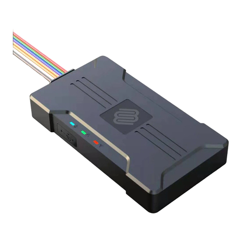
iStartek VT140 User manual

File Name
VT140 User Manual
Ver.
1.0
Update
2021-01-12
Page
1of 11
Copyright Notice ©Shenzhen iStartek Technology Co., Ltd. All rights reserved
iStartek Vehicle GPS Tracker
VT140 User Manual
V1.0

File Name
VT140 User Manual
Ver.
1.0
Update
2021-01-12
Page
2of 11
Copyright Notice ©Shenzhen iStartek Technology Co., Ltd. All rights reserved
Content
1. Copyright and Disclaimer................................................................................................................................... 3
2. Product Description..............................................................................................................................................3
3. Product Function...................................................................................................................................................3
4. Product Specification...........................................................................................................................................4
5. Products and accessories....................................................................................................................................4
5.1 Standard accessories................................................................................................................................ 4
5.2 Optional accessories.................................................................................................................................5
6. Product Appearance.............................................................................................................................................5
7. Product Operation................................................................................................................................................ 6
7.1 Recharge...................................................................................................................................................... 6
7.2 Install SIM card...........................................................................................................................................6
7.3 Turn on Device............................................................................................................................................6
7.4 Parameter Configration........................................................................................................................... 6
7.5 Track by GPS Tracking Platform............................................................................................................ 7
8. Product Installation.............................................................................................................................................. 8
8.1 Power Cable Function Introduction..................................................................................................... 8
8.2. Power Connection.................................................................................................................................... 9
8.3 Digital inputs installation........................................................................................................................ 9
8.4 Analog Input Installation...................................................................................................................... 10
8.5 Output Control Wire Installation........................................................................................................10
8.6 Temperature Sensor Installation.........................................................................................................11
8.7 Ultrasonic Fuel Sensor Installation.....................................................................................................11

File Name
VT140 User Manual
Ver.
1.0
Update
2021-01-12
Page
3of 11
Copyright Notice ©Shenzhen iStartek Technology Co., Ltd. All rights reserved
1. Copyright and Disclaimer
Shenzhen iStartek Technology Co., Ltd. All rights reserved Copyright © 2021 iStartek.
iStartek and are registered trademarks of Shenzhen iStartek Technology Co., Ltd.
This manual cannot be copied for any purpose, disseminated in any way without the written authorization of
iStartek.
iStartek shall not be liable for direct, indirect or all losses (including but not limited to economic losses, personal
injuries, property and assets) caused by the use or inappropriate use of the product or documents.
2. Product Description
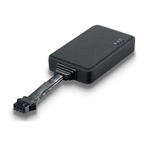
VT140 is a 2G based GPS vehicle tracker that complies with India's AIS140 requirements. Built-in IRNSS positioning
module, reporting location and vehicle status to the vehicle tracking platform through 2G network for real-time
vehicle monitoring, anti-theft and scheduling management. It can be applied to fleet management, public
transportation management, school bus management, taxi operation management, insurance vehicle
management, lease management and private car anti-theft, etc.
The VT140 has a built-in 64Mb Flash memory. When the device enters a place without network, it will
automatically save the historical positioning data. When the network returns to normal, it will automatically
reissue the historical positioning data to the service platform.
VT140 contains 2 RS232 ports, which can be connected to optional accessories to achieve corresponding
functions.
3. Product Function
GPS+GSM base station dual-mode positioning
Real-time tracking
Track by time interval
SOS alarm
SOS button remove alarm
External power failure alarm
Low battery alarm
Low battery alarm
Engine and door status change alarm
Support dual servers
Speeding alarm
Harsh acceleration alarm
Harsh deceleration alarm
Harsh turning alarm
Mileage report

File Name
VT140 User Manual
Ver.
1.0
Update
2021-01-12
Page
4of 11
Copyright Notice ©Shenzhen iStartek Technology Co., Ltd. All rights reserved
64 Mb Flash
FOTA upgrade
4. Product Specification
Item
Specification
Size
99 x 54 x 19.5mm
Weight
106g
Input voltage
DC 9 - 100V/1.5A
Waterproof level
IP66
Inbuilt Battery
500mAh/3.7V(High temperature resistant battery)
Average standby power
consumption
65mA/h
Operating hours
33hours in power saving mode and 7.5 hours in normal working mode
Working temperature
-20℃to 80℃
Working humidity
5% to 95%
GSM Bands
850/900/1800/1900MHz
GPS Sensitivity
-165dB
Positioning accuracy
2.5 meter
LED Indicator
2 LED lights indicate GPS/GSM status
GSM antenna
Built-in FPC
GPS antenna
Built-in ceramic antenna(25 X 25 X 4mm)
Flash
64M bit
Sensor
3D accelerometer
Switch
External toggle switch
SIM card
Nano SIM card,external push-push type
I/O
4 Digital inputs(Can be configured as high and low level trigger mode)
2 Analog input(0~36V)
2 Outputs
1 1-wire
2 RS232
1 5V output wire
1 Micro USB
5. Products and accessories
5.1 Standard accessories

File Name
VT140 User Manual
Ver.
1.0
Update
2021-01-12
Page
5of 11
Copyright Notice ©Shenzhen iStartek Technology Co., Ltd. All rights reserved
Main Unit
5.2 Optional accessories
Ultrasonic Fuel Sensor Capacitive Fuel Sensor 12V/24V Relay
USB Cable Buzzer
6. Product Appearance

File Name
VT140 User Manual
Ver.
1.0
Update
2021-01-12
Page
6of 11
Copyright Notice ©Shenzhen iStartek Technology Co., Ltd. All rights reserved
7. Product Operation
7.1 Recharge
When using V200 for the first time, please connect the tracker's red wire (positive) and black (ground wire) to a
12V or 24V power supply and charge for at least 2 hours to ensure sufficient power. After configuration and
testing are completed, install it on the vehicle.
7.2 Install SIM card
Please make sure that the SIM card has sufficient balance, the GPRS function has been activated and the correct
APN of the SIM card has been confirmed;
Please make sure that the PIN lock function of the SIM card is turned off;
7.3 Turn on Device
Switch ON device or connect to external power supply, VT140 will start up and run.
LED lights indicate operating conditions:
GPS Indicator (Blue)
OFF
Power OFF or in sleep mode
Flash (every 0.1 sec)
GPS module is starting or restarting
Fast Flash (0.1 sec ON, 2.9 sec OFF)
GPS signal received
Slow Flash (1sec ON, 2 Sec OFF)
No GPS signal
GSM Indicator (Green)
ON
There is an incoming call or is in a call
OFF
Device is OFF or in sleep mode
Fast Flash (every 0.1 sec)
GSM module is starting or restarting
Fast Flash(0.1 sec ON, 2.9 sec OFF)
GSM signal received
Slow Flash (1sec ON, 2 Sec OFF)
No GSM signal
7.4 Parameter Configration
Download and install the USB cable driver "PL2303_Prolific_Driver".
After the device is turned on, connect the VT140 to the computer via a USB cable, run the "iStartek Parameter
Editor_V1.00" configuration software and open the port to enter the parameter configuration state.

File Name
VT140 User Manual
Ver.
1.0
Update
2021-01-12
Page
7of 11
Copyright Notice ©Shenzhen iStartek Technology Co., Ltd. All rights reserved
For more parameter configuration, please refer to "iStartek Parameter Editor User Manual".
7.5 Track by GPS Tracking Platform
You can set the server IP, Port, and APN parameters through SMS commands SET PIP、SET PPT、SET SIP、SET SPT、
SET APN and you can also use the iStartek Parameter Editor software to configure related parameters.
For more SMS command functions and parameter configuration, please refer to "VT140 protocol V1.0" and
"iStartek Parameter Editor User Manual".

File Name
VT140 User Manual
Ver.
1.0
Update
2021-01-12
Page
8of 11
Copyright Notice ©Shenzhen iStartek Technology Co., Ltd. All rights reserved
8. Product Installation
8.1 Power Cable Function Introduction
PIN
Color
Function
DC
Red
DC In (power input), connect to the positive pole of the car battery. Input voltage:
9V~100V.
GND
Black
GND, connect to the negative pole of the car battery, or to the iron place on the car.
IN1
Whit
Digital input 1, default is negative trigger. Positive and negative trigger can be
configured by Parameter Editor.
Used to connect to the SOS button.
IN2
Orange
Digital input 2, default is positive trigger. Positive and negative trigger can be
configured by Parameter Editor;
Used for ACC detection
IN3
Grey
Digital input 3, default is positive trigger.
Can configure positive and negative trigger by Parameter Editor.
IN4
Green
Digital input 4, default is positive trigger.
Can configure positive and negative trigger by Parameter Editor.
AD1
Blue
AD1 input, positive trigger and AD1 input (0-36V, 12-bit precision)
AD2
Pink
AD2 input, positive trigger and AD1 input (0-36V, 12-bit precision)
OUT1
Yellow
Open-drain output, drive capacity greater than 500MA;
An external relay can be connected to remotely cut off the car's fuel/engine power
supply, etc.
OUT2
Brown
Open-drain output, drive capacity greater than 500MA;
Can connect an external buzzer to alarm, etc.
1-wire
Purple
Digital, can be connected to iButton and temperature sensor
GND
Black
GND
5V
Red
DC 5V output, available for temperature sensor and serial port accessories.
RX
Green
RS232-1 RX
TX
White
RS232-1 TX
RX
Green
RS232-2 RX

File Name
VT140 User Manual
Ver.
1.0
Update
2021-01-12
Page
9of 11
Copyright Notice ©Shenzhen iStartek Technology Co., Ltd. All rights reserved
TX
White
RS232-2 TX
8.2. Power Connection
Connect the red power wire and black ground wire to the positive and negative pole of the car battery to get
power supply:
8.3 Digital inputs installation
Input2 can be connected to the vehicle ignition to detect ignition status.
Input1, input3 or Input4 can be connected to the car door to detect the state.

File Name
VT140 User Manual
Ver.
1.0
Update
2021-01-12
Page
10 of 11
Copyright Notice ©Shenzhen iStartek Technology Co., Ltd. All rights reserved
8.4 Analog Input Installation
The device can be connected to up to two fuel sensors. The wiring connection is as follows:
8.5 Output Control Wire Installation
The output wire can be connected to an external relay to cut off fuel/electricity and control the vehicle. You can
also connect the buzzer to alarm.

File Name
VT140 User Manual
Ver.
1.0
Update
2021-01-12
Page
11 of 11
Copyright Notice ©Shenzhen iStartek Technology Co., Ltd. All rights reserved
8.6 Temperature Sensor Installation
Connect device to a temperature sensor, the wiring connection is as below:
8.7 Ultrasonic Fuel Sensor Installation
The height measurement range of the ultrasonic fuel sensor is 0~100cm (0~250cm optional), and the
corresponding voltage output range is 0~5V.
VT140 analog input connect to the ultrasonic fuel sensor, the green wire of the ultrasonic sensor is connected to
the AD1 blue wire of the VT200 or the AD2 pink wire.
Example: When the fuel is empty, the sensor output voltage is 0V. With a fuel tank height of 100cm as the
standard, then fuel sensor output voltage is 5V when fuel is full.
If the height of the fuel tank is H0cm and the fuel tank is full of F liters, the fuel sensor output voltage is V=H0/20
when the fuel is full.
Calculate the remaining fuel volume:
Percentage of fuel = (AD/V)*100%
The fuel volume height is: H=(AD/5)*100cm
The remaining liters of fuel volume = (AD/V)*F liters
If you have any other questions, please send an email to in[email protected], we are happy to serve you.
Table of contents
Other iStartek GPS manuals

iStartek
iStartek VT200-L User manual

iStartek
iStartek PT29 User manual

iStartek
iStartek VT600 3G User manual

iStartek
iStartek VT500 User manual

iStartek
iStartek VT206 User manual

iStartek
iStartek VT600 User manual

iStartek
iStartek VT900-L User manual

iStartek
iStartek PT60-L User manual

iStartek
iStartek VT900-E User manual

iStartek
iStartek VT202 User manual
Popular GPS manuals by other brands

Garmin
Garmin GPSMAP 700 Series owner's manual

Hi-Target
Hi-Target Qstar Series Product specification and manual

Alltrack USA
Alltrack USA Plug-In Installation instructions manual

PetTronix
PetTronix ROAMEO SEEKR owner's manual

Pharos
Pharos GPS 135 user manual

Magnavox
Magnavox MX 9112 Installation and service manual