iStartek VT600 User manual

File Name
VT600 User Manual
Version
1.3
Update
2018-03-17
Page
1 of 11
Copyright statement 2018 Shenzhen iStartek Technology Co., Ltd. All right reserve
iStartek GPS Vehicle Tracker
VT600 User Manual
V1.3

File Name
VT600 User Manual
Version
1.3
Update
2018-03-17
Page
2 of 11
Copyright statement 2018 Shenzhen iStartek Technology Co., Ltd. All right reserve
Contents
1. Copyright and Disclaimer..................................................................................................................错误!未定义书签。
2. Product Overview..............................................................................................................................错误!未定义书签。
3. Product Functions.......................................................................................................................错误!未定义书签。
4. Product Specifications...............................................................................................................错误!未定义书签。
5. Hardware and Accessories................................................................................................................错误!未定义书签。
5.1 Standard Accessories......................................................................................................................错误!未定义书签。
5.2 Optional Accessories.......................................................................................................................错误!未定义书签。
6. Product Appearance..........................................................................................................................错误!未定义书签。
7. Product Use ......................................................................................................................................错误!未定义书签。
7.1 Charge ............................................................................................................................................错误!未定义书签。
7.2 Install SIM Card...............................................................................................................................错误!未定义书签。
7.3 Installation of GSM/GPS Antenna ...................................................................................................错误!未定义书签。
7.4 Device Boot.....................................................................................................................................错误!未定义书签。
7.5 Track by Calling...............................................................................................................................错误!未定义书签。
7.6 Track by SMS................................................................................................................................................................8
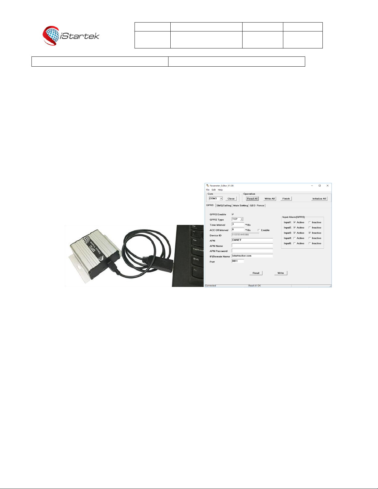
7.7 Parameter Configuration.................................................................................................................错误!未定义书签。
7.8 Track by Platform ............................................................................................................................错误!未定义书签。
8. Product Installation............................................................................................................................错误!未定义书签。
8.1 Introduction of Input/Output Functions ...............................................................................错误!未定义书签。
8.2 Power/Ground Cable Installation...................................................................................................................................9
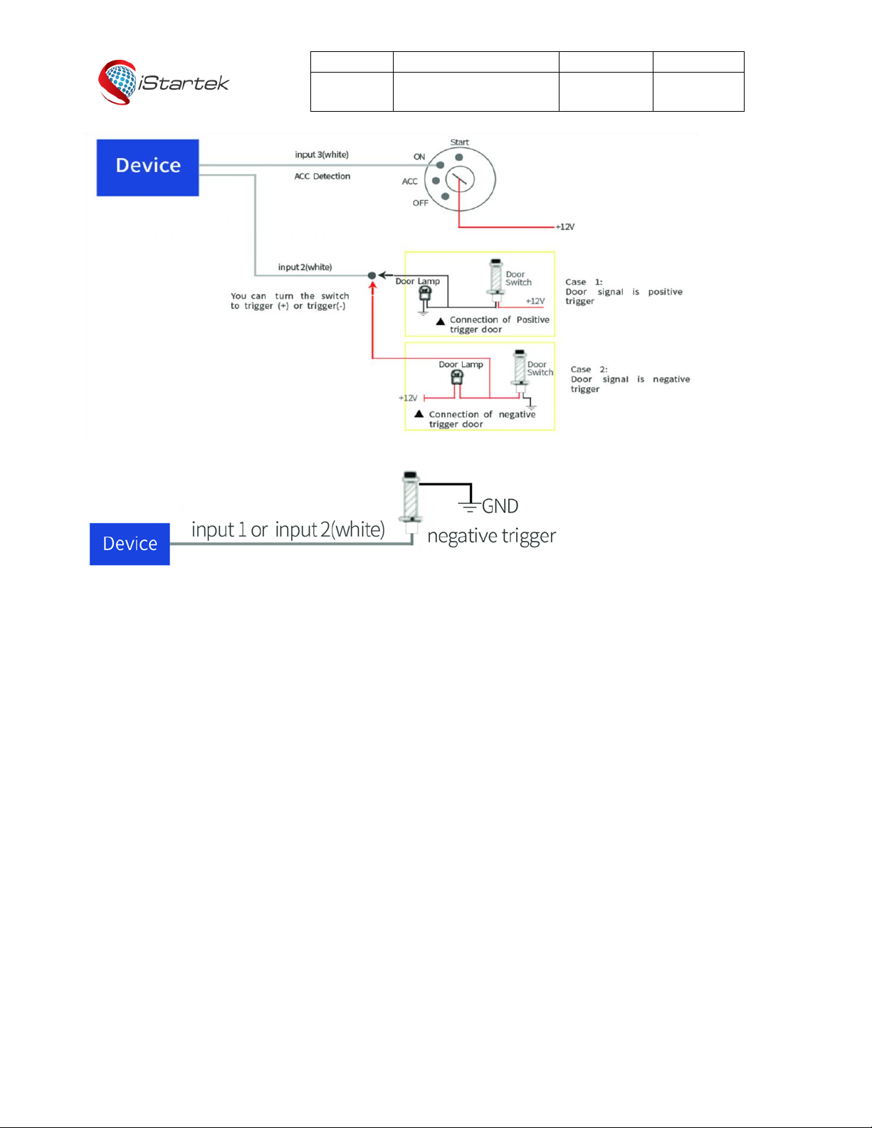
8.3 Digital Input Cable Installation..............................................................................................错误!未定义书签。
8.4 Analog Input (AD1) Installation........................................................................................................错误!未定义书签。
8.5 Output Control Cable Installation.........................................................................................错误!未定义书签。
8.6 Temperature Sensor Installation (Customized)...............................................................错误!未定义书签。
8.7 iButton Installation (Customized).........................................................................................错误!未定义书签。
8.8 Ultrasonic Fuel Sensor Installation......................................................................................错误!未定义书签。

File Name
VT600 User Manual
Version
1.3
Update
2018-03-17
Page
3 of 11
Copyright statement 2018 Shenzhen iStartek Technology Co., Ltd. All right reserve
1. Copyright & Disclaimer
Shenzhen Startrack Technology Co.,LTD All rights reserved © 2018 iStartek.
iStartek & are registered trademarks of Shenzhen iStartek Technology co., LTD
This user manual can not be reproduced for any purpose, disseminated in any way without the written
authorization of iStartek.
iStartek shall not be liable for direct, indirect or all losses (including but not limited to economic losses, personal
injuries, property and assets) caused by the use or inappropriate use of the product or documents.
2. Product Overview
VT600 is a GSM based GPS vehicle tracker, specially developed and designed for fleet management, public
transport management, school bus management, taxi operation management, vehicle insurance company
management, rental management and private car anti-theft, etc.
VT600 has an inbuilt GPS module to obtain accurate position data. This device utilizes its GSM capability to send
position data or vehicle status to tracking server base for tracking and fleet management.
VT600 has built-in 4MB Flash memory. When the device enter a GSM blind area, it will automatically save the
historical location data and resend once GSM signal recovery.
3. Product Functions
1. GPS+LBS Dual Positioning
2. Real-time Tracking
3. Track by Interval
4. Track by Distance
5. Track by Turning
6. Track by SMS
7. SOS Alarm
8. Power-cut Alarm
9. Engine and Door ON/OFF Status Alarm
10. Geo-fencing Alarm
11. Speeding Alarm

File Name
VT600 User Manual
Version
1.3
Update
2018-03-17
Page
4 of 11
Copyright statement 2018 Shenzhen iStartek Technology Co., Ltd. All right reserve
12. GPS Blind Area Alarm
13. Harsh Acceleration Alarm
14. Harsh deceleration Alarm
15. Low Battery Alarm
16. Low External Battery Alarm
17. Mileage Report
18. 4MB Flash Memory
19. OTA
20. ACC ON/Off Time Interval
21. Remote Control of Oil and Electricity
22. Listen-in
23. iButton for Driver Identity Recognition(Optional)
24. Buzzer Alarm(Optional)
25. Fuel Monitoring(Optional)
26. Temperature Monitoring(Optional)
4. Product Specifications
Items
Specification
Size
65x61x26mm
Weight
104g
Power Supply
9-36V/1.5A
Built-in Battery
500mAh/3.7V
Normal Power Consumption
60mAh
Working Time
30 hours in power-saving mode and 7.5 hours in normal mode
Operating Temperature
-20°C to 55°C
Humidity
5% to 95%
Frequency
GSM/GPRS: 850/900/1800/1900Mhz
GPS Sensitivity
-165Db
Position Accuracy
2.5m
LED
2 LED lights to show GPS/GSM status
Antenna
External GPS/GSM Antenna
Flash Memory
4MB(16192 GPRS, 256 SMS)
Sensor
Vibration Sensor
I/O
3 digital inputs (1 negative trigger, 1 positive trigger, 1 positive or negative
optional trigger )
1 analog input (0-6V)
1 output
1 Mic port
1 USB port

File Name
VT600 User Manual
Version
1.3
Update
2018-03-17
Page
5 of 11
Copyright statement 2018 Shenzhen iStartek Technology Co., Ltd. All right reserve
5. Product and Accessories
5.1 Standard Accessories
5.2 Optional Accessories
6. Product Appearance
Unit
Power cord
GPS Antenna
GSM Antenna
USB Cable
Relay
iButton Reader
iButton Key
Ultrasonic Fuel Sensor
Lever Type Fuel sensor
Temp Sensor
GSM antenna connector
GPS antenna connector
ON/OFF Button
USB
Port

File Name
VT600 User Manual
Version
1.3
Update
2018-03-17
Page
6 of 11
Copyright statement 2018 Shenzhen iStartek Technology Co., Ltd. All right reserve
7. Product Use
7.1 Charge
When using VT600 for the first time, please connect the device red wire(positive) and black wire(ground) to 12V
or 24V power supply for at least 2 hours to ensure sufficient power, install it on vehicle after setting and testing.
7.2 Install SIM Card
①The device supports 4G/3G Sim Card with 2G service.
②Make sure that the SIM card has sufficient balance, and has opened GPRS function and obtained the correct
APN of the SIM card.
③Make sure that the PIN code is turned off.
④If you require the function of reporting SMS location after makes a phone call, please ensure that the SIM card
has caller display function.
⑤Make sure the device is OFF before installing SIM card.
A. Unscrew the front baffle screw and remove the PCBA
B. Install SIM Card
C. Install PCBA and screw up the screw
7.3 Installation of GSM/GPS Antenna
①Twist the GSM antenna to “GSM” SMA Connector and GPS antenna to “GPS” SMA connector, make
sure both antennas are tightened and not loosened.
②GSM antenna can be hidden in any place far away from the power supply, can not be pasted on the
metal surface otherwise it will affect the strength of GSM signal.
③GPS antenna have to be installed in open sky place without metal shielding.

File Name
VT600 User Manual
Version
1.3
Update
2018-03-17
Page
7 of 11
Copyright statement 2018 Shenzhen iStartek Technology Co., Ltd. All right reserve
7.4 Device Boot
Hold the ON/OFF button for 3-5 seconds or connect an external power supply, VT600 will turn ON.
LED indicator lights operation status:
GPS LED (Blue)
On
Input is active
OFF
Device is off or in sleep mode
Flashing ( every 0.1 second)
The unit or GPS module is being initialized
Flashing (0.1 second on and 2.9 seconds off)
VT600 has a GPS fix
Flashing (1 second on and 2 seconds off)
VT600 has no GPS fix
GSM LED (Green)
On
A call is coming in or in a call
OFF
Device is off or in sleep mode
Flashing ( every 0.1 second)
The unit or GSM module is being initialized
Flashing (0.1 second on and 2.9 seconds off)
VT600 is connected to the GSM network
Flashing (1 second on and 2 seconds off)
VT600 is not connected to the GSM network
7.5 Track by calling
Make a missed call to the tracker and it will report its location by SMS with the following google link format, click
on the link to display the current location of the device on Google Maps.
SMS Content Description:
142161102222,Current! 20171123 15:53,A,0Km/h,http://maps.google.com/?q=22.540103,114.082329
Content
description
142161102222
Device ID
Current!
Alarm characters, different alarm events have
different alarm characters
20171123 15:53
Date and time, format YYYYMMDD hh: mm
A
GPS positioning status, "A" means GPS valid,
"V" means GPS invalid.
0Km/h
The device velocity is 0 km/h
http://maps.google.com/?q=22.540103,114.082
Google maps link

File Name
VT600 User Manual
Version
1.3
Update
2018-03-17
Page
8 of 11
Copyright statement 2018 Shenzhen iStartek Technology Co., Ltd. All right reserve
329
7.6 Track by SMS
Send SMS W000000,100 to VT600
You will receive a SMS with Google map link, and click on the link to display the current location of the device on
Google maps.
Refer to iStartek SMS Protocol for SMS instructions and more SMS commands.
7.7 Parameter Configurations
Download and install USB cable drive PL2303_Prolific_Driver.
Connect VT600 to PC via USB cable, run Parameter_Editor configuration software and open the port. Press the
ON/OFF button for 1sec to let device enter parameter configuration mode.
Refer to the Guidelines for the Use of Parameter Configuration Software for more parameter configurations
details.
7.8 Tracking by Platform
You can set APN, server IP, Port and TCP/UDP, GPRS interval by SMS commands 011, 012, 013, 014, or you can
use Parameter_Editor software to configure corresponding parameters.
Refer to iStartek SMS Protocol and Guidelines for the Use of Parameter Configuration Software for more
SMS command functions and parameter configurations.
8.Product installation
8.1 Introduction of Input/Output Function

File Name
VT600 User Manual
Version
1.3
Update
2018-03-17
Page
9 of 11
Copyright statement 2018 Shenzhen iStartek Technology Co., Ltd. All right reserve
DC
OUT
AD
GND
GND
IN3
IN2
IN1
PIN
color
functions
DC
Red
DC In (power input). Input voltage: 9V~36V. 12V/24V suggested.
GND
Black
Ground , connect to the negative pole of car battery or to the place where with iron.
IN1
White
Digital input 1, negative trigger;
Connect SOS button by default.
IN2
White
Digital input 2, positive or negative trigger optional, negative trigger by default ;
Can be connected to door trigger line and detect the OPEN/CLOSE status.
IN3
White
Digital input 3, positive trigger;
Can be connected to car ACC and detect ignition ON/OFF status.
OUT
Yellow
Output control.
Low voltage (0V) when effective and open drain when ineffective.
Output open drain sink voltage (ineffective): 45V max.
Output low voltage sink current (effective): 500mAmax.
AD
Blue
10-digit Analog Input. Input voltage: 0~6V
GND
Black
SOS button ground wire
8.2 Power/Ground Cable Installation
Respectively connect the red power cable and the black ground cable to the positive and negative poles of the car
battery to give power supply:
8.3 Digital Input Cable Installation
Input3 can be connected to the “ON” switch to detect the ignition.
Input2 can be connected to the car door to detect OPEN/CLOSE status.

File Name
VT600 User Manual
Version
1.3
Update
2018-03-17
Page
10 of 11
Copyright statement 2018 Shenzhen iStartek Technology Co., Ltd. All right reserve
Input1 or Input2 (Vil trigger) can also be connected to PIN switch to detect the hood status:
8.4 Analog Input Installation
The analog input range is 0-6V, it can be connected to voltage output sensors, such as fuel sensor.
Input Voltage Formula: Input Voltage=(AD*6)/1024
For example, GPRS data is:
094506.000,A,2232.5412,N,11404.6919,E,0.00,,290709,,*12|1.7|110|0000|00AA,0000
AD = 0x00AA = 170
Input Voltage=(AD*6)/1024=(170*6)/1024=0.996V.
Take fuel sensor connection as an example, sensor yellow-green cable is connected to VT600 blue cable.
The output voltage of the sensor is 0V when the oil is empty and 5V when the oil is full.
Calculating the fuel percentage:
Percentage= (ADx6)÷(1024x5)x100%

File Name
VT600 User Manual
Version
1.3
Update
2018-03-17
Page
11 of 11
Copyright statement 2018 Shenzhen iStartek Technology Co., Ltd. All right reserve
8.5 Output Control Cable Installation
The output control cable can be connected to relay for cutting off oil/electricity and controlling the vehicle. Can
also connected to buzzer.
8.6 Temperature Sensor Installation (Customized)
Customized hardware and software versions when the device connect to temperature sensor.
Customizing AD cable to 1-wire cable, IN2 to 5V power supply cable of temperature sensor.
The wiring diagram is as follows:
8.7 iButton Installation (Customized)
Customized hardware and software version when device connect to iButton.

File Name
VT600 User Manual
Version
1.3
Update
2018-03-17
Page
12 of 11
Copyright statement 2018 Shenzhen iStartek Technology Co., Ltd. All right reserve
Customizing AD cable to iButton 1-wire cable, Input2 to Output2 for swiping beep.
Device connect with ibutton can prevent driver start vehicle illegally.
When the driver starts the vehicle without swiping authorized iButton Key, it is considered illegally, the device will
be cut oil and electricity automatically, the vehicle will not start.
Refer to the related parameter setting instructions iStartek SMS Protocol and iStartek GPRS Protocol.
The wiring diagram is as follows:
8.8 Ultrasonic Fuel Sensor Installation
The height measurement range of the ultrasonic fuel sensor is 0-100cm, and the corresponding voltage output
range is 0-5V.
The oil calculating formula: h=(((AD*6)/1024)/5)*100cm
If you have any questions, please send E-mail to us i[email protected]om, we will serve you wholeheartedly !
Other manuals for VT600
1
Table of contents
Other iStartek GPS manuals

iStartek
iStartek PT60-L User manual

iStartek
iStartek VT140 User manual

iStartek
iStartek VT900-L User manual

iStartek
iStartek VT200-L User manual

iStartek
iStartek VT600 3G User manual

iStartek
iStartek VT202 Parts list manual

iStartek
iStartek PT29 User manual

iStartek
iStartek VT900-E User manual

iStartek
iStartek VT900 User manual

iStartek
iStartek VT202 User manual