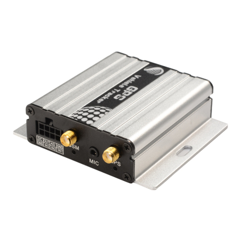
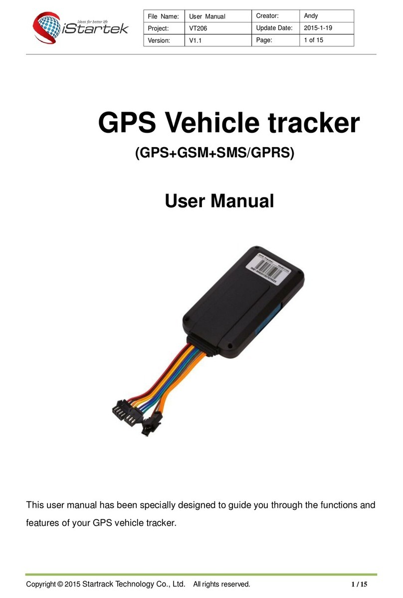
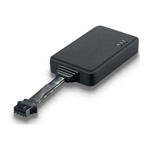
iStartek VT200-L User manual

File Name
VT200-L User Manual
Ver.
1.1
Update
2021-4-10
Page
1of 18
Copyright Notice ©Shenzhen iStartek Technology Co., Ltd. All rights reserved
iStartek 4G Vehicle GPS Tracker
VT200-L User Manual
V1.3

File Name
VT200-L User Manual
Ver.
1.1
Update
2021-4-10
Page
2of 18
Copyright Notice ©Shenzhen iStartek Technology Co., Ltd. All rights reserved
Content
1. Copyright and Disclaimer................................................................................................................................................................ 3
2. Product Description........................................................................................................................................................................... 3
3. Product Function................................................................................................................................................................................ 3
4. Product Specification........................................................................................................................................................................ 4
5. Products and accessories................................................................................................................................................................. 5
5.1 Standard accessories............................................................................................................................................................ 5
5.2 Optional accessories.............................................................................................................................................................6
6. Product Appearance.......................................................................................................................................................................... 7
7. Product Operation............................................................................................................................................................................. 7
7.1 Recharge.................................................................................................................................................................................. 7
7.2 Install SIM card.......................................................................................................................................................................7
7.3 Turn on Device....................................................................................................................................................................... 8
7.4 Track by SMS...........................................................................................................................................................................8
7.5 Parameter configuration..................................................................................................................................................... 9
7.6 Track by GPS Tracking Platform.........................................................................................................................................9
8. Product Installation......................................................................................................................................................................... 10
8.1 Power Cable Function Introduction............................................................................................................................... 10
8.2. Device and Accessories Wire Connection...................................................................................................................11
8.2.1 Power/Ground Wire Connection................................................................................................................................. 12
8.2.2 Digital inputs installation.............................................................................................................................................. 12
8.2.3 Analog Input Installation............................................................................................................................................ 13
8.2.4 Output Control Wire Installation..............................................................................................................................15
8.2.5 Temperature Sensor Installation..................................................................................................................................16
8.2.6 RFID Reader Installation................................................................................................................................................ 16
8.2.7 iButton Installation..........................................................................................................................................................18
8.2.8 Ultrasonic Fuel Sensor Installation............................................................................................................................. 19
8.2.9 OBD Reader Installation................................................................................................................................................ 21
8.2.10 Speed limiter installation............................................................................................................................................ 21

File Name
VT200-L User Manual
Ver.
1.1
Update
2021-4-10
Page
3of 18
Copyright Notice ©Shenzhen iStartek Technology Co., Ltd. All rights reserved
1. Copyright and Disclaimer
Shenzhen iStartek Technology Co., Ltd. All rights reserved Copyright © 2021 iStartek.
iStartek and are registered trademarks of Shenzhen iStartek Technology Co., Ltd.
This manual cannot be copied for any purpose, disseminated in any way without the written authorization of
iStartek.
iStartek shall not be liable for direct, indirect or all losses (including but not limited to economic losses, personal
injuries, property and assets) caused by the use or inappropriate use of the product or documents.
2. Product Description
VT200-L is a 4G based GPS vehicle tracker. With built-in high-precision GPS positioning module reports the
vehicle location and vehicle status to the vehicle tracking service platform through the 4G network for real-time
vehicle monitoring, anti-theft, and dispatch management. It can be applied to fleet management, public
transportation management, school bus management, taxi operation management, vehicle insurance company
management, leasing management and private car anti-theft, etc.
VT200-L has a built-in 128Mb Flash memory. When the device enters blind area, it will automatically save historical
positioning data. When the network recover, it will automatically resend historical positioning data to the service
platform.
VT200-L contains an RS232 port, which can be connected to RFID to perform identity recognition and vehicle
control for vehicle drivers; It can also be connected to OBD reader to read car ECU data and other RS232
peripherals to achieve corresponding functions.
3. Product Function
GPS+GSM base station dual-mode positioning
Real-time tracking
Track by time interval
Track by distance
Heading change report
Mileage report
External power failure alarm
SMS alarm
SOS alarm
Low battery alarm
Engine and door status change alarm
Support dual servers
Geo-fence alarm
Speeding alarm
GPS signal loss alarm

File Name
VT200-L User Manual
Ver.
1.1
Update
2021-4-10
Page
4of 18
Copyright Notice ©Shenzhen iStartek Technology Co., Ltd. All rights reserved
Harsh acceleration alarm
Harsh deceleration alarm
Harsh turning alarm
Impact alarm
Vibration (towing) alarm
Idling alarm
Fatigue driving alarm
Fuel theft alarm
Low fuel alarm
High and low temperature alarm
128 Mb Flash
FOTA upgrade
Set ACC ON, ACC OFF time interval
Remote control fuel/electricity
RFID, iButton driver identification (optional)
Buzzer alarm (optional)
Fuel sensor (optional)
Temperature sensor (optional)
OBD reader (optional)
4. Product Specification
Item
Specification
Size
99 x 54 x 19.5mm
Weight
106g
Input voltage
DC 9 - 100V/1.5A
Waterproof level
IP66
Inbuilt Battery
500mAh/3.7V(High temperature resistant battery)
Average standby power
consumption
110mA/h
Operating hours
33hours in power saving mode and 4.5 hours in normal working mode
Working temperature
-20℃to 80℃
Working humidity
5% to 95%
LTE/WCDMA/GSM Bands
VT200-LCN:
LTE-FDD: B1/B3/B5/B8
LTE-TDD: B34/B38/B39/B40/B41
GSM: 900/1800MHz
VT200-LEU
LTE-FDD: B1/B3/B5/B7/B8/B20/B28
LTE-TDD: B38/B40/B41
GSM: 850/900/1800/1900MHz

File Name
VT200-L User Manual
Ver.
1.1
Update
2021-4-10
Page
5of 18
Copyright Notice ©Shenzhen iStartek Technology Co., Ltd. All rights reserved
VT200-LAU
LTE-FDD: B1/B2/B3/B4/B5/B7/B8/B28/B66
LTE-TDD: B40
WCDMA:B1/B2/B4/B5/B8
GSM: 850/900/1800/1900MHz
GPS Sensitivity
-165dB
Positioning accuracy
2.5 meter
LED Indicator
2 LED lights indicate GPS/GSM status
GSM antenna
Built-in FPC
GPS antenna
Built-in ceramic antenna(25 X 25 X 4mm)
Flash
128M bit
Sensor
3D accelerometer
Switch
External toggle switch
SIM card
Nano SIM card,external push-push type
I/O
3 Digital inputs(Can be configured as high and low level trigger mode, Input3 can
be configured as AD mode)
1 Analog input(0~36V)
2 Outputs
1 1-wire
1 RS232
1 5V output wire
1 Micro USB
1 Speaker
1 Microphone
5. Products and accessories
5.1 Standard accessories
Main Unit

File Name
VT200-L User Manual
Ver.
1.1
Update
2021-4-10
Page
6of 18
Copyright Notice ©Shenzhen iStartek Technology Co., Ltd. All rights reserved
5.2 Optional accessories
RFID Card Reader RFID Tag iButton Reader iButton
Ultrasonic Fuel Sensor Capacitive Fuel Sensor Temperature Sensor 12V/24V Relay
OBD Reader USB Cable Buzzer Speaker
Microphone SOS Button

File Name
VT200-L User Manual
Ver.
1.1
Update
2021-4-10
Page
7of 18
Copyright Notice ©Shenzhen iStartek Technology Co., Ltd. All rights reserved
6. Product Appearance
7. Product Operation
7.1 Recharge
When using V200 L for the first time, please connect the tracker's red wire (positive) and black (ground wire) to a
12V or 24V power supply and charge for at least 2 hours to ensure sufficient power. After configuration and
testing are completed, install it on the vehicle.
7.2 Install SIM card
The device supports 2G/3G/4G SIM card;
Please make sure that the SIM card has sufficient balance, the GPRS function has been activated and the correct
APN of the SIM card has been confirmed;
Please make sure that the PIN lock function of the SIM card is turned off;
If you need to use the function: Call to reply location, please make sure that the SIM card has the caller ID display
function;
Please make sure the device is turned off before installing SIM.
A. Remove the waterproof rubber plug;
B. Install the SIM card in the correct direction.

File Name
VT200-L User Manual
Ver.
1.1
Update
2021-4-10
Page
8of 18
Copyright Notice ©Shenzhen iStartek Technology Co., Ltd. All rights reserved
7.3 Turn on Device
Switch ON device or connect to external power supply, V200 L will start up and run.
LED lights indicate operating conditions:
GPS Indicator (Blue)
OFF
Power OFF or in sleep mode
Flash (every 0.1 sec)
GPS module is starting or restarting
Fast Flash (0.1 sec ON, 2.9 sec OFF)
GPS signal received
Slow Flash (1sec ON, 2 Sec OFF)
No GPS signal
GSM Indicator (Green)
ON
There is an incoming call or is in a call
OFF
Device is OFF or in sleep mode
Fast Flash (every 0.1 sec)
GSM module is starting or restarting
Fast Flash(0.1 sec ON, 2.9 sec OFF)
GSM signal received
Slow Flash (1sec ON, 2 Sec OFF)
No GSM signal
7.4 Track by SMS
Send SMS command to VT200-L:
0000,800
You will receive a text message with a link to Google maps. Click to open the link to display the current location on
Google maps.
Please refer to "iStartek GPS Tracker Communication Protocol V1.3" for the description of SMS content and
more SMS commands

File Name
VT200-L User Manual
Ver.
1.1
Update
2021-4-10
Page
9of 18
Copyright Notice ©Shenzhen iStartek Technology Co., Ltd. All rights reserved
7.5 Parameter configuration
Download and install the USB cable driver "PL2303_Prolific_Driver".
After the device is turned on, connect the VT200-L to the computer via a USB cable, run the "iStartek Parameter
Editor_V1.01" configuration software and open the port to enter the parameter configuration state.
For more parameter configuration, please refer to "iStartek Parameter Editor User Manual V1.5".
7.6 Track by GPS Tracking Platform
1. You can set the server IP, Port, and APN parameters through SMS commands 100, 102, and 109, and you can
also use the iStartek Parameter Editor software to configure related parameters.
2. Check the parameters of commands 100, 101, 102, 105, 106, and 109 through SMS command 808, and you can
also use iStartek Parameter Editor software to configure related parameters.
For more SMS command functions and parameter configuration, please refer to "iStartek GPS tracker
Communication Protocol V1.3" and "iStartek Parameter Editor User Manual V1.5".

File Name
VT200-L User Manual
Ver.
1.1
Update
2021-4-10
Page
10 of 18
Copyright Notice ©Shenzhen iStartek Technology Co., Ltd. All rights reserved
8. Product Installation
8.1 Power Cable Function Introduction
PIN
Color
Function
DC
Red
DC In (power input), connect to the positive pole of the car battery. Input voltage:
9V~36V. 12V/24V suggested.
GND
Black
GND, connect to the negative pole of the car battery, or to the iron place on the car.
IN1
Whit
Digital input 1, default is negative trigger. Positive and negative trigger can be
configured by Parameter Editor.
Used to connect to the SOS button.
IN2
Orange
Digital input 2, default is positive trigger. Positive and negative trigger can be
configured by Parameter Editor;
Used for ACC detection.
IN3
Grey
Digital input 3, default is positive trigger.
Can configure positive and negative trigger or AD2 input (0-6.6V, 12-bit precision) by
Parameter Editor.
AD1
Blue
AD1 input, positive trigger and AD1 input (0-36V, 12-bit precision) can be configured
by Parameter Editor.
OUT1
Yellow
Open-drain output, drive capacity greater than 500MA;
An external relay can be connected to remotely cut off the car's fuel/engine power
supply, etc.
OUT2
Brown
Open-drain output, drive capacity greater than 500MA;
Can connect an external buzzer to alarm, etc.
1-wire
Purple
Digital, can be connected to iButton and temperature sensor, can support up to 8
temperature sensors.
GND
Black
GND
5V
Red
DC 5V output, available for temperature sensor and serial port accessories.
RX
Green
RS232 RX
TX
White
RS232 TX
Speaker-
Yellow
External speaker, two-way conversation.

File Name
VT200-L User Manual
Ver.
1.1
Update
2021-4-10
Page
11 of 18
Copyright Notice ©Shenzhen iStartek Technology Co., Ltd. All rights reserved
Speaker+
Orange
Mic+
Brown
External MIC, two-way conversation or listening.
Mic-
Grey
8.2. Device and Accessories Wire Connection

File Name
VT200-L User Manual
Ver.
1.1
Update
2021-4-10
Page
12 of 18
Copyright Notice ©Shenzhen iStartek Technology Co., Ltd. All rights reserved
8.2.1 Power/Ground Wire Connection
Connect the red power wire and black ground wire to the positive and negative pole of the car battery to get
power supply:
8.2.2 Digital inputs installation
Input2 can be connected to the vehicle ignition to detect ignition status.
Input1 or Input3 can be connected to the car door to detect the state.

File Name
VT200-L User Manual
Ver.
1.1
Update
2021-4-10
Page
13 of 18
Copyright Notice ©Shenzhen iStartek Technology Co., Ltd. All rights reserved
8.2.3 Analog Input Installation
The range of analog input AD1 is 0-36V, and the range of AD2 is 0-6.6V. Two voltage output sensors such as fuel
sensors can be connected. The wiring connection is as follows:

File Name
VT200-L User Manual
Ver.
1.1
Update
2021-4-10
Page
14 of 18
Copyright Notice ©Shenzhen iStartek Technology Co., Ltd. All rights reserved
After connected wires, can set the size of the fuel tank (length, width, height), sensor type (capacitive fuel sensor
or ultrasonic fuel sensor), liters of fuel stolen, fuel stolen time, low fuel alarm by Parameter Editor.

File Name
VT200-L User Manual
Ver.
1.1
Update
2021-4-10
Page
15 of 18
Copyright Notice ©Shenzhen iStartek Technology Co., Ltd. All rights reserved
For example, as above parameters setting, if the fuel tank connected to AD1 decreases more than 20 liters within
60 seconds, an fuel theft alarm will be generated; and if the fuel volume is less than 10 liters, a low fuel alarm will
be generated.
Example: The fuel tank height is 100cm and full fuel is 50 liters, GPRS data as below:
&&A147,021104023195429,000,0,,180106093046,A,22.646430,114.065730,8,0.9,54,86,76,326781,460|0|27B3|0EA
7,27,0000000F,02,01,04E2|018C|01C8 |0000,1,0104B0,01013D|02813546\r\n
AD1 voltage is 0x01C8 (hexadecimal)=456 (decimal), AD1=456/100 (fixed value)=4.56V;
AD2 voltage is 0x0000=0,AD2=0/100=0V;
Example: Connect the GPS Tracker analog input to capactive fuel sensor, the yellow-green wire of the sensor are
connected to the blue wires (AD) of the VT200-L.
When the fuel is empty, the sensor output voltage is 0V, when the fuel is full, the sensor output voltage is 5V
Calculate the percentage of remaining fuel:
Fuel percentage=(AD/5)*100%=(4.56/5)*100%=91.2%.
Calculate the remaining fuel in liters:
The remaining fuel in liters = (AD/5) * 50 liters = 45.6 liters
8.2.4 Output Control Wire Installation
The output wire can be connected to an external relay to cut off fuel/electricity and control the vehicle. You can
also connect the buzzer to alarm.

File Name
VT200-L User Manual
Ver.
1.1
Update
2021-4-10
Page
16 of 18
Copyright Notice ©Shenzhen iStartek Technology Co., Ltd. All rights reserved
8.2.5 Temperature Sensor Installation
Connect device to a temperature sensor, the wiring connection is as below:
After connected wires, the temperature sensor can be configured through SMS commands, set high and low
temperature alarms, and collect temperature value. For related parameter setting instructions, please refer to
"iStartek GPS tracker Communication Protocol V1.3".
Example: after connected a temperature sensor as shown above,
1) Configure temperature sensor, can send command: 0000,135,1,Storage room
Description: 1 is the serial number of the temperature sensor, and Storage room is the name of the temperature
sensor.
2) Set high and low temperature alarms, you can send commands: 0000,136,1,40.5,-10
Description: 1 is the serial number of the temperature sensor, 40.5℃ is the high temperature alarm, and -10℃ is
the low temperature alarm.
3) Get the temperature value, you can send the command: 0000,137
Reply: 137, 1: 29.0, 2: 28.8
Description: 1 is the first temperature sensor with a temperature value of 29.0°C; 2 is the second temperature
sensor with a temperature value of 28.8°C.
8.2.6 RFID Reader Installation
When the device is connected to an RFID card reader, it can prevent illegal starting of the vehicle. The wiring
connection is as follows:
When the driver does not swipe the authorized card to start the vehicle, it is considered to be illegally started, the
device will automatically disconnect the fuel supply and electricity, and the vehicle cannot be started.
For related parameter setting instructions, please refer to "iStartek GPS tracker Communication Protocol V1.3".

File Name
VT200-L User Manual
Ver.
1.1
Update
2021-4-10
Page
17 of 18
Copyright Notice ©Shenzhen iStartek Technology Co., Ltd. All rights reserved
After connected wires as above, you can authorize the RFID card, delete the RFID card, and query the
authorization status of the RFID card according to the SMS instructions.
Example: to authorize an RFID card, you can send SMS command: 0000,144,123456789,987654321
Description: The authorization ID number is 123456789,987654321.
After authorization, set OUT1 to control vehicle fuel and electricity supply. When OUT1 is required to control the
fuel and electricity supply, it is necessary to use the 212 command to set the 53 event to control OUT1. Swiping
the card to control the fuel and electricity is a separate control logic, not controlled by the output mode set by 251
command.
Commands that can be sent: 0000, 212, 1, 1, 53
To delete the RFID card, you can send the SMS command: 0000,145,123456789,987654321
Delete the ID number 123456789,987654321.
Description: To query the authorization status of the RFID card, you can send the SMS command:
0000,146,123456789,987654321
Query ID number 123456789,987654321,
SMS reply 146,123456789:1,987654321:1
Description: 1 means authorized (authorization status: 0 means not authorized, 1 means authorized).

File Name VT200-L User Manual Ver. 1.1
Update 2021-4-10 Page 18 of 18
Copyright Notice ©Shenzhen iStartek Technology Co., Ltd. All rights reserved
8.2.7 iButton Installation
When the device is connected to an iButton, it can prevent illegal starting of the vehicle. The wiring connection is
as follows:
When the driver does not swipe the authorized button to start the vehicle, it is considered to be illegally started,
the device will automatically disconnect the fuel supply and electricity, and the vehicle cannot be started.
For related parameter setting instructions, please refer to "iStartek GPS tracker Communication Protocol V1.3".
After connected wires as above, you can authorize the iButton ID, delete the iButton ID, and query the
authorization status of the iButton ID according to the SMS instructions.
Example: to authorize an iButton ID, you can send SMS command: 0000,144,#00000A678C,#00000E4321F
Description: The authorization ID number is 0x00000A678C,0x00000E4321F.
After authorization, set OUT1 to control vehicle fuel and electricity supply. When OUT1 is required to control the
fuel and electricity supply, it is necessary to use the 212 command to set the 53 event to control OUT1. Swiping
the button to control the fuel and electricity is a separate control logic, not controlled by the output mode set by
251 command.
Commands that can be sent: 0000, 212, 1, 1, 53
When use the ibutton function, Output2 is defaulted as the card swiping prompt tone. A beep sound will be heard
when the iButton is swiped.
To delete the iButton ID, you can send the command: 0000,145,#00000A678C,#00000E4321F
Delete the ID number 0x00000A678C,0x00000E4321F
Description: To query the authorization status of the iButton ID, you can send the command:
0000,146,#00000A678C,#00000E4321F
Query ID number 0x00000A678C,0x00000E4321F

File Name
VT200-L User Manual
Ver.
1.1
Update
2021-4-10
Page
19 of 18
Copyright Notice ©Shenzhen iStartek Technology Co., Ltd. All rights reserved
SMS reply 146,#00000A678C:1,#00000E4321F:1
Description: 1 means authorized (authorization status: 0 means not authorized, 1 means authorized).
8.2.8 Ultrasonic Fuel Sensor Installation
The height measurement range of the ultrasonic fuel sensor is 0~100cm (0~250cm optional), and the
corresponding voltage output range is 0~5V.
V200 L analog input connect to the ultrasonic fuel sensor, the green wire of the sensor is connected to the AD1
blue wire of the VT200-L or the IN3 gray wire (AD2).
Example: When the fuel is empty, the sensor output voltage is 0V. With a fuel tank height of 100cm as the
standard, then fuel sensor output voltage is 5V when fuel is full.
If the height of the fuel tank is H0cm and the fuel tank is full of F liters, the fuel sensor output voltage is V=H0/20
when the fuel is full.
Calculate the remaining fuel volume:
Percentage of fuel = (AD/V)*100%
The fuel volume height is: H=(AD/5)*100cm
The remaining liters of fuel volume = (AD/V)*F liters
After connected wires, can set the size of the fuel tank (length, width, height), sensor type (capacitive fuel sensor
or ultrasonic fuel sensor), liters of fuel theft alarm, fuel theft time, low fuel alarm by Parameter Editor.
1) Configuration by Parameter Editor: Set the fuel tank name to Right Tank; Fuel tank type to ultrasonic fuel
sensor; Fuel tank size, 1000mm in length, 500mm in width, and 1000mm in height; Set the fuel theft alarm to
active when the fuel reduction exceeds 20 liters within 60 seconds; Set low fuel alarm to active when the fuel
volume is less than 10 liters.

File Name
VT200-L User Manual
Ver.
1.1
Update
2021-4-10
Page
20 of 18
Copyright Notice ©Shenzhen iStartek Technology Co., Ltd. All rights reserved
2) Configuration by SMS Command: Set fuel tank parameters through SMS commands 138, 139, 140, and
141. For related parameter setting commands, please refer to "iStartek GPS tracker Communication Protocol
V1.3".
Send above parameters by SMS commands:
Set fuel tank parameters, you can send commands: 0000,138,1,1000,500,1000
Description: 1 is the serial number of the fuel tank. The length of the fuel tank is 1000mm, the width is 500mm, and
the height is 1000mm.
Set the type of fuel sensor, you can send commands: 0000,139,1,1,Right Tank
Description: The first "1" is for the serial number of the fuel tank, the second "1" is AD1 connected to ultrasonic
fuel sensor, and Right Tank is the name of the fuel tank.
Set the fuel theft alarm, you can send commands: 0000,140,1,20,60
Description: Set AD1 as the corresponding fuel tank, and the fuel theft alarm will be triggered when the fuel
reduction exceeds 20 liters within 60 seconds.
Set low fuel alarm, you can send commands: 0000,141,1,10
Description: Set AD1 as the corresponding fuel tank, and a low fuel alarm will be triggered when the fuel volume is
less than 10 liters.
Note: The 138, 139, and 141 commands must be set to detect fuel alarms.
For example: GPRS data with a fuel tank height of 100cm and a full fuel of 50 liters
&&A147,021104023195429,000,0,,180106093046,A,22.646430,114.065730,8,0.9,54,86,76,326781,460|0|27B3|0EA
7,27,0000000F,02,01,04E2|018C|01C8 |0000,1,0104B0,01013D|02813546\r\n
AD1 voltage is 0x01C8 (hexadecimal)=456 (decimal), AD1=456/100 (fixed value)=4.56V;
AD2 voltage is 0x0000=0, AD2=0/100=0V;
Fuel percentage=(AD1/5)*100%=(4.56/5)*100%=91.2%
Fuel height: H=(AD1/5)*100cm=(4.56/5)*100cm =91.2 cm
The remaining fuel volume in liters = (AD1/5) * 50 liters = 45.6 liters
Table of contents
Other iStartek GPS manuals

iStartek
iStartek VT900-E User manual

iStartek
iStartek VT140 User manual

iStartek
iStartek VT202 User manual

iStartek
iStartek VT900 User manual

iStartek
iStartek VT600 3G User manual

iStartek
iStartek VT100-L User manual

iStartek
iStartek VT600 User manual

iStartek
iStartek VT900-G User manual

iStartek
iStartek VT206 User manual

iStartek
iStartek VT500 User manual
Popular GPS manuals by other brands

Konlen
Konlen KL-P103 user manual

Spidertracks
Spidertracks Spider X installation manual

SubSurface Instruments
SubSurface Instruments PL-2000 Quick reference guide

Teltonika
Teltonika Telematics FMB150 First start-up quick start guide

SPK Electronic Co
SPK Electronic Co SPK-TRACKER-PET01 manual

AVITON
AVITON AZ281MA user manual