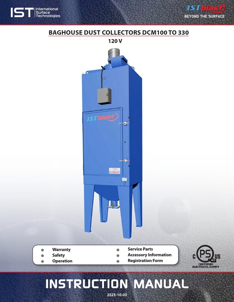
ISTblast DCM600 User manual

INSTRUCTION MANUAL
2022-04-01
T
he
reference
in
surface
TreaTmenT
International
Surface
T
echnologies
istsurface.com
www.istsurface.com
Warranty
Safety
Operation
Service Parts
Accessory Information
Registration Form
CARTRIDGE DUST COLLECTORS DCM600 TO 1800
120 V

T
he
reference
in
surface
TreaTmenT
International
Surface
T
echnologies
istsurface.com
2
DCM600 to 1800 - Instruction Manual
TABLE OF CONTENTS
Page
NOTICE TO PURCHASERS INTRODUCTION..............................................................................................................3
USE AND EQUIPMENT MAINTENANCE GENERAL SAFETY RULES PERSONAL SAFETY.........................4
SPECIFICATIONS HOW IT WORKS ...............................................................................................................................5
GENERAL DESCRIPTION....................................................................................................................................................6
INSTALLATION.......................................................................................................................................................................7
INSTALLATION CONT’D...................................................................................................................................................8
DRAINING DUST OPERATION ADJUSTMENTS......................................................................................................9
CARTRIDGE DUST COLLECTOR GENERAL PARTS LIST......................................................................................10
FAN MOTOR & SUCTION HOSE......................................................................................................................................11
MUFFLERS...............................................................................................................................................................................12
DIAGRAMS MOUNTING CARTRIDGES......................................................................................................................13
CARTRIDGE MEDIA.............................................................................................................................................................14
PREVENTIVE MAINTENANCE SCHEDULE...................................................................................................................15
DCT1000 TIMER CONTROLLER PERIODICAL ADJUSTMENTS ..................................................................16 TO 18
OPTIONAL HEPA FILTER SPECIFICATIONS LIST................................................................................................. 19, 20
IMPELLERS & MUFFLER.....................................................................................................................................................21
CLOGGING SYSTEM............................................................................................................................................................22
ELECTRICAL BOX SOLENOIDE VALVES.....................................................................................................................23
TROUBLESHOOTING..........................................................................................................................................................24
PREVENTIVE MAINTENANCE CARTRIDGES: REPLACEMENT, CLOGGING, CLEANING............................25
PNEUMATIC DIAGRAM.......................................................................................................................................................26
ELECTRICAL SCHEMATICS........................................................................................................................................ 27 TO 31
SEQUENTIAL CONTROLLER...................................................................................................................................... 32 TO 48
ISTBLAST LIMITED WARRANTY ....................................................................................................................................49
ISTBLAST WARRANTY REGISTRATION........................................................................................................................50
INFORMATION TECHNICAL ASSISTANCE..................................................................................................................51
ABOUT THE COMPANY.....................................................................................................................................................52

T
he
reference
in
surface
TreaTmenT
International
Surface
T
echnologies
istsurface.com
3
DCM600 to 1800 - Instruction Manual
The products described in this material, and the information relating to those products, is intended for
knowledgeable, experienced users of abrasive blasting equipment.
No representation is intended or made as to the suitability of the products described herein for any particular
purpose of application. No representations are intended or made as to the eciency, production rate, or the
useful life of the products described herein.
Any estimate regarding production rates or production nishes are the responsibility of the user and must
be derived solely from the user’s experience and expertise, and must not be based on information in this
material.
The products described in this material may be combined by the user in a variety of ways for purposes
determined solely by the user. No representations are intended or made as to the suitability or engineering
balance of the combination of products determined by the user in his selection, nor as to the compliance
with regulations or standard practice of such combinations of components or products.
It is the responsibility of the knowledgeable, experienced users of the products mentioned in this material to
familiarize themselves with the appropriate laws, regulations and safe practices that apply to these products,
equipment that is connected to these products and materials that may be used with these products.
It is the responsibility of the user to insure that proper training of operators has been performed and a safe
work environment is provided.
Our company is proud to provide a variety of products to the abrasive blasting industry, and we have
condence that the professionals in our industry will utilize their knowledge and expertise in the safe
ecient use of these products.
NOTICE TO PURCHASERS AND USERS OF OUR PRODUCTS
AND THIS INFORMATIONAL MATERIAL
1. Carefully inspect the shipping carton for any signs of transport damage. The damage to the carton often
indicates possibility of transport damage to the equipment inside.
2. Carefully remove your ISTblast dust collector from the shipping carton and skid.
3. Check your equipment immediately to ensure that it is free of transport damage. Report any transport
damage to the carrier without delay for possible claim procedures. ISTblast is not responsible for damage to
equipment after it leaves our warehouse.
4. Check the equipment received and compare it with the parts you have received. If any parts are missing,
contact the supplier you purchased the equipment from.
Before operating the ISTblast dust collector, read this Instruction Manual completely. All ISTblast products are
engineered and manufactured to the highest performance standards and have been subjected to detail testing
before shipment from the factory.
Welcome to the ISTblast® family of sandblasting products.This booklet contains helpful information
and acquaints you with the operation and maintenance of your equipment. Please read carefully
and follow our recommendations to assure trouble free operation. If you have any questions, please
do not hesitate to contact your distributor or our technical service.
INTRODUCTION

T
he
reference
in
surface
TreaTmenT
International
Surface
T
echnologies
istsurface.com
4
DCM600 to 1800 - Instruction Manual
GENERAL SAFETY RULES
PERSONAL SAFETY
USE AND EQUIPMENT MAINTENANCE
•KEEP WORK AREA CLEAN.
• KEEP CHILDREN AWAY. Do not let visitors come in contact with the equipment. All visitors should
be kept away from the work area.
•GUARD AGAINST ELECTRIC SHOCK. Non-skid footwear is recommended where damp or wet ground
may be encountered. A ground fault circuit interrupter protected power line must be used for these
conditions.
•DRESS PROPERLY. Do not wear loose clothing or jewelry. They can be caught in the moving parts. Wear
protective hair covering to contain long hair.
•USE SAFETY EQUIPMENT. WEAR SAFETY GOGGLES or glasses with side shields.
•WEAR A DUST PROOF MASK.
•STAY ALERT. USE YOUR COMMON SENSE. Concentrate on what you are doing. Do not operate the unit
when you are tired or under the inuence of drugs or alcohol.
•DO NOT OVERREACH. Keep proper footing and balance at all times.
•BEFORE CONNECTING THE UNIT to an electric current, make sure that the current is the same as
that indicated on the identication plate of the collector. An electric current higher than indicated
that could seriously injure the user and also damage the collector. If you have any doubts, do not
connect the unit.
•DO NOT FORCE THE EQUIPMENT. It will perform better and more safely if It will perform according to
the manufacturer’s specications and without hazards
•USE OF ANY OTHER ACCESSORIES not specied in this manual may be dangerous.
•DISCONNECT THE UNIT on its maintenance.
•DO NOT ALTER OR IMPROPERLY USE THE UNIT. These units are precision equipment. Alteration
unspecied or modication can lead to a dangerous situation. Only a qualied technician should
make all repairs (•), whether electrical or mechanical. Contact your nearest repair ISTblast service.
Use only ISTblast original parts, the use of other parts carries a risk.
WARNING
« READ ALL INSTRUCTIONS » Failure to follow the SAFETY RULES identied by a BULLET (•) symbol listed
BELOW and other safety precautions may result in serious personal injury.
« SAVE THESE INSTRUCTIONS »
WARNING
After motor is connected
check if rotation is
corresponding
with arrow
.
ATTENTION
Après branchement
vérifier si la direction
de rotation correspond à
la flèche.
PRESSION DE TRAVAIL
MAXIMUM
WORKING PRESSURE
552KPa
80psi (lb/po
2
)

T
he
reference
in
surface
TreaTmenT
International
Surface
T
echnologies
istsurface.com
5
DCM600 to 1800 - Instruction Manual
SPECIFICATIONS
DESCRIPTION DCM 600 DCM 900 DCM 1200 DCM 1800
Cartridge number
2
4
Filtration (sqft) 562 562 1124 1124
Recycler
13
16 26 30
Motor (hp)
1
235
Turbine (cfm)
600
900 1200 1800
Turbine (dB A)
82
84
Muffler (dB A)
76
Operating pressure
(psi)
80
Voltage (V)
120 460 /575
Consumption (kW)
1.0
2.7 / 2.68 3.82 /3.88 6.05/6.07
Amperage (A)
6.6
3.4 /3.7 4.8 / 3.9 7.6 / 6.1
Weight (lb)
900
915 1100 1150
Warranty
1 year
HOW IT WORKS
Dust from
blast cabinet
recycler

T
he
reference
in
surface
TreaTmenT
International
Surface
T
echnologies
istsurface.com
6
DCM600 to 1800 - Instruction Manual
GENERAL DESCRIPTION
The dust cleaning systems have cartridges, used to draw the abrasive suspended inside the cabinet or
room.
The fan sucks air in from the recycler from 600 to 1800 cfm, depending on the size of the turbine and the
engine. Dust and fine particles pass through the recycler and are retained by the dust and only clean air
is rejected.
The cartridges are cleaned by a pulse of compressed air blowing the inside of it. The pulse reverses
momentarily the flow of air passing through the cartridges and clearing the dust on the outer surface of
the cartridges. The dust falls to the bottom of the barrel and dust recovery thereafter (page 17).
The interval of the pulses is controlled by a timer inside the control box. The timer control time function
(duration of each pulse) and the stop time (downtime between each pulse). Time as a function should
never be adjusted. The higher the setting time off, the lower the time in each pulse will be short.
CAUTION : Do not operate the system cleaning on new cartridges before they are sealed. Emit a pulse of
non-sealed cartridges could cause premature failure of the cartridges or reduce the effectiveness of dust.
The differential pressure indicator shows the difference in pressure between the side coated with dust
and clean the cartridges. The indicator helps determine the appropriate pressure and pulse time setting
off. See page 16.
BEFORE STARTING TO WORK you must wear earing protections, ecient for 80 dB or more.
ENVIRONMENTAL CONDITIONS FOR WHICH THE EQUIPMENT IS DESIGNED
Indoor location
Altitude 2 000 m max.
Ambient temperature: 40 °C max.
Relative humidity: 80 %
Main supply voltage fluctuation +/-10 %
To use with noncombustible dust only

T
he
reference
in
surface
TreaTmenT
International
Surface
T
echnologies
istsurface.com
7
DCM600 to 1800 - Instruction Manual
1. The dust collector should be located on a leveled area near the back of the cabinet, while respecting
the laws and regulations in your area. Allow access to components such as the pressure gauge, fan,
door and hatch, the barrel, the cartridges and cleaning system.
2. Make sure the equipment is leveled, installed on a solid surface, and well grounded. Do not place
on a wooden floor or a rubber mat, unless a ground wire has been installed. Check with a qualified
electrician.
3. This dust collector requires an electrical connection. The electrical connections depend on the size
and number of motor phases. Refer to the Electrical Drawings on pages 25 to 29.
4. After the installation is complete, verify the direction of rotation of the turbine. To check the direction
of rotation, turn on and turn off the engine quickly to provoke a slow rotation of the blades. Look
inside the slots above the engine where the turbine can be readily observed. The right direction of
rotation is indicated by an arrow. The impeller should rotate toward the blower.
If the rotation is not the same, please notify an electrician so that it performs the necessary change.
INSTALLATION
GROUNDING: To prevent static electricity from accumulation, connect the ground wire of the
dust collector to a connection anchored to the factory ground.
5. Check the amperage on initial startup. If the engine uses too much amperage, gradually close the wall until
the data meets the specied amperage of the motor plate. The partition is located at the fan outlet.
ALL ELECTRICAL CONNECTIONS TO THE ISTBLAST EQUIPMENT SHOULD BE MADE BY A QUALIFIED ELECTRICIAN AND MUST
ADHERE TO THE CODES, STANDARDS, AND PROCEDURES SPECIFIED BY THE AUTHORITY HAVING JURISDICTION.
THE CUSTOMER IS RESPONSIBLE FOR PROVIDING APPROPRIATE DISCONNECTING MEANS ADJACENT TO THE
EQUIPMENT FOR EACH INCOMING POWER CIRCUIT..
BEFORE PROCEEDING TO INSTALLATION, THE ELECTRIC POWER SUPPLY MUST BE LOCKED AND TAGGED.
FAILURE TO COMPLY WITH THIS COULD RESULT IN SERIOUS INJURIES DUE TO ELECTRIC SHOCK..
NEVER LOOK INSIDE THE EXIT OF THE FAN WHEN THE FAN IS RUNNING. FAN EJECTED DEBRIS COULD CAUSE INJURY.
CAUTION
CAUTION

T
he
reference
in
surface
TreaTmenT
International
Surface
T
echnologies
istsurface.com
8
DCM600 to 1800 - Instruction Manual
INSTALLATION CONT’D
6. Connect one end of the tubular transport of abrasive at the exit
of recycling
1
and the other end at the entrance at the bottom
of the scrubber
2
. Secure each end of the hose with clamps
included with the hose.
The wire is removed on the rst 2 or 3 inches. Be careful not
to damage the hose. The wire helps dissipate static electricity
inside the hose. For the static is dissipated, each segment
must be in contact with the metal of which must have a rm
grounding installed.
7.
Make sure the dust collecting drum is properly located under
the dust collector and that it has been correctly secured to it.
8. Connect your shop’s air supply line to the dust collector air
inlet. Your air supply must be coupled to the air inlet with
a ¾’’ Chicago male coupling 3for an inlet of ½’’ ball
valve in order to compensate the air restriction. (see
details page 10).
Never use male-female quick couplings. Choose couplings that
offer as little restriction to the airflow as possible.
To properly operate, your IST system must use clean, dry air.
Use proper filters, air dryers, and air purifying systems to ensure
clean and dry air is supplied.
An isolating valve should be installed at the main source of air
to depressurize the system for maintenance.
If you use a rigid conduit for your air duct, a flexible section
must be installed to allow the opening of the door.
IF YOU USE INTERLOCKING CONNECTIONS, LIKE
CHICAGO COUPLINGS, SECURE THEM WITH PINS.
A CONNECTION THAT DISCONNECTS UNDER
PRESSURE COULD CAUSE SERIOUS INJURY.
CAUTION
1
2
Air dryer
(optional)
Pin
3

T
he
reference
in
surface
TreaTmenT
International
Surface
T
echnologies
istsurface.com
9
DCM600 to 1800 - Instruction Manual
ADJUSTMENTS
Pressure Module
The pressure regulator located at the entrance of the tank, adjust the pressure pulses. Adjust the pressure
to 70 psi.
Automatic cleaning system
Your dust collector is equipped with an automatic cleaning of the cartridges. A digital display will indicate
the status of dirt cartridges, this indication is expressed on a scale of inches of water vacuum, this value
will indicate the restriction (amounts of dust) on the cartridges. The electronic module will activate the
cleaning cartridges as needed according to the schedule settings and cleaning will stop automatically
when the cleaning is completed. If your dust collector is equipped with a HEPA option please ensure
that preventive maintenance is performed to replace the filters on a regular basis, they could affect the
amount of air cfm circuit and minimize the visibility for the operator blasting cabinet (HEPA system has
no automatic cleaning system).
Programming automatic sequencer
This module can be configured to achieve maximum efficiency of your cartridges, some parameters must
be changed if required Please refer to the section: DCT1000 module on pages 32 to 49.
Use the keys (Select) and (Up) (Down) you will be able to change some parameter.
Note: Your unit has been programmed in the factory, if you change some settings be sure to write down
the initial settings.
OPERATION
ATTENTION: any person operating this equipment must be aware of the dangers related to sandblasting.
Prolonged exposure to dust may cause severe lung damage or death. If you ingest toxic materials such as
lead dust or dust from heavy metals or corrosives this may cause serious respiratory problems or death.
Identify materials to be removed by sanding and get a data sheet of the abrasive used. If lead or other toxic
material is removed by sanding, HEPA lter should be used.
Initial startup
Before to start, the dust collector hatch and the drawer of the recycler must be closed when the scrubber
is operating.
WARNING: do not operate the cleaning system on new cartridges before they are clogged. Emit a pulse
on unclogged cartridges could cause premature failure cartridges or reduce the efficiency of the dust
collector. This initial clogging layer dust will allow cartridges to filter efficiently. It is for this reason that
during the first hours of use, the filter elements of your dust collector will leave some dust escaping from
the air outlet.
Start-up operation
Make sure the front access door is closed securely by using the pull handles and the recycler of the
drawer is locked with latches. Make sure that the sequencer is running.
NOTE: Do not start the cleaning system before the cartridges are pre-clogged.
Shutdown
Let the dust vacuum particles suspended in the blast room fall down.
Turn off the engine of the dust collector.
Turn off lights extra.
Close the air supply.
Empty the dust by trapping in the dust collector or empty the dust collection barrel (See page 10).
DRAINING DUST
Remove dust from the barrel on a regular basis. Before opening the door, make sure you have a container
under the trap to collect dust. If you are equipped with a barrel under your dust collection, open the lid
and empty the barrel.

T
he
reference
in
surface
TreaTmenT
International
Surface
T
echnologies
istsurface.com
10
DCM600 to 1800 - Instruction Manual
# STOCK DESCRIPTION
11 630651
1’’TO 1/2’’ REDUCER
12 608022
COMPLETE REGULATOR
13 608102
1/2’’BALL VALVE
14 632706
½’’ NIPPLE
15 630641
90° MF 1’’ELBOW
16
618321
‘‘D’’ TYPE RUBBER (sold per foot)
17 314048
¼’’ 90° PUSHIN FITTING
18 932004
FF ¼’’BULKHEAD
19 919325
TROLLEY FOR BARREL
The inline lter
4
is
protecting the
pressure switch
DCP 100 against dust that may
cause undesired operation. Regular
cleaning will be required to allow
the system to make a good read.
11
12
15
13
14 10
16
1
4
7
9
2
8
5
6
17
18
19
3
Sequential
Controller:
for more details
see pages 32 to 48
OR:
# STOCK DESCRIPTION
1
Hoses: see chart page 11
2
Clamps: see chart page 11
3
Fan Motor: See chart page 11
4611058 INLINE FILTER
5632248 ¼’’REDUCER
6NPN CARTRIDGE GUIDE
7
Filtering Cartridge: see chart page 11
8NPN ACCESS DOOR
9940109 KNOB
10 NPN
HANDLE FOR FIXING THE CARTRIDGES
CARTRIDGE DUST COLLECTOR GENERAL PARTS LIST
*
*

T
he
reference
in
surface
TreaTmenT
International
Surface
T
echnologies
istsurface.com
11
DCM600 to 1800 - Instruction Manual
FAN MOTOR & SUCTION HOSE
FAN MOTORS
Fan Motor
(hp)
Voltages
Impeller
120 V 480 V 575 V
1/2
IST N/A
IST
1
616313 N/A
610526
2
N/A 616325 616324
610527
3
N/A 616332 616331
610528
5
N/A 616339 616340
610529
7.5
N/A IST
IST
10
N/A IST
IST
CORRUGATED SUCTION HOSES AND CLAMPS
Fan Motor
(hp) Hose ID Hose
1
Clamp
2
1/2 5’’ 606168 624121
16’’ 606169 624124
27’’ 606171 624127
38’’ 606173 624128
510’’ 606177 624137
1
3
1
2
2
FILTERING CARTRIDGES
# STOCK
MODEL NB.
7901321
DCM600 2
DCM900
DCM1200 4
DCM1800
1
2

T
he
reference
in
surface
TreaTmenT
International
Surface
T
echnologies
istsurface.com
12
DCM600 to 1800 - Instruction Manual
STANDARD MUFFLER
MUFFLERS
OPTIONAL MUFFLER WITH UPGRADED MOTOR FAN
Standard Mufffler
Adjustment Trap
Air Outlet
ID # STOCK DESCRIPTION
1
916113
MOTOR 10 hp 600 V
C/W IMPELLER
916141
MOTOR 10 hp 460 V
C/W IMPELLER
2
916086
HORIZONTAL MUFFLER 900 cfm
Muer adjustement air inlet :
•It should be bolted directly to the output of the fan located
on the dust collector. Make sure the exhaust gate valve is
between the fan and the muer. If required, adjust the gate
valve to the black mark on the housing.* *
* * Black mark = Factory calibration.
* *
Muer adjustment
air inlet
(Impeller)
1
2

T
he
reference
in
surface
TreaTmenT
International
Surface
T
echnologies
istsurface.com
13
DCM600 to 1800 - Instruction Manual
DIAGRAMS MOUNTING CARTRIDGES
Remove dust from the barrel on a regular basis. Before opening the door,
make sure you have a container under the trap to collect dust. If you
are equipped with a barrel under your dust collection, open the lid and
empty the barrel.
When replacing the cartridge
Put the spacer 1on the top of the cartridge, with the
arrows pointing to the back, insert the cartridge into
the DCM above the two axles A, centered it then turn
each axle a quarter turn clockwise to lock the cartridge
in place.
Repeat the same operation with the cartridge 2, 3 and 4
if necessary.
1
2
AA
# STOCK DESCRIPTION
1601301 SPACER*
2901321 CARTRIDGE
# STOCK DESCRIPTION
1601301 SPACER*
2NPN
CARTRIDGE LOCK HANDLE
Two handles
are used to
fastening the
Filters.
In order to assure an airtight
t, the rubber joints must be
coated with Vaseline before
installation
The two spacers
serve for aligning the
cartridges on the axes
of the cleaning nozzles
2
1

T
he
reference
in
surface
TreaTmenT
International
Surface
T
echnologies
istsurface.com
14
DCM600 to 1800 - Instruction Manual
ISTblast cartridge-type dust collectors use pleated cartridge lter media made of
cellulose and polyester blend. Nanober cartridge is also available for optional
ltration eciency.
Cartridge media provides exceptional ltration capacity, thanks to their unique
pleat lock design that consists of a special folding process where a lock is pleated
into the media allowing the entire lter surface to be available.
This technology also keeps the pleat evenly apart and prevents them from
adhering to one another–which is particularly important if the process has any
moisture during the application–, and allows for better release during the pulse
cleaning process.
The cleaning process is controlled by the DCT1000 Dust Collector
Timer Controller which triggers a series of reverse pulses inside
the cartridge to release exceeding dust buildup on the surface.
Pleat Lock Design
* Filtration eciency is provided for ‘‘seasoned cartridges’’ (when a dust layer is formed on its surface to
achieve optimal ltration eciency). Performance may vary according to the application.
CARTRIDGE MEDIA
SPECIFICATIONS
Cartridge Type Standard
Product No. 901321
Length 32"
Filter Area 248 sq.ft. of media
Pleat Count 280 pleats
Maximum Working
Temperature 180 ºF
Filtration Eciency* 99.9% of particles down to 5 µm
MERV (Minimum Eciency
Reporting Value) 11
Air Permeability 15 cfm/sq.ft. @ 0.5’’ H2O
Flame Retardant Optional
CONSTRUCTION
Media Type 85/15 Media Cellulose Polyester Blend
Top Cap
Electro GalvanizedBottom Cap
Inner Core
Outer Core Two Polyester Bands
CARTRIDGE MEDIA

T
he
reference
in
surface
TreaTmenT
International
Surface
T
echnologies
istsurface.com
15
DCM600 to 1800 - Instruction Manual
4
2
3
5
DAILY MAINTENANCE &
OPERATION
Recuperation drum
1
: Check level every day and empty if needed
WEEKLY MAINTENANCE
Cartridges: Check for alarm signal and value displayed on the control panel
2
Replace cartridges as needed
4
MONTHLY MAINTENANCE
Ducting: Check for leaks and wear, replace as needed
BIANNUAL
MAINTENANCE
Motors
3
: Check motor bearing
REPLACE WHEN NEEDED
ABOUT EVERY 3 YEARS)
Cartridges
4
(each) # 901321
Door seal
5
(½’’ x 1’’) (
sold by foot
) # 618305
1
OPTIONAL : HEPA FILTER
SEE SPECIFICATIONS
PAGES 19 & 20
PREVENTIVE MAINTENANCE SCHEDULE

International
Surface
Technologies
istsurface.com
346 Allée du Golf
Saint-Eustache (Québec)
J7R 0M8 Canada
T : 1 877 629-8202
F : 450 963-5122
info@istsurface.
2022-04-01
ISTblast is a registered
trademark of
International Surface Technologies
16
The DCT1000 monitors the static pressure dierential between the clean and the dirty sides of
cartridge lters – so-called pressure drop. As the lters load with dust, the resistance to air ow
increases, and so does the pressure drop.
Brand new cartridge lter set will indicate a process value between 0.2 and 1.0. During the rst few
hours of operation, dust will build up on the cartridges’ pores in order to reach their optimal ltration
capacities – this process is commonly referred to as the “dust cake”.
Once the new cartridges are saturated with a dust layer, the normal operating
value should be between 2 and 3.5 – which are the initial Low Limit and High
Limit dened in the DCT1000.
When the process value reaches the High Limit, the cleaning cycle starts emitting a series of pulses
of air through each cartridge in order to dislodge exceeding amount of dust buildups. Pulses of air
can be heard when the cycle is on.
During the cleaning cycle, the pressure drops should decrease on each pulse until it reaches the Low
Limit which interrupts the cleaning cycle.
High Limit Low Limit
REVERSE PULSE CLEANING
DCT1000 TIMER CONTROLLER
CARTRIDGE CLEANING
MONITORING OF PRESSURE DROPS
High limit / Low limit
Static pressure loss
High limit : 3.5
Low limit : 2.0
DCT1000 TIMER CONTROLLER - PERIODICAL ADJUSTMENTS
HOW IT WORKS

International
Surface
Technologies
istsurface.com
346 Allée du Golf
Saint-Eustache (Québec)
J7R 0M8 Canada
T : 1 877 629-8202
F : 450 963-5122
info@istsurface.
2022-04-01
ISTblast is a registered
trademark of
International Surface Technologies
17
Follow the procedure below in order to extend the life span of your cartridge lters while maximizing the ltration
capacity of your dust collector.
When the cleaning process of the cartridges is no longer able to reach the Low Limit value, the cleaning cycle will
run continuously.
At that moment, it is advised to increase the Low Limit and High Limit in order to extend the life span of the
cartridge media to a certain limit.
Start increasing the Low Limit and High Limit of the cleaning process by 2 decimals above the stagnant value. For
example, if the cleaning cycle runs continuously and the process value on the DCT1000 indicates 2.2, set the new
Low Limit to 2.4 and the new High Limit to 3.9.
Keep increasing moderately until your cartridges are incapable of reaching a Low Limit of 7. 0.
At that moment, it is time to change your cartridge lters and reset your process values to initial
Low Limit 2.0 and High Limit 3.5.
REPLACEMENT OF CARTRIDGE FILTERS
Change all your cartridge lters at the same time, regardless of their individual condition.
If you notice a damaged cartridge, immediately replace all your cartridge lters at once – if a cartridge lter is
damaged and/or perforated, it may cause severe damage to your impeller and mislead the DCT1000 timer controller
in its ability to control the cartridges cleaning cycles properly.
Refer to the owner’s manual for parts number and changing procedure.
INITIAL VALUES
NEW VALUES FINAL VALUES
NEED TO REPLACE CARTRIDGES
High limit : 3.5
Low limit : 2.0
High limit : 3.9
Low limit : 2.4
High limit : 8.5
Low limit : 7.0
Stagnant pressure
drop
DCT1000 TIMER CONTROLLER - PERIODICAL ADJUSTMENTS
HOW IT WORKS

International
Surface
Technologies
istsurface.com
346 Allée du Golf
Saint-Eustache (Québec)
J7R 0M8 Canada
T : 1 877 629-8202
F : 450 963-5122
info@istsurface.
2022-04-01
ISTblast is a registered
trademark of
International Surface Technologies
18
DCT1000 TIMER CONTROLLER
ADJUSTMENTS
Use the keys (Select) and (Up) (Down) you will be able to change some parameter
Note: Your unit has been programmed in the factory, if you change some settings be sure to write down the initial settings
SETTINGS
Process: Value displayed during operation of the fan (inches of water restriction
cartridges)
Last Output: Number of active solenoid (this value can not be changed because
the system auto-detects the number of active coil connected to the card)
Time O: downtime between each pulse (value 10 seconds)
ON Time: Time pulse valves (value 250 milliseconds)
High Limit: The value to which the cleanup will begin (value between 2.5 and 3.5)
Low limit: The value to which the cleaning will stop automatically (value between
1.5 and 2.5)
High Alarm: Value must be reached to activate alarm (High limit value 2)
Low Alarm: Value must be reached to activate alarm (value = 0)
Cycle Delay: This value is to operate in manual mode (value = 0)
Down time cycles: This value is to operate in manual mode (value = 0)
Auto Alarm reset: This value is to operate in manual mode (value = 0)

T
he
reference
in
surface
TreaTmenT
International
Surface
T
echnologies
istsurface.com
19
DCM600 to 1800 - Instruction Manual
W
H
D
CALL 1-866-4-CAMFIL
30/30®
www.camfil.us
24x24x2 Actual size: 23-3/8 x 23-3/8 x 1-3/4"
(59.4 x 59.4 x 4.4 cm)
RAIRFLOW
MERV 8, MERV-A 8-A
ISO ePM10 50% (ISO16890)
Air filter unit as to
flammability only
243A
30/30®
R
GUARANTEED
30/30®
RAIRFLOW Part No. 049880-005
CALL 1-866-4-CAMFIL
30/30®
R
GUARANTEED
UL
R
L
A
S
S
I
F
I
E
D
C
USC
GENERAL NOTES:
1. MEDIUM EFFICIENCY, MERV 8 PANEL PLEATED DISPOSABLE FILTER.
EFFICIENCY IS TESTED IN ACCORDANCE WITH ASHRAE 52.2-(LATEST REV).
ALSO CLASSIFIED AS MERV-A 8-A PER APPENDIX J OF SAME STANDARD.
PER ISO 16890, FILTER MEETS ISO ePM10 50% EFFICIENCY.
2. AVAILABLE SIZES (NOMINAL): SEE TABULATION BLOCK
3. SEE CAMFIL BULLETIN 1002 FOR OTHER FEATURES, CONSTRUCTION, AND
PERFORMANCE CHARACTERISTICS.
4. FILTER THICKNESS 'D':
1" NOMINAL = 0.88" ACTUAL
2" NOMINAL = 1.75" ACTUAL
4" NOMINAL = 3.75" ACTUAL
5. FILTER CLASSIFIED AS UL 900.
6. MAX OPERATING TEMP: 200°F (93°C)
PERFORMANCE NOTES:
1. SEE TABULATION BLOCK FOR AIRFLOW CAPACITY.
2. CAMFIL RECOMMENDS FILTER TO BE INSTALLED WITH THE PLEATS
RUNNING VERTICALLY, PARALLEL TO HEIGHT DIMENSION.
NOMINAL
SIZE
(inches)
ACTUAL (in.) ACTUAL (mm) AIRFLOW
CAPACITY
(cfm)
CAMFIL
MODEL
NUMBER
HWHW
12x12x1 11.50 11.50 292 292 350 054862-025
16x16x1 15.50 15.50 394 394 620 054862-012
20x10x1 19.50 9.50 495 241 485 054862-016
20x12x1 19.50 11.50 495 292 585 054862-019
20x14x1 19.50 13.50 495 343 680 054862-006
20x15x1 19.50 14.50 495 368 730 054862-008
20x16x1 19.50 15.50 495 394 780 054862-001
20x18x1 19.50 17.50 495 445 875 054862-020
20x20x1 19.50 19.50 495 495 970 054862-002
20x30x1 19.50 29.50 495 749 1460 054862-029
22x22x1 21.50 21.50 546 546 1175 054862-021
24x10x1 23.50 9.50 597 241 585 054862-022
24x12x1 23.50 11.50 597 292 700 054862-010
24x14x1 23.50 13.50 597 343 815 054862-026
24x16x1 23.50 15.50 597 394 935 054862-015
24x18x1 23.50 17.50 597 445 1050 054862-028
24x20x1 23.50 19.50 597 495 1165 054862-011
24x24x1 23.50 23.50 597 597 1400 054862-005
25x10x1 24.50 9.50 622 241 610 054862-023
25x12x1 24.50 11.50 622 292 730 054862-024
25x14x1 24.50 13.50 622 343 850 054862-007
25x15x1 24.50 14.50 622 368 910 054862-013
25x16x1 24.50 15.50 622 394 970 054862-004
25x18x1 24.50 17.50 622 445 1095 054862-017
25x20x1 24.50 19.50 622 495 1215 054862-003
25x25x1 24.50 24.50 622 622 1520 054862-014
12x12x2 11.62 11.62 295 295 500 402314-001
16x16x2 15.50 15.50 394 394 890 049880-019
16x25x2 15.50 24.50 394 622 1390 049880-022
18x18x2 17.50 17.50 445 445 1125 049880-024
20x10x2 19.50 9.50 495 241 695 049880-008
20x12x2 19.50 11.50 495 292 835 049880-007
20x14x2 19.50 13.50 495 343 970 049880-009
20x15x2 19.50 14.50 495 368 1040 049880-011
20x16x2 19.50 15.50 495 394 1110 049880-001
20x18x2 19.50 17.50 495 445 1250 049880-013
20x20x2 19.50 19.50 495 495 1390 049880-002
20x24x2 19.50 23.50 495 597 1665 049880-023
20x25x2 19.50 24.50 495 622 1735 049880-021
20x30x2 19.50 29.50 495 749 2085 402271-007
24x12x2 23.38 11.38 594 289 1000 049880-006
24x16x2 23.50 15.50 597 394 1335 049880-016
24x18x2 23.50 17.50 597 445 1500 049880-015
24x20x2 23.50 19.50 597 495 1665 049880-012
24x24x2 23.38 23.38 594 594 2000 049880-005
25x14x2 24.50 13.50 622 343 1215 049880-010
25x15x2 24.50 14.50 622 368 1300 049880-020
25x16x2 24.50 15.50 622 394 1390 049880-004
25x18x2 24.50 17.50 622 445 1565 049880-014
25x20x2 24.50 19.50 622 495 1735 049880-003
25x25x2 24.50 24.50 622 622 2170 049880-018
NOMINAL
SIZE
(inches)
ACTUAL (in.) ACTUAL (mm) AIRFLOW
CAPACITY
(cfm)
CAMFIL
MODEL
NUMBER
H W H W
16x25x4 15.38 24.38 391 619 1390 059413-022
20x16x4 19.38 15.38 492 391 1110 059413-004
20x20x4 19.38 19.38 492 492 1390 059413-003
20x24x4 19.38 23.38 492 594 1665 059413-023
20x25x4 19.38 24.38 492 619 1735 059413-021
24x12x4 23.38 11.38 594 289 1000 059413-002
24x16x4 23.38 15.38 594 391 1335 059413-011
24x18x4 23.38 17.38 594 441 1500 059413-009
24x20x4 23.38 19.38 594 492 1665 059413-008
24x24x4 23.38 23.38 594 594 2000 059413-001
25x16x4 24.38 15.38 619 391 1390 059413-005
25x20x4 24.38 19.38 619 492 1735 059413-006
25x25x4 24.38 24.38 619 619 2170 059413-010
25x29x4 24.38 28.38 619 721 2515 059413-007
OPTIONAL HEPA FILTER SPECIFICATIONS LIST

T
he
reference
in
surface
TreaTmenT
International
Surface
T
echnologies
istsurface.com
20
DCM600 to 1800 - Instruction Manual
OPTIONNAL HEPA FILTER SPECIFICATIONS LIST CONT’D
This manual suits for next models
3
Table of contents
Other ISTblast Dust Collector manuals
Popular Dust Collector manuals by other brands

Jet
Jet JC-3BF Operating instructions and parts manual

Blastrac
Blastrac BDC-1133PM Original operating instructions

Makita
Makita DX10 instruction manual

Busy Bee tools
Busy Bee tools BBCY2 manual

Bosch
Bosch Professional GDE 18V-12 Operating/safety instructions

Oneida Air Systems
Oneida Air Systems Pro 2000 owner's manual

Villager
Villager DM 14 P Original instruction manual

Helpmation
Helpmation GYT30-1 user manual

Cincinnati Fan
Cincinnati Fan 300CS/T1 Assembly and operating instructions

Baumr-AG
Baumr-AG BM-DD5 user manual

CHIKO AIRTEC
CHIKO AIRTEC CHV-030AD-HC-V1 instruction manual

Donaldson
Donaldson DFPRE 4L Installation, operation and maintenance manual