3
Table of Contents
Warranty and Service ..............................................................................................................................2
Table of Contents....................................................................................................................................3
Warnings.................................................................................................................................................4
Introduction..............................................................................................................................................6
Specifications..........................................................................................................................................6
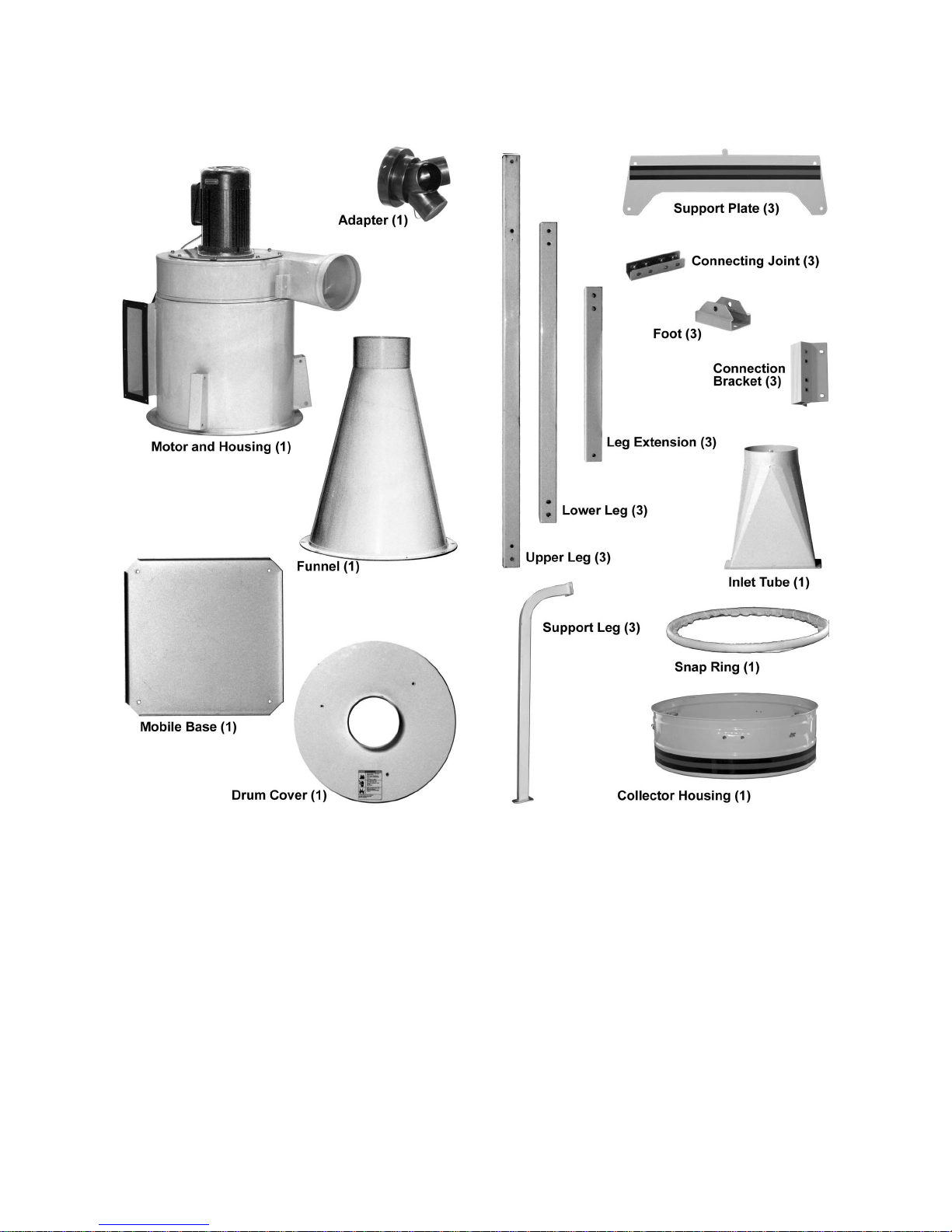
Contents of the Shipping Cartons.............................................................................................................7
Main Unit..............................................................................................................................................7
Canister ...............................................................................................................................................9
Filter Bag .............................................................................................................................................9
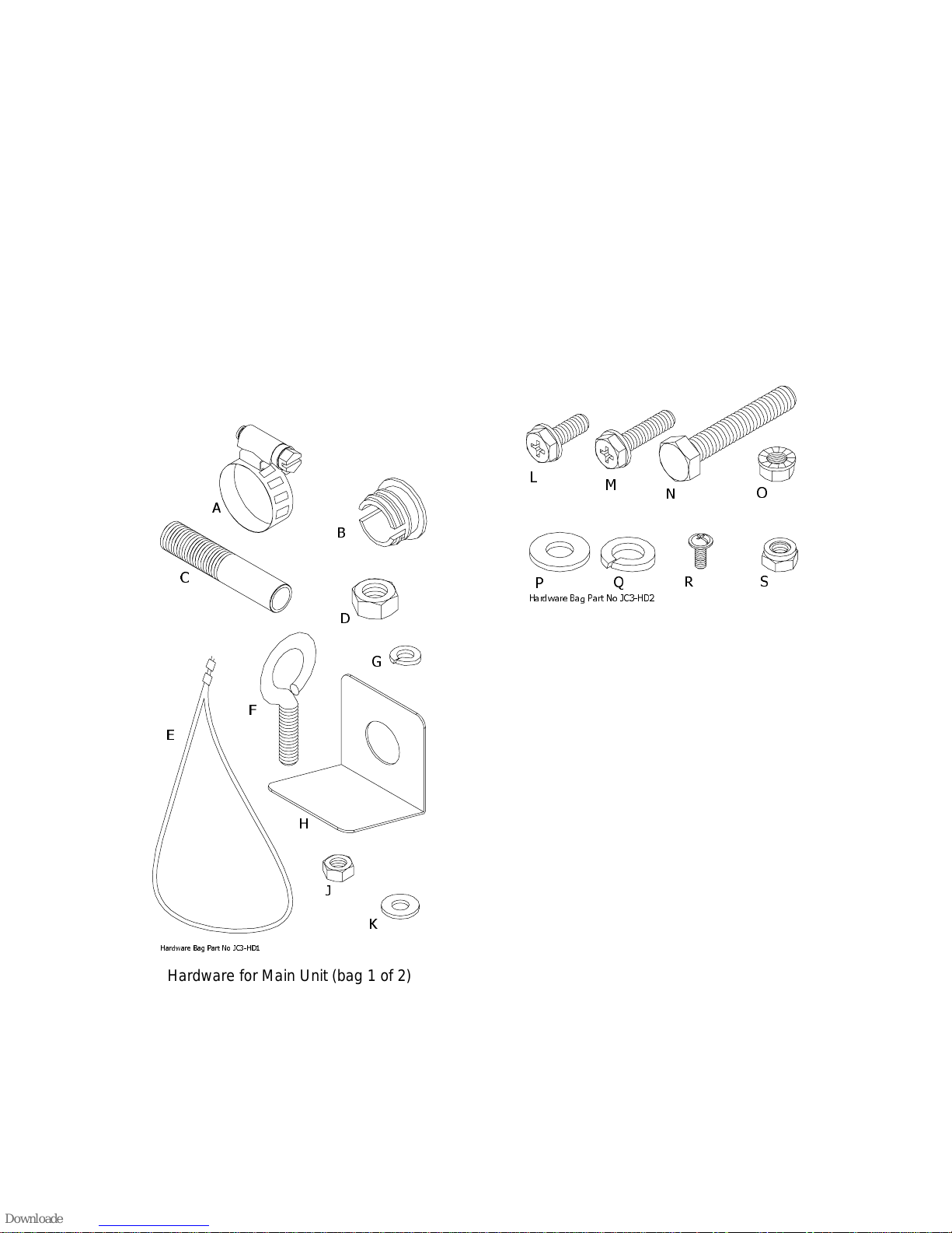
Assembly...............................................................................................................................................10
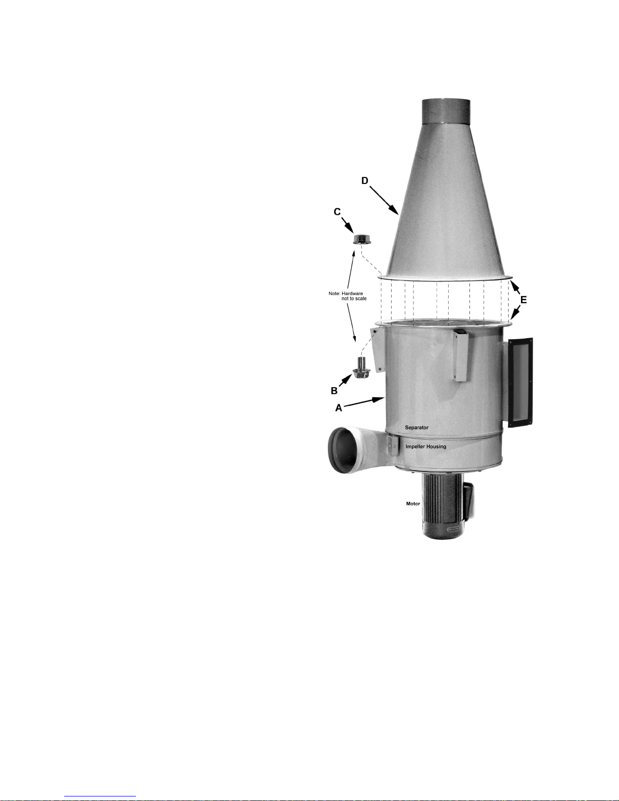
Impeller Housing to Dust Collection Box.............................................................................................10
Leg Assembly ....................................................................................................................................10
Support Frame...................................................................................................................................12
Support Plate.....................................................................................................................................12
Switch, Inlet Tube and Adapter...........................................................................................................12
Base ..................................................................................................................................................13
Collection Drum..................................................................................................................................13
Drum Cover........................................................................................................................................14
Vacuum Hose ....................................................................................................................................14
Collector Housing and Collector Bag..................................................................................................15
Filter Installation.................................................................................................................................15
Canister Filter Installation...................................................................................................................15
Canister Handle Assembly .................................................................................................................16
Filter Bag Assembly ...........................................................................................................................16
Electrical Connections ...........................................................................................................................17
Turning the Machine On & Off................................................................................................................17
Maintenance..........................................................................................................................................17
Cleaning the Filter Bag – Filter Bag Model..........................................................................................17
Removing the Collector Bag – All Models...........................................................................................17
Cleaning the Filter – Canister Model...................................................................................................17
Motor .................................................................................................................................................17
Connecting the Dust Collector to a Machine .......................................................................................18
Grounding the Dust Collection System ...............................................................................................18
Parts......................................................................................................................................................18
Ordering Replacement Parts..............................................................................................................18
Parts List – Main Body Assembly........................................................................................................19
Exploded View – Main Body Assembly...............................................................................................21
Parts List – JC-2CF Canister Filter Assembly .....................................................................................22
Exploded View – JC-2CF Canister Filter Assembly.............................................................................23
Parts List – 5 Micron Filter Bag Assembly...........................................................................................24
Wiring Diagram......................................................................................................................................25
The specifications in this manual are given as general information and are not binding. WMH Tool Group
reserves the right to effect, at any time and without prior notice, changes or alterations to parts, fittings,
and accessory equipment deemed necessary for any reason whatsoever.